ROXX E.SHOW TW+ User manual

User
Manual
E.SHOW TW+
USER MANUAL

2
User
Manual
CONTENT
1. Safety Informations
1.1. General Preventive Measures 4
1.2. Regulations for equipment that connects to power mains 5
1.3.Technical warnsigns and explanation 6
2. Introduction
2.1. About us 7
2.2. E.SHOW TW+ 7
3. General Product Information
3.1. Scope of delivery 8
3.2. Control Functions 8
3.3.Features 8
4. Installation & Setup
4.1 Physical Installation and Rigging 9
4.2 Connections 10
4.2.1. AC Power 11
4.2.2. DMX Connection 11
4.2.2.1. Cable Connection 11
4.2.2.2. Wireless Connection 12
5. Operation
5.1 Start up 15
5.2 Control Display 15
5.3 Display Short Cuts 15
5.4 Conguration 17
5.4.1 Set DMX Start Address (Direct Access) 17
5.4.2 Selecting DMX Mode 17
5.4.3 Stand Alone 18
5.4.4 Slave Mode 25
5.4.5 Settings 25
5.4.6 System Info 29
6. Accessories
6.1. Lenses 30
6.2. More accessories 31

3
User
Manual
7. Technical Data / Diagrams
7.1 Technical drawings and measurements 32
7.2 IP Rating 33
7.3 Technical Data 34
7.4 DMX-Charts / Color Macro Charts / CCT Chart 36
7.5 RDM Templates 52
8. Troubleshooting 53
9. Manufacturer´s Declaration 54

4
1. SAFETY INFORMATION
1.1. General Preventive Measures
1.1.1. Please read, understand and follow the instructions.
1.1.2. Store the instructions and information in a safe place.
Best solution is the ring binder provided by ROXX.
1.1.3. Follow all safety warnings. Under no circumstances remove safety warnings
or other information from the equipment.
1.1.4. Don’t use the equipment for any other intended purpose or manner.
1.1.5. Use only stable and compatible stands and/or brackets. Especially when x installed.
Make sure the wall brackets are properly installed and safe. Make sure the device is securely
installed and cannot fall.
1.1.6. Check the safety regulations applying for your country before and during installation.
1.1.7. Keep the device away from heat! Don’t place/install near heaters, ovens or any source of heat.
Make sure that the device always is efciently cooled and cannot overheat.
1.1.8. Always guarantee that ventilation and cooling slots are clean and not blocked.
1.1.9. Item must be away minimum 20cm from anything around and above it.
1.1.10. Do not use this device close to water.
1.1.11. Do not expose this equipment to ammable materials.
1.1.12. Make sure that no objects can fall into the device.
1.1.13. Only use this device with the accessories recommended by the manufacturer.
1.1.14. Always check the equipment for housing damages, so that no water can enter the device.
No containers containing liquids of any kind should be place on top of the unit.
1.1.15. Opening or modifying this device is only allowed by authorized and qualied persons.
1.1.16. All cables need to be checked after connecting the device in order to prevent damage or accidents.
1.1.17. Make sure that the device is transported safe and packed proper in order to prevent damage of any kind.
1.1.18. Once you notice improper function of your device due to damage, electric shock or anything similar,
immediately unplug the unit from the mains outlet and contact our service department.
1.1.19. Clean the device with a dry cloth.
User
Manual

5
1.1.20. Observe all disposal laws applicable in your country. Especially for the packaging.
1.1.21. Plastic bags are not a toy! Keep away from children!
1.1.22. Please note that changes or modications which are not approved by the party responsible
for compliance will void the user’s authority to operate the device.
1.2 Regulations for equipment that connects to power mains
1.2.1. If an earthing contact is available in the used power cord, it must used in combination
with an power outlet, providing a protective ground. In no circustances should the protective
ground be deactivated.
1.2.2. Do not switch on the device immediately after it has been in strong different temperatures,
especially after transport. Let the device acclimatize to the temparature in the room of usage
rst to prevent moisture and condensation.
1.2.3. Verify that the correct voltage and frequency are available in the area of operation, before
connecting the unit to the mains outlet.
1.2.4. If the plug doesn‘t t in your mains outlet, contact your electrician.
1.2.5. Make sure your power cord/adapter/connector does not show signs of kinks/warps or is being
stepped on.
1.2.6. Allwas disconnect the unit when not in use or being cleaned. Don‘t pull on the cord to disconnect.
Only touch power connections with dry hands!
1.2.7. Don‘t switch the unit on/off rapidly. This may cause damage.
1.2.8. If a fuse needs to be replaced, ALWAYS make sure that exact the same fuse will be used
(type and rating). Repeatedly blown fuses need to be checked by an authorised service technician.
1.2.9. In the risk of lighting strike all units need to be unpluged from the mains in order to prevent damage.
1.2.10. During installation there must be a voltage free condition.
1.2.11. The device needs to be cleaned and serviced regularly and will credit this with a longer life cycle.
Dust, dirt, moist, water, smoke, nicotine or anything similar inside the unit will cause
damage/malfunction.
1.2.12. The unit needs to have at least 0,5m distance to anything ammable.
1.2.13. You have to make sure that any electrical installation applys to the laws of your country.
Correct power cables and applying standards have to be used.
User
Manual

6
1.3. Technical warnsigns and explanation
In order to prevent the risk of an electric shock, under no circumstances remove the cover/back
or open the unit in any way! No user serviceable parts are inside. Service, maintenance and repairs
should only be done by qualied service personnel or the manufacturer.
Dangerous uninsulated voltage inside the device can cause an electrical shock when opened by
unqualied personnel.
Important operating and maintenance instructions apply!
Do not operate this device in tropical climates.
CAUTION! Intense LED light source! Risk of eye damage. Do not look into the light source
The housing surface of the spotlight can heat up to temperatures as high as 70 °C in regular use. Ensure
that it is not possible to come into contact with the housing unintentionally. Always allow sufcient time
for the lamp to cool down before dismantling, carrying out maintenance work or charging etc..
IMPORTANT IMFORMATION!
• This is a product which has been developed for professional usage
in event technology. It is not suitable as a houshold lighting.
• NEVER stare, not even temporarily, directly into the light source.
• Don‘t use magniers or any other optical instrument to look at the beam.
• The effects of this device, expecially the stroboscope effect, can cause
problems for sensitive people or may even cause epileptical seizures.
User
Manual

7
2. INTRODUCTION
2.1. About us
The name ROXX®came easily.
Combined with the concentrated knowledge and many years of experience, our three founders, who have been
leaving their mark in the event and lighting industry for many years already, came together in 2020 to start this
outstanding venture.
Product development, sales and marketing as well as the exceptional know-how and the profound rooting in the
eld of the professional lighting technology belong to our core competences and therefore guarantee extremely in-
novative and reliable products, excellent support and professional service in every aspect.
Designed & developed in Germany
ROXX®products are developed and designed in Germany. Always in tight consultation with our customers and
experts who will eventually be working with these tools. This ensures innovative, easy-to-use and performance-
oriented solutions, which provide added value for our customers.
Made to last
Recommended for permanent outdoor use, most ROXX®products feature additional corrosion protection and en-
hanced IP66 equipment protection, thereby providing that crucial extra for a wider range of applications. In addition
to architectural or theme park applications, even xed installations in coastal or offshore areas with high salt expo-
sure can be reliably implemented over long periods of time.
2.2. E.SHOW TW+
ROXX® Entertainment SHOW Series offers very high performance, weatherproofxtures and features Single-
Source-LEDs that produce an incredibly smooth lighting and uniform colors, providing a solution for any requirement.
The LED variations range from a Tunable White over to a Full Color to a pure Tungsten and up to a Daylight version.
Each one reaching an exceptionally good light quality with high CRI / TLCI and a massive light luminosity.
The E.SHOW TW+ (Tunable White Plus) convinces in every sort of application with excellent white tones and a
wide color range due to its 6 color LED engine. The addition of Amber, Lime and Cyan extends the color spectrum
by 15%, which immensely increases the light quality and color variety of the xture. To ensure consistent colors
throughout all xtures and excellent whites as dened by the black body curve, ROXX®Color Calibration performs
color matching across the entire range. Thanks to the specially developed ROXX®R.LOK®technology, the lenses can
be changed easily and without any tools. This allows the beam angle to be conveniently adjusted, whether from 19°,
36°, 59° or elliptical 17°x24° and 19°x57°.
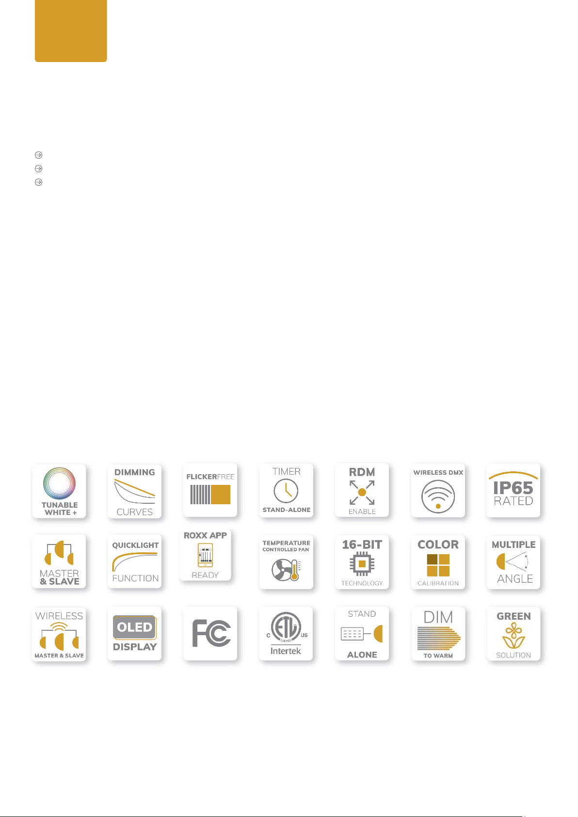
In addition to DMX and RDM control, Lumenradio‘s latest Wireless DMX technology (CRMX) enables wireless as
well as exible control plus integrating a Bluetooth interface allows direct controlling via unique ROXX.APP without
additional hardware. Covering all possible requirements, the xture includes an extensive range of accessories
including 8-Way Barndoor, Honey Comb, Anti-Glare Shield, various lenses, Gel Frame, Omega Bracket and a spe-
cially developed Snapbag®and Snapgrid®by DoPchoice for an extremely even illumination of motifs in front of the
camera.
User
Manual

8
3. GENERAL PRODUCT INFORMATION
3.1. Scope of delivery
1x E.Show TW+
Power cord with plug (EU country specic, if not ordered differently)
Pendant luminaire closing caps
We´re offering a wide range of professional accessories (optional). Please see under menu 6 or at our website
www.roxxlight.com
3.2. Control Functions
• 3CH CCT, 3/6/9/11/14CH RGB, 6/12/13/20CH DIRECT, 3/10CH HSI
• Stand Alone Functions including cinema effects, various auto programs, customisable scenes, CCT,
LEE adjusted color macros and custom color templates (RGBALC)
• Master & Slave (by DMX and Wireless DMX)
• Wireless DMX (Lumenradio CRMX®)
• ROXX App - Bluetooth 5.0
3.3. Features
User
Manual

9
4. INSTALLATION & SETUP
4.1 Physical Installation and Rigging
ROXX E.SHOW TW+ may be installed in any orientation. For this purpose the product provides several options:
Standing:
The xtures yoke with its implemented rubber feet is designed to ensure a secure stand on nearly every plane surfa-
ce with every possible angle/orientation of the lamp´s head. Please take care that supporting surfaces are loadable
and stable.
Hanging:
On the bottom the yoke provides 2 Camlock QuickRelease connectors. Here it´s possible to click in the ROXX Omega
Bracket ST (optional accessory) equiped with any suitable clamp.
Insert the two fasteners and turn each 90° clockwise to lock them. Please be sure that the fasterners are turned fully
and snaped in.
A centric hole on the yoke´s bottom (d=13mm / 0,51 inch) provides a mounting point for more rigging options like
a (Mini-) TV Spigot, to use the E.Show on a tripod or for example with a superclamp.
User
Manual
Omega Bracket ST
Closed
Open

10
Pendant Light*:
The sophisticated and attractive design of the ROXX E.SHOW TW+ makes the luminaire predestinated for the use
as a pendant light, e.g. for exhibition booths, galas,… The position of the safety eyelet and the lamp body balancing
makes that possible in a perfect way. Dismount the Yoke by turning out the both wing screws completely and detach
them together with the Yoke and the scaled plastic parts. Seal the apertures with the 2pcs covering "Pendant Caps"
(inlcuded). Use the safety eyelet for hanging down the E.Show.
Note:
To hang down the xture as a pendant light with only one wire and without the need of a secondary safety
the setup has to be done as a „stationary installation“. Please mounting material, that is not dismountable
without tools (e.g. halfcoupler with nut and chain link).
Also in this application, please take care of the current requirements and regulations for dimensioning and design of
the used wires, clamps and all other possible mounting materials.
Always take care of an adequate distance between the xture and surrounding surfaces and be sure to keep the
fans outlets free for good ventilation.
4.2 Connections*
A: Mains In: IP65 Power input connector with rubber sealing cap.
Connect using the provided power cable
(when not in use, always
close with rubber sealing cap).
B: Mains Out:
IP65 Power output connector with rubber
sealing cap.
Provides power to additional xtures. Ensure that the total power
consumption of all daisy-chained devices connected do not ex-
ceed 8A (Ampere)! (when not in use, always close with rubber sea-
ling cap).
C: DMX IN: Male IP65 5-pin XLR connector (when not in use, al-
ways close with rubber sealing cap).
D: DMX OUT:
Female IP65 5-pin XLR connector
when not in use, always close with rubber sealing cap
).
E: GoreTex
F: Safety Eyelet
*Note:
In order to provide protection from spraying water, in accordance with protection class IP65, special IP65-
rated XLR connectors must be used correctly with the DMX input and output sockets, or they must be closed
using the rubber sealing caps. When connected correctly, or when sealed correctly with the rubber sealing
caps, the POWER IN and POWER OUT sockets are protected from spraying water, as in accordance with IP65.
User
Manual
A
B
D
C
F
E

11
4.2.1. AC Power
The E.SHOW TW+ operates on any 100–260 V, 50/60 Hz AC mains power supply with a maximum power con-
sumption of 220W.
Connect the xture to AC power using the supplied cable or a similar one with Neutrik powerCON TRUE1 NAC3FX-W
or a compatible type, to ensure the correct ingress protection (IP).
For temporary installations, the mains cable must be tted with a grounded connector intended for exterior use. The
xture must be grounded/earthed and be able to be isolated from AC power. The AC power supply must incorporate
a fuse or circuit breaker for fault protection.
Warning!
Read “Safety Informations” starting on page 3 before connecting the xtures to AC mains power!
Do not connect the xture to an electrical dimmer system, as doing so may cause damage that is not
covered by the product warranty!
4.2.2. DMX Connection
The
E.SHOW TW+
is fully controllable by DMX (USITT DMX512-A standard, based on RS-485) and RDM. It can be
connected using either DMX cables or via the built-in LumenRadio CRMX wireless system.
4.2.2.1. Cable Connection
If using a cabled DMX system, connect the DMX IN cable to the input connector (male 5-pin XLR connector) and
DMX OUT cable to the output (female 5-pin XLR connectors).
For outdoor installations, use only IP65-rated XLR connectors.
Use shielded twisted pair cable designed for RS-485 devices. The cables are daisy chained between the xtures,
and up to 32 xtures can be connected to the same DMX link. Up to 300 meters (1000ft.) of cable is achievable with
high quality DMX cables. All DMX links must be terminated in the last xture by connecting a DMX termination plug
to the last xture’s 5 pin DMX out connector.
Standard microphone cable is not suitable for transmitting DMX.
User
Manual
Wire Color (EU models) Wire Color (US models) Conductor Symbol
Brown Black Live L
Blue White Neutral N
Yellow / Green Green Ground (earth) or
1DATA
GND
DMX Termination
on last xture DMX out
DATA -
DATA +
120 Ohm
+/- 5%
5
2 4
3
1DATA
GND
XLR pin out
DATA -
DATA +
5
2 4
3

12
4.2.2.2. Wireless Connection*
E.SHOW TW+ is equipped with a LumenRadio ™ Transceiver module.
This enables the xture to work with the following connectivity options:
Working in Receiver Mode: receive wireless DMX- and RDM Signals via CRMX
Working in Transmitter Mode: transmit DMX (1 universe) to other units via CRMX
Full Control via Bluetooth 5.0 and ROXX App
The Fixture is able to send DMX-data received by CRMX or Bluetooth to its physical DMX-Output XLR Connector
and hereafter, plugged in by cable, to any DMX-capable unit. For this please enable "Pass to DMX Out" inside Wi-
reless DMX Settings.
E.SHOW TW+ can act as a fully operative CRMX Receiver and be paired to an active wireless transmitter (CRMX)
simultanously as being connected to a cabled DMX. The device will prioritize cabled DMX input over wireless DMX
and over Bluetooth. A small indicator infront of "DMX", "CRMX" or "BLE" gives an easy overview which protocol is
curently active. Please see the display graphics below.
If using a wireless DMX system, ensure that the DMX input and the DMX output are properly sealed. Connect both
DMX IN and DMX OUT, or seal, in order to maintain the xture’s IP65 rating.
*Note: If you are using XLR for DMX and not Bluetooth we recommend to not connect to Bluetooth unless
you need to since it can cause a few dropped DMX packets.
BLE and CRMX RX are not available simoultaneously.
• If CRMX RX is enabled and BLE will enabled after, CRMX automatically changes to TX mode.
• If CRMX TX operating mode is changed to RX, BLE will be disabled automatically.
User
Manual
9 CH
RGB Next
( 10 )
•DMX
1
CRMX Disabled
The indicator infront of "DMX"
shows that DMX is active.
Operation Mode n.a.
Linked No
Receive Reset No
DMX Enabled
BLE (Bluetooth) Disabled
9 CH
RGB Next
( 10 )
DMX
• CRMX(RX)
1
CRMX Enabled
The indicator infront of "CRMX
(RX)" shows that the xture is
now working in wireless DMX
receive mode.
"(RX)"= CRMX operating mode
is set to receive
Operation Mode RX
Linked No
Receive Reset Yes
DMX Disconnect
BLE (Bluetooth) Disabled

13
User
Manual
9 CH
RGB Next
( 10 )
DMX
• CRMX(TX)
1
CRMX Enabled Once the xture is linked to an
external transmitter, the CRMX
signal-symbole appears on
upper left side.
1 dash= 1-30% signal strength
2 dashs= 31-70% signal strength
3 dashs= 71-100% signal strength
Operation Mode TX
Linked Yes
Receive Reset Yes
DMX Disconnect
BLE (Bluetooth) Disabled
9 CH
RGB Next
( 10 )
DMX
• CRMX(RX)
1
CRMX Enabled
In case the external trans-
mitter is switched off or out of
signal range the signal-sym-
bole starts to blink.
Operation Mode RX
Linked Yes
, out of range
Receive Reset Yes
DMX Disconnect
BLE (Bluetooth) Disabled
CRMX Enabled
An exclamation appears and
blinks although the external
transmitter is switched on and
is inside the signal range but
no DMX is connected to the
external transmitter.
Operation Mode RX
Linked Yes, but no DMX
Receive Reset Yes
DMX Disconnect
BLE (Bluetooth) Disabled
9 CH
RGB Next
( 10 )
DMX
• CRMX(RX)
1
!
9 CH
RGB Next
( 10 )
DMX
• CRMX(TX)
1
CRMX Enabled
The indicator infront of "CRMX
(TX)" shows that the xture is
now working in wireless DMX
transmit mode.
"(TX)"= CRMX operating mode
is set to transmit
Operation Mode TX
Linked No
Receive Reset Yes
DMX Disconnect
BLE (Bluetooth) Disabled
9 CH
RGB Next
( 10 )
DMX
• CRMX(RX)
1
CRMX Enabled Once the xture is linked to an
external transmitter, the CRMX
signal-symbole appears on
upper left side.
1 dash= 1-30% signal strength
2 dashs= 31-70% signal strength
3 dashs= 71-100% signal strength
Operation Mode RX
Linked Yes
Receive Reset Yes
DMX Disconnect
BLE (Bluetooth) Disabled
4.2.2.2. Wireless Connection

14
User
Manual
9 CH
RGB Next
( 10 )
DMX
• BLE
1
CRMX Disabled
The indicator infront of "BLE"
shows that the xture is now
working in Bluetooth mode and
is paired to ROXX App.
Operation Mode n.a.
Linked No
Receive Reset No
DMX Disconnect
BLE (Bluetooth) Enabled + Paired
CRMX Enabled The indicator infront of "BLE"
shows that the xture is now
working in Bluetooth mode and
is paired to ROXX App.
As CRMX TX is enabeld and
linked a full DMX universe is
send out by CRMX (wireless
DMX).
Operation Mode TX
Linked Yes
Receive Reset No
DMX Disconnect
BLE (Bluetooth) Enabled + Paired
9 CH
RGB Next
( 10 )
DMX
• BLE
1
CRMX(TX)
CRMX Enabled
DMX is active.
As CRMX TX is enabled and
linked a full DMX universe is
send out by CRMX (wireless
DMX).
Operation Mode TX
Linked Yes
Receive Reset No
DMX Connect
BLE (Bluetooth) Enabled
9 CH
RGB Next
( 10 )
• DMX
BLE
1
CRMX(TX)
CRMX Enabled
No indicator infront of "BLE",
xture is not paired to ROXX
App.
Operation Mode TX
Linked Yes
Receive Reset No
DMX Disconnect
BLE (Bluetooth)
Enabled, not paired
9 CH
RGB Next
( 10 )
DMX
BLE
1
CRMX(TX)
4.2.2.2. Wireless Connection

15
5. OPERATION
5.1 Start up*
Once the xture is connected to AC power, the boot process starts and the following information will appear on the
display:
“Ready to ROXX”, the product name and the current software version.
After this process, the xture is ready for operation, and starts in the previous-
ly enabled mode.
*Note:
During boot process the fan spins up quickly to blow out some possible
dust from last use.
5.2 Control Display*
OLED Display with Touch-Sensitive controls
Press ENTER to access the selection menu for system settings or conrm changes.
Press ESC to take a step back in the menu.
Press arrows to scroll up and down inside the menu and change values, such as DMX address.
*Note:
For a smooth navigation thru the menu settings, please make sure the display surface is dry and dust free.
After approximately 1 minute of inactivity inside the menu settings, the display will automatically jump back
to home screen.
5.3 Display Short Cuts*
Short Cuts
For some always recurring functions the xture allows quick and user-friendly access at home screen over some dis-
play control short-cuts:
User Reset or Factory Reset*
Pressing ESC+ENTER simultaneously a Factory Reset or User Reset can be started.
By using the up/down arrows the Factory- or User Reset can be selected.
For conrming press ENTER, to jump back please press ESC.
*Note:
After Factory Reset all xture settings are set back to factory default values.
After User Reset all user selected reset functions and user default values will set back.
Also a short self-test will start immediately while dimming in and out each single color.
User
Manual
ESC
ENTER ESC
+
ENTER

16
Display Off
Pressing ESC + arrow down simultaneously the display backlight function will set to off and the display will turn off
immediately. Once a control is pressed the display backlight will turn on.
BLE enabled / disabled
Pressing ESC + Arrow Up simultaneously the Bluetooth will enabled or disabled.
Conrm by pressing ENTER, step back by pressing ESC.
Manual display ip function*
The xture includes an auto display ip function by default.
To use the manual display ip function please disable the auto ip function under Settings / Display rst. Once the
auto display ip function is disabled you can use the manual display ip function by pressing arrow up + arrow down
simultaneously. The display will rotate 180. By pressing both arrows simultaneously again the display will ip back.
*Note:
Once the display is ipped both Up / Down controls will work according to the display rotation.
Quick Light function
(hold 3 seconds)
For easy and fast operation during setting the lights the xture includes a user-friendly Quick Light function (Daylight
5600 Kelvin). If DMX, CRMX or Bluetooth is not assigned please press and hold ENTER for 3 seconds at homescreen,
after the Quick Light function will appear.
Here dimmer can be adjusted from 0-100% by using up/down arrows, to take over the dimming value please press
ENTER to conrm.
User
Manual
ESC
ESC
ENTER
+
+
+

17
5.4 Conguration
Home Screen
After boot process the xture is ready for operation and starts in the previously enabled mode. At home screen the
following information will appear, depending on the current operating mode:
A
DMX Adress
B
Operating Mode (DMX Mode, Quick Light or Standalone Mode)
C
Next available DMX address depending on the xtures DMX footprint
D
External Data protocol (CRMX, DMX, BLE).
E
CRMX status and strength
F
The dot indicates the active protocol
Note:
CRMX (RX)
C
RMX Receiving Mode
CRMX (TX)
C
RMX Transmit Mode
BLE
Bluetooth enabled
5.4.1 Set DMX Start Address (Direct Access)
At Home Screen the DMX address can be changed directly by using the up and down arrows. During this process the
DMX address starts blinking, once it´s conrmed by pressing ENTER it stops blinking.
If the DMX address will not be conrmed by ENTER within 10 seconds, the display will jump back and show the DMX
address from before and stops blinking.
5.4.2 Selecting DMX Mode*
At home screen please press ENTER to access to the main menu (level 1).
While using UP / DOWN arrows, please select the menu item “DMX Mode” and conrm
by pressing ENTER.
In the following sub-menu (level 2), you can now choose between 12 different DMX operating modes while using the
UP/Down arrows and conrm by pressing ENTER or jump back by pressing ESC.
After conrmation the display will jump back to main menu (level 1). Press ESC for homescreen, here the selected
DMX mode will be displayed.
*Note:
For detailed information about the several DMX modes including channel assignment please see our DMX
Control chart.
.
User
Manual
9 CH
RGB Next
( 10 )
•DMX
BLE
CRMX(TX)
1
B
A
C
D
F
E

18
5.4.3 Stand Alone*
Press ENTER to access to main menu (level 1).
While using the UP / DOWN arrows, please select the menu item “Stand Alone” and conrm
by pressing ENTER.
In the following sub-menu (level 2), you can now choose between 6 different Stand Alone operating modes (Auto,
Editor, Color Macro, Quick Color, Tunable White, User Color) ,Stop Stand Alone, Timer and Color Settings functions
while using the UP/Down arrows and conrm by pressing ENTER or jump back by pressing ESC.
To nally use Stand Alone programs please make sure either DMX, CRMX RX or BLE is connected to the xture, as
these protocols have priority.
Stop Stand Alone
To stop a running Stand Alone mode immediately, please select “Stop Stand Alone” and conrm by pressing ENTER.
The display will automatically jump back to level 1.
Auto*
Select “Auto” by using the up/down arrows and press ENTER.
Here at sub-menu (level 3), you can choose between 10 different Auto Programs
(7-Color Fade, 7-Color Jump, 15-Color Fade, 15-Color Jump, Police
RB, Police B, Candle Light, Fireworks, Red Carpet
and Welding) and Stop Program.
Using the Up/Down arrows you can select one of the 10 auto programs and conrm
by pressing ENTER or step back by ESC.
User
Manual
Menu
Level 1
DMX Mode
Stand Alone
Slave
Settings
System Info
DMX Mode
Level 2
3CH CCT – Factory Calibrated
3CH RGB – Factory Calibrated
6CH RGB – Factory Calibrated
9CH RGB (Default) – Factory Calibrated
11CH RGB – Factory Calibrated
14CH RGB – Factory Calibrated
6CH DIRECT - RAW
12CH DIRECT - RAW
13CH DIRECT - RAW
20CH DIRECT – RAW
3CH HSI – Factory Calibrated
10CH HSI – Factory Calibrated
Menu
Level 1
DMX Mode
Stand Alone
Slave
Settings
System Info
Stand Alone Mode
Level 2
Stop Stand Alone
Auto
Editor
Color Macro
Quick Color
Tunable White
User Color
Timer
Color Settings

19
After conrming your preferred Auto Program, you can now adjust speed and brightness at level 4.
To adjust speed, please use the UP / DOWN arrows to select the menu item “Speed”, and conrm with ENTER. After
use UP / DOWN arrows to adjust the speed value between 000-100 and conrm by ENTER or jump back by ESC.
To adjust brightness please select “Dim” as per the procedure previously described and conrm with ENTER. After
use UP / DOWN arrows again to adjust the brightness value between 000-100 and conrm by ENTER or jump back
by ESC.
Once it´s conrmed or denied the display will automatically jump back to level 3.
To stop running a selected auto program please chose “Stop Program” at level 3 or "Stop Stand Alone" at level 2.
For returning back to homescreen please press ESC three times.
At homescreen the selected Stand Alone mode “Auto” and the selected program will be displayed.
*Note:
Using arrows UP /DOWN at homescreen Auto programs can be directly changed according to the list.
Editor*
At Editor you have up to three customizable programs which can be dened and run from the menus.
Each of the three values contains twenty four user-denable scenes with its own values for RGBALC (RAW) or RGB
(Calibrated) and shutter, playing continuously in a loop.Each scene has a denable fade-in time for the transition from
one color to the other and wait-time.
To dene a program please press ENTER to access to main menu (level 1).
While using the UP / DOWN arrows, please select the menu item “Stand Alone” and conrm
by pressing ENTER.
User
Manual
Menu
Level 1
DMX Mode
Stand Alone
Slave
Settings
System Info
Stand Alone Mode
Level 2
Stop Stand Alone
Auto
Editor
Color Macro
Quick Color
Tunable White
User Color
Timer
Color Settings
Auto
Level 3
Stop Program
7-Color Fade
7-Color Jump
15-Color Fade
15-Color Jump…..
Police RB
Police B
Candle Light
Fireworks
Red Carpet
Welding
Program
Level 4
Speed <0-100>
(Default 50)
Dim <0-100>
7-Color Fade
Auto

20
Select “Editor” by using the up/down arrows and press ENTER.
Here at sub-menu (level 3) you can choose between Program 1-3, Dimmer and Stop Program.
Using the Up/Down arrows you can select program 1, 2 or 3 and conrm by pressing ENTER or step back by ESC.
After conrming your preferred program, you can now choose between Scene 1-24.
Select one of the scenes and press ENTER or step back by ESC.
At level 5 you can now set your color, shutter and fade / wait time in minutes and seconds. For creating a color jump
please set value for "Fade Time" to 0, and "Wait Time" to at least 1 second.
Once it´s set your rst scene is programmed.
You can now jump back to level 3 by using ESC. Here your program will starts automatically.
For creating more scenes please use the same procedure.
To stop an active program please press ESC and select “Stop Program” at level 3 or "Stop Stand Alone" at level 2.
To start again, please re-select your preferred program, it will starts automatically again.
To adjust the master brightness for program 1-3, you can use the item “Dimmer” at level 3 and select between 000-
100 and conrm by ENTER or jump back by ESC.
*Note: Once "Factory Calibration" is selected under "Color Settings" inside Stand Alone, only values for
RGB are available here.
Using UP / DOWN arrows at homescreen Editor program can be
directly
changed according to the list.
For choosing the right strobe effect please follow the Strobe Channel from our DMX chart at the end of this
manual.
User
Manual
Menu
Level 1
DMX Mode
Stand Alone
Slave
Settings
System Info
Stand Alone Mode
Level 2
Stop Stand Alone
Auto
Editor
Color Macro
Quick Color
Tunable White
User Color
Timer
Color Settings
Editor
Level 3
Program 1
Program 2
Program 3
Dim <0-100>
Stop Program
Program
Level 4
Scene 1
Scene 2
Scene 3
…max. 24 Scenes
Scene
Level 5
Red <0-255>
Green <0-255>
Blue <0-255>
Amber <0-255>
Lime <0-255>
Cyan <0-255>
Shutter <0-255>
Fade Time (min.) <0-480>
Fade Time (sec.) <0-59>
Wait Time (min.) <0-720>
Wait Time (min.) <0-59>
Table of contents
Other ROXX Dj Equipment manuals
Popular Dj Equipment manuals by other brands

Wecan Technology and Lighting Co., Ltd
Wecan Technology and Lighting Co., Ltd WKY-BEAM12 Use manual

AVE
AVE HEX-FLAT6 user manual

Zzipp
Zzipp ZZJET3500 user manual

Chauvet Professional
Chauvet Professional Maverick Force 1 Spot user manual

Roland
Roland CPM-120 Operation manual

leahua
leahua LH-D030 user manual