manuals.online logo
Brands
  1. Home
  2. •
  3. Brands
  4. •
  5. Royal Vendors
  6. •
  7. Accessories
  8. •
  9. Royal Vendors GIII User manual

Royal Vendors GIII User manual

SUBJECT: GIII Controller Chute Sensor Adjustment
MODELS: All GIII / GIII Plus models
TOOLS REQUIRED: Flat screwdriver
ESTIMATED TIME: <2 minutes
ANY QUESTIONS? CONTACT ROYAL VENDORS’ CUSTOMER SERVICE DEPARTMENT
IN NORTH AMERICA, CALL TOLL FREE 1 800 931 9214
F0019077.FRM REV.: A
ISSUE DATE: 23 MAR 2000 REV. DATE: 23 MAR 2000
078
INFORMATION: This document describes the correct procedure
for adjusting the sensitivity of the chute sensor on venders with GIII controllers.
R
Page: 1 of 2
Date: 22 Dec 2015
Revision: 00
Number of
People
Required
R
426 Industrial Boulevard • Kearneysville WV 25430-2776 • USA
Telephone: +1 304 728 7056 • [email protected]
Toll-free in North America: 1 800 931 9214 • Fax: +1 304 725 4016
Canada: +1 905 738 5777 • Mexico: +52 55 5203 6887
Europe: +49 2158 95 1000 • Australia: +61 2 9890 5433
The following areas of this vender contain voltage which can
cause serious injury or even death: the main power cord,
supplying 115-230 VAC to the evaporator, EMI filter,
refrigeration system, monitor, and computer; the power line
from the EMI filter to the ballast and transformer; and the
ballast, which can produce upwards of 600 volts. Remove all
power from the vender before working in any of these areas.
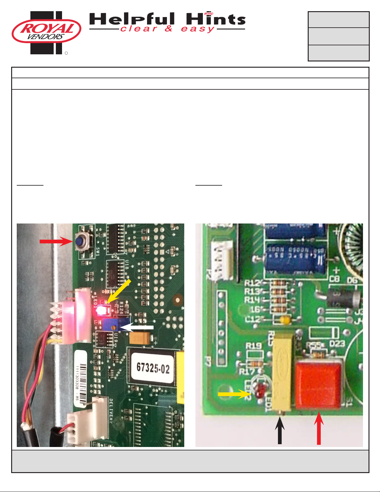
KO Controller (blue mode button):
Located near the control board’s chute sensor connector at position R126 is the sensor adjustment trimpot, which includes an
adjustment screw. (See Figure 1, on page 2.) The trimpot is used to adjust and fine tune the sensor. Located adjacent to the trimpot is
the sensor adjustment LED indicator light, at position LED1. The indicator light is mainly used to aid in adjusting the sensor, but can also
be used to test its operation during product impact.
FACTORY SETTING
Piezo sensor (at, newer-style sensor)
1. Turn the adjustment screw clockwise until the indicator light comes on.
2. Turn the screw counterclockwise until the light just goes out completely.
3. Continue to turn the screw counterclockwise 3/4 of a turn (one full turn is 360°).
4. Test vend columns 7 and 12 for proper function.
Impact sensor (hat-shaped, older-style sensor)
1. Turn the adjustment screw clockwise until the indicator light comes on.
2. Turn the screw counterclockwise until the light just goes out completely.
3. Continue to turn the screw counterclockwise 1 1/2 turns (one full turn is 360°).
4. Test vend columns 7 and 12 for proper function.
GII VII / EVS Controller (red mode button):
Located next to the control board’s mode button at position R15 is the sensor adjustment trimpot, which includes an adjustment
screw. (See Figure 2, on page 2.) The trimpot is used to adjust and fine tune the sensor. Located adjacent to the trimpot is the sensor
adjustment LED indicator light, at position LED1. The indicator light is mainly used to aid in adjusting the sensor, but can also be used to
test its operation during product impact.
FACTORY SETTING
Piezo sensor (at, newer-style sensor)
1. Turn the adjustment screw clockwise until the indicator light comes on.
2. Turn the screw counterclockwise until the light just goes out completely.
3. Continue to turn the screw counterclockwise 3/4 of a turn (one full turn is 360°).
4. Test vend columns 7 and 12 for proper function.
Impact sensor (hat-shaped, older-style sensor)
1. Turn the adjustment screw clockwise until the indicator light comes on.
2. Turn the screw counterclockwise until the light just goes out completely.
3. Continue to turn the screw counterclockwise 2 turns (one full turn is 360°).
4. Test vend columns 7 and 12 for proper function.
ANY QUESTIONS? CONTACT ROYAL VENDORS’ CUSTOMER SERVICE DEPARTMENT
IN NORTH AMERICA, CALL TOLL FREE 1 800 931 9214
F0019077.FRM REV.: A
ISSUE DATE: 23 MAR 2000 REV. DATE: 23 MAR 2000
R
SUBJECT: GIII Controller Chute Sensor Adjustment
MODELS: All GIII / GIII Plus models
Page: 2 of 2
Date: 22 Dec 2015
Revision: 00
R
426 Industrial Boulevard • Kearneysville WV 25430-2776 • USA
Telephone: +1 304 728 7056 • technicalinquiry@royalvendors.com
Toll-free in North America: 1 800 931 9214 • Fax: +1 304 725 4016
Canada: +1 905 738 5777 • Mexico: +52 55 5203 6887
Europe: +49 2158 95 1000 • Australia: +61 2 9890 5433
078
Adjustments after factory setting:
For multiple vending, make sure the sensor is adjusted to the factory specifications as listed above. Next, turn the adjustment screw
clockwise 1/8 turn (piezo sensor) or 1/4 turn (impact sensor) to increase sensitivity. Test vend columns 7 and 12, and watch the light on
the board for a good on and off flash. If still multiple vending, turn the adjustment screw an additional 1/8 turn (piezo sensor) or 1/4
turn (impact sensor) clockwise until proper adjustment is made.
For dry vending (cancelled credit with no product delivery) from all columns, make sure the sensor is adjusted to the factory
specifications as listed above. Next, turn the adjustment screw counterclockwise 1/8 turn (piezo sensor) or 1/4 turn (impact sensor) to
decrease sensitivity. Test vend columns 7 and 12. If still dry vending, turn the adjustment screw an additional 1/8 turn (piezo sensor) or
1/4 turn (impact sensor) counterclockwise until proper adjustment is made.
Figure 1. KO controller
The white arrow points to the trimpot (posion R126) and
adjustment screw. The yellow arrow points to the indicator light
(posion LED1, lit in this photograph for visibility). The red arrow
points to the service mode buon at posion SW1.
Figure 2. GII VII / EVS controllers
The black arrow points to the trimpot (posion R15) and
adjustment screw. The yellow arrow points to the indicator light
(posion LED1). The red arrow points to the service mode buon
at posion S1.

This manual suits for next models

1

Popular Accessories manuals by other brands

Quincy lab 140AE-1 operating manual

Quincy lab

Quincy lab 140AE-1 operating manual

HomePro ZIR000 user manual

HomePro

HomePro ZIR000 user manual

DOL 20SCR Technical user guide

DOL

DOL 20SCR Technical user guide

RAB Smart Task installation manual

RAB

RAB Smart Task installation manual

Kemppi KMS 300 quick guide

Kemppi

Kemppi KMS 300 quick guide

Stearns 57,500 Series Installation and service instructions

Stearns

Stearns 57,500 Series Installation and service instructions

iGuzzini TWILIGHT COPENAGHEN manual

iGuzzini

iGuzzini TWILIGHT COPENAGHEN manual

Adelaide Annexe & Canvas Avan Deluxe installation guide

Adelaide Annexe & Canvas

Adelaide Annexe & Canvas Avan Deluxe installation guide

OHAUS 5000 instruction manual

OHAUS

OHAUS 5000 instruction manual

HOME8 WLS1300 quick start guide

HOME8

HOME8 WLS1300 quick start guide

MAXBOTIX MaxSonar quick start guide

MAXBOTIX

MAXBOTIX MaxSonar quick start guide

ioSmart iSmart56 Installation and user guide

ioSmart

ioSmart iSmart56 Installation and user guide

Focusrite Scarlett 18i8 user guide

Focusrite

Focusrite Scarlett 18i8 user guide

Velleman ED38105 user manual

Velleman

Velleman ED38105 user manual

JumpSport SkyBounce user manual

JumpSport

JumpSport SkyBounce user manual

Prima-Temp PRIYA Instructions for use

Prima-Temp

Prima-Temp PRIYA Instructions for use

Tefcold BC85I-BC85I W user manual

Tefcold

Tefcold BC85I-BC85I W user manual

Vaisala WMS302 user guide

Vaisala

Vaisala WMS302 user guide

manuals.online logo
manuals.online logoBrands
  • About & Mission
  • Contact us
  • Privacy Policy
  • Terms and Conditions

Copyright 2025 Manuals.Online. All Rights Reserved.