RPS Tankless Pressure Pump TP750 User manual

RPSwaterpumps.com
Tankless Pressure Pump™
& Eco-Steady Booster Pump™
User Manual
Systems including TP750, BP1, BP2, BP3

RPSwaterpumps.com

RPSwaterpumps.com

RPSwaterpumps.com
INSTALLATION DETAILS
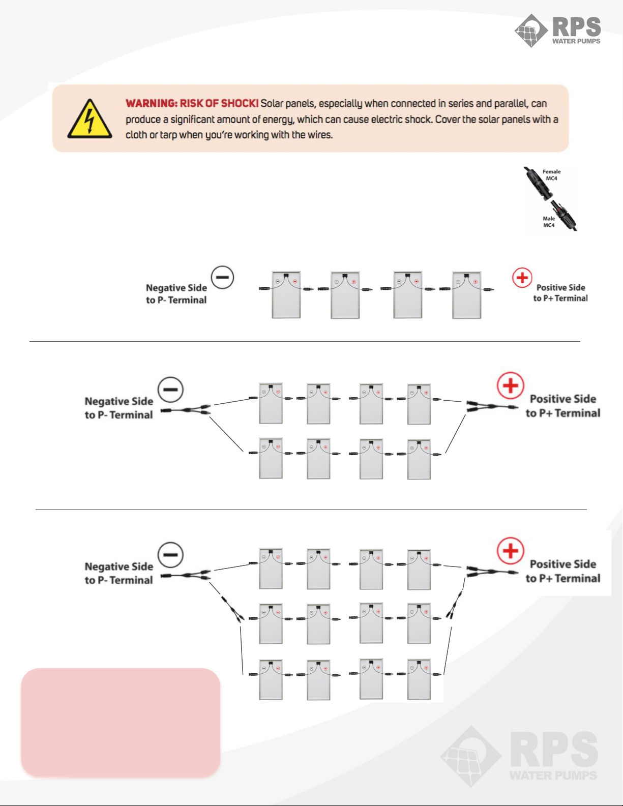
Ensure there are no shadows or other obstructions on the solar panels. While shadowing a small
corner of a single panel may not seem like a big deal, since the panels are connected in series, a small
shadow can limit the power output from all other panels connected in series! This means a small
shadow on a single panel could reduce system power by hundreds of watts. Time to get out that
chainsaw and trim some trees!
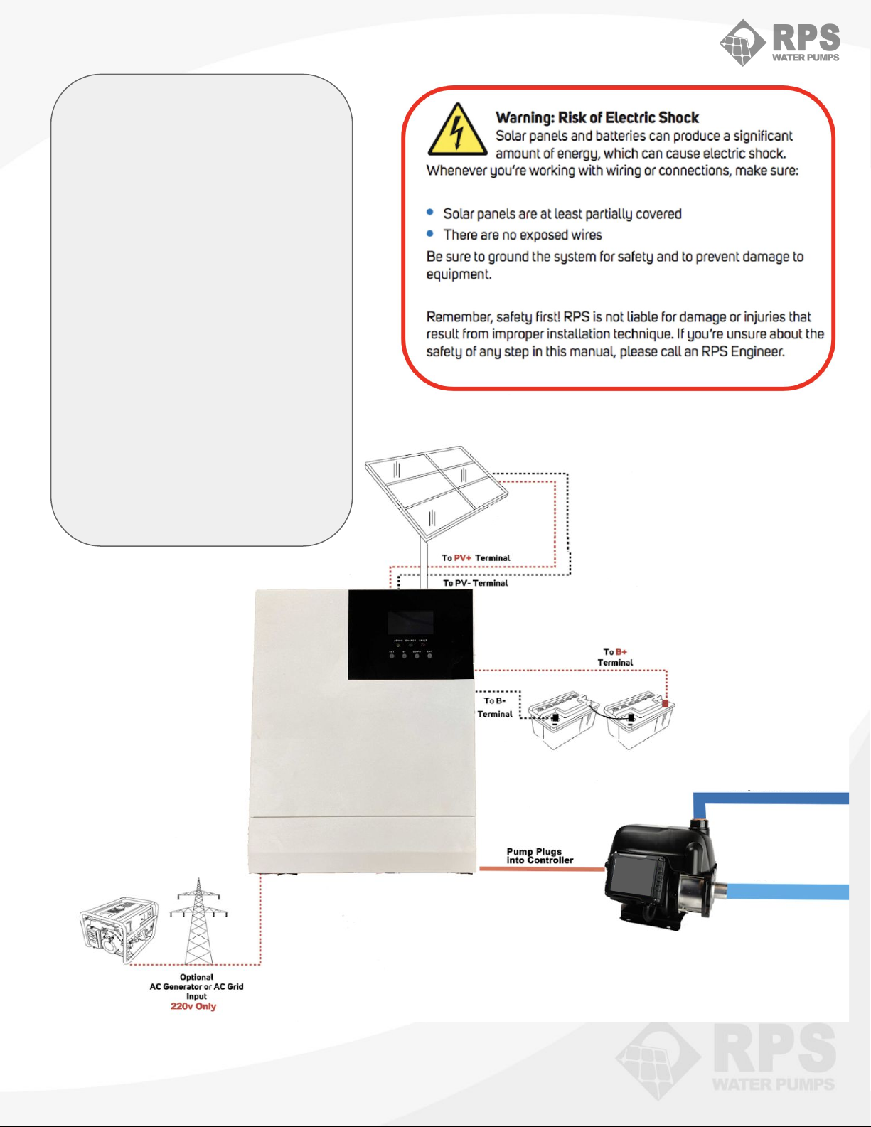
Solar Power Train Controller — Your Controller is not waterproof and should be located in a dry
dust-free location, protected from the sun and the elements and pests such as mice and bugs. Mice love
to chew wires and spiders and moths will build nests wherever they can find room. While we
understand you cannot eliminate all pests, it might be time to spray some insecticides around your
shed and set some mousetraps! There is nothing worse than finding insulation chewed off your
electrical wires. *The fan remains running in low power mode at all times to protect the equipment. This
fan uses very little power and it running, increases the lifetime of the system.
Tankless Pressure Pump or Eco-Steady Booster Pump - Your pump is designed for use out of the
direct elements, sun, rain and snow. Covering or building into a small enclosure is ideal. Since water
does expand when it freezes, care should be taken to winterize the system if being used in a climate
that experiences hard freezing. If foot valve is being used, care should be taken in plumbing the intake
to ensure tight connections which will avoid the loss of prime.
Batteries - Unless you already bought a system that included the appropriate number of RPS Deep
Cycle batteries, customers will need to supply their own battery bank. RPS recommends 12V AGM /
GEL / sealed lead acid batteries that are designed for maintenance free operation. More common
flooded deep cycle marine or RV batteries can also be used. Batteries should be stored in a dry location
protected from the elements. See page on wiring batteries.
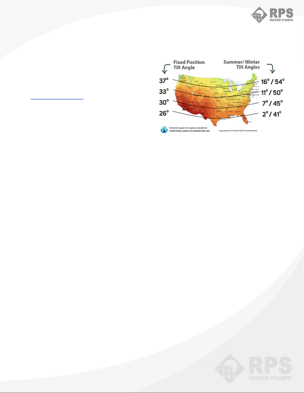
SOLAR PANELS — Solar panels should be
mounted on a secure structure, ground mount
or top of pole mount. Several ideas can be found
at RPSSolarPumps.com. Panels should face true
South and at an angle appropriate for your
latitude. If you are mounting your panels on an
already built structure, try to get as close to the
correct angle as possible.

RPSwaterpumps.com
PLUMBING OPTIONS
* Important: Care
should be taken when
plumbing to ensure
tight connections and
maintain prime. Use
teflon tape or thread
sealant (recommended)
on all connections.
Minor leaks or seepage
will cause the pump to
cycle and deplete the
batteries.
Pressure Pumps can plumb directly
from your storage tank to your main line.
It will auto-adjust speed and power
usage to maintain the set pressure.
You can also draw water up from a pond,
shallow well or cistern (up to 15ft) but
you must maintain prime with a
foot-valve and tight connections.

RPSwaterpumps.com
With both the RPS Tankless
Pressure Pump™ and
Eco-Steady Booster
Pumps™ you'll get smooth
continuous, steady, reliable
water pressure without the
need for AC power or the
utility grid.
The solar charged battery
bank powers your pump
through your Solar Power
Train™. The pump varies its
speed and power based on
your demand for water at the
exact pressure you select,
20psi and up! Quick Connect MC4 clips and
20’ of solar wire allow for the
connection of your solar
array to your controller
Pre-attached + and -
wires connect the
controller to your
24V battery bank
(48V for BP2, BP3)
Once the pump is ready for
power/primed with water,
the pump’s 3-prong male
plug can be inserted
directly into the outlet of
the controller.
(Optional) AC power
from a generator or
the grid can
supplement solar in
charging the battery
bank.
Solar
Power Train™
OUTLET
INLET

RPSwaterpumps.com
Eco-Steady
Booster Pump
BP05
High Pressure
Tankless
Pressure Pump
TPP-HP
Original
Tankless
Pressure Pump
TP750
Original
Eco-Steady
Booster Pump
BP2
Eco-Steady
Booster Pump
BP3
Max
Pressure 30psi 55psi 40psi 60psi 70psi
Volume 5-15 GPM 5-20 GPM 15-25 GPM 10-30 GPM 20-50 GPM
Pump Inlet
(FNPT) 1” 1-¼” 1-¼” 1-¼” 1-1/2”
Pump
Outlet
(FNPT)
1” 1” 1” 1” 1-1/2”
Horse-
power at
Max Power
0.5hp 1hp 1hp 2hp 3hp
Solar
Power
Train™
Model
VC3.11 VC3.22
VC3.11
Or
VC3.22
VC5.22 VC5.22
Input
Voltage
(optional)
110V-
120V
220V-
240V
220V-
240V
220V-
240V
220V-
240V
Battery
Bank
Voltage
24V 24V 24V 48V 48V
MODEL DETAILS

RPSwaterpumps.com
1. Loosen Priming Screw.
2. Create positive pressure in supply line to push
water into pump inlet or fill line with water
3. Once air is completely purged, power on the
pump to purge air completely before fully
tightening Priming Screw again
4. Adjust Pressure Setting with controls. Pump
will adjust speed and smoothly cycle on & off to
maintain desired setting.
BP05, BP1-HP, TPP-HP PRIMING
1. Loosen Priming Screw.
2. Create positive pressure in supply line to push
water into pump inlet or fill line with water
3. Once air is completely purged, power on the
pump to purge air completely before fully
tightening Priming Screw again
4. Adjust Pressure Setting with controls. Pump
will adjust speed and smoothly cycle on & off to
maintain desired setting.
NEW: Wire Priming ‘hook’ in the kit allows
you to reach into the top outlet of the pump
and pull up the small ring on the check
valve so you can pour water in the top and
fill the chamber easily.
PRIMING VIDEO for TP750
http://www.youtube.com/c/RPSSolarPumps
BP1, TP750 PRIMING
Priming
Screw
PRIMING THE PUMP

RPSwaterpumps.com
ASSEMBLY
** With stainless steel connections, RPS engineers and past
customers recommend Thread Sealant and large wrenches.
1) First thread your Tee with Pressure Sensor to the upper
outlet of the pump chamber using ample pipe dope/thread
sealant.
2) On the left and right sides of the Tee are two openings for
small fittings. On one side goes the closed fitting. On the other
side you remove the sensor from the small metal fitting, screw
the fitting tight, and then reattach the sensor plug to the pump
control interface.
3) The top of the tee is where the tank will go. Spin on the tank
until tight using ample pipe dope/thread sealant.
4) The tank is assembled and ready for you to add your inlet
and outlet connections. Remember to use adequate pipe dope
to ensure a tight, leak proof connection between fittings.
PRIMING
1. Loosen Priming Screw.
2. Create positive pressure in supply line to push water into
pump inlet or fill line with water
3. Once air is completely purged, power on the pump to purge
air completely before fully tightening Priming Screw again
4. Adjust Pressure Setting with controls. Pump will adjust
speed and smoothly cycle on & off to maintain desired setting.
1. Loosen Priming Screw.
2. Create positive pressure in supply line to push
water into pump inlet or fill line with water
3. Once air is completely purged, power on the
pump to purge air completely before fully
tightening Priming Screw again
4. Adjust Pressure Setting with controls. Pump
will adjust speed and smoothly cycle on & off to
maintain desired setting.
BP2 PRIMING
BP3 ASSEMBLY
& PRIMING
Priming
Screw
Pressure Regulation Tank
Tee with
Pressure
Sensor
Control Panel
Pressure
Sensor
INLET
PRIMING THE PUMP

RPSwaterpumps.com
TP/BP- 4
TP/BP- 8
VC3 & VC5 Series
You will link your solar panels together and
connect to the controller by clipping MC4
connectors together. Each MC4 connector is
either a male end or female end (see image). They
simply snap together to make safe
and easy connections.
Note: If using your own solar
panels do not exceed 90Voc
input for the VC3 and do not
exceed 145 Voc for the VC5! Ask
an RPS Engineer how to wire if
you’re unsure!
TP/BP- 12
WIRING SOLAR PANELS

RPSwaterpumps.com
VC3.22 & VC3.11 Solar Power Train™
BATTERY WIRING 24V (TP750 & BP1)
RPS recommends AGM / sealed lead acid batteries that are designed for several maintenance free
years of operation. They should also be stored in a dry location protected from the elements. To
prevent significant voltage drop, the batteries should be located as close to the Controller as possible.
Within 3 feet is ideal. If further than 3ft is required, the wires may be extended using appropriate
gauge cables. The batteries operate best at room temperature and it is best to keep them out of
freezing conditions for maximum performance.
Note: Do not exceed two 12V batteries in
series or four 6V batteries in series. For
extra battery capacity add sets in parallel.
WIRING BATTERIES

RPSwaterpumps.com
RPS recommends AGM / sealed lead acid batteries that are designed for several maintenance free
years of operation. They should also be stored in a dry location protected from the elements. To
prevent significant voltage drop, the batteries should be located as close to the Controller as possible.
Within 3 feet is ideal. If further than 3ft is required, the wires may be extended using appropriate
gauge cables. The batteries operate best at room temperature and it is best to keep them out of
freezing conditions for maximum performance.
Note: Do not exceed four 12V batteries in
series or eight 6V batteries in series. For
extra battery capacity, add sets in parallel as
shown above.
VC5.22 Solar Power Train™
BATTERY WIRING 48V (BP2 & BP3)
WIRING BATTERIES

RPSwaterpumps.com
Solar Power Train DISPLAY
The factory settings of
the Solar Power Train™
accommodates almost
every install scenario.
RPS Engineers
recommend leaving
them at their
programmed settings to
ensure proper
operation.

RPSwaterpumps.com
AC INPUT (Only if Required)
Your Controller is designed to take solar power and charge your battery bank. As an optional
backup, it is also setup to accept 220V to both charge your batteries and run your pump directly
if desired. (15A breaker) AC input can be wired directly into the screw terminals of your
controller, by removing the front cover plate. On some models you may find a pre-wired plug.
DISPLAY DETAILS
DEFAULT
Hybrid Mode

RPSwaterpumps.com
PUMP MODES
MODE to select the working mode:
1. NORMAL (most common)
Increases the water pressure or draws water up
from below pump and pressurizes. This is the
normal booster pump application.
1.0 - 2.0 Low Pressure
2.0 - 3.0 Medium Pressure
3.0 - 4.0 High Pressure
1 kg/cm² = 14.5 psi
Note: Pump shutoff will become unstable if
pressure is set too high. If pump will not shut-off,
reduce pressure setting
2. BOOST
Increases poor water pressure. For example
increasing 20 PSI water pressure to 45 PSI on a the
second story of a house.
3. TIMER
Operates for the specified amount of time and then
stops the pump. Used for filling elevated tanks.
BP1, BP2, LOCK / UNLOCK Hold UP and
DOWN arrows together
SYSTEM RESET OPTIONS:
POWER RESET:
Controller Soft Reset: Turn off controller power button (display will stay on if solar panels
are connected), wait 60 seconds and turn power button back on.
Controller Hard Reset: Disconnect solar panels and batteries. Wait 60 seconds, connect
batteries, then solar panels.
Pump Hard Reset: Unplug pump, wait 60 seconds, plug pump back in.
PUMP SETTINGS RESET:
Pump Factory Reset: Press and hold MODE for 3 seconds, all factory parameters will be
restored to factory settings.
TP750 - LOCK / UNLOCK
Hold + and - together
ADD 110V, TPP
AND 3HP
DISPLAYS!

RPSwaterpumps.com
** On the LCD screen, press the “UP” and “DOWN” buttons to scroll through
the real-time data of the controller unit!
Solar Power Train
DISPLAY PARAMETERS

RPSwaterpumps.com
Solar Power Train
TROUBLESHOOTING
Your Controller is not waterproof and should be located in a dry dust-free location,
protected from the sun and the elements and pests such as mice. moths and bugs. Mice love to
chew wires and spiders and moths will build nests wherever they can find room. While we
understand you cannot eliminate all pests, it might be time to spray some insecticides around
your shed and set some mousetraps! There is nothing worse than finding insulation chewed off
your electrical wires or moths clogging the units fan.
*The fan remains running in low power mode at most times to protect the equipment. This fan uses
very little power and it running, increases the lifetime of the system.
VOLTAGE CHECK
Take a DC Voltage
Reading of each battery.
Battery voltages range
from 11.5VDC
(dangerously low) to
14.4VDC (fully charged)
depending on the state of
charge. Low voltages?
Charge for 8 hours in full
sun.
SOFT RESET
Press and Release Power
Switch
HARD RESET
Disconnect Batteries and
Solar Panels for 60
seconds. Reconnect.

RPSwaterpumps.com
PUMP TROUBLESHOOTING
No Lights On Pump Low or no power
To pump
Check Connections, Soft Reset of Controller, Check batteries for
low voltage
Pump Doesn’t Start Pipe is
blocked Ensure valves are open to clear airlocks
Pump Doesn’t Stop Check for leaks, Turn down
pressure
Small leaks in plumbing are the most common, check around
outlet cover, Turn down pressure setting
Pump Sputters Pump not properly primed or
air entering system
Prime pump and remove all air from system, check inlet pipes for
leaks, Install foot valve for suction applications
Settings may have been
changed Reset to factory defaults Press and hold “MODE” for three seconds
E01 Low input voltage Check input voltage, Check battery voltage
E02 Over voltage input Ensure input voltage is less than 140V AC
E03 Pressure sensor error Hard Reset, Replace pressure sensor
E04 Pump over temperature Remove pump from direct sun, Improve ventilation
E05 Pump Overload Ensure water is fairly clear (no mud or large debris)
E06 Display over temperature or
sensor failure
Remove from direct sun, Improve ventilation, Hard reset, Contact
RPS
E07 Not Used n/a, Hard Reset
E08, E09 Motor phase mismatch, Over
current
Motor not operating at commanded speed, check for obstructions,
check for stuck impellers
E10 Startup fault Hard Reset, Contact RPS to check for impeller obstructions
E11 Motor communication error Check for damage to motor wires, Hard Reset, Contact RPS
E12 Not used n/a, Hard Reset
E13 Display communication error Hard Reset, Contact RPS
Hard Reset
Unplug pump, wait 60 seconds,
plug pump back in.

RPSwaterpumps.com
Inlet 1" FNPT Power Range XXXX w
Outlet 1" FNPT Suction Up to 4M, 15ft (wetted)
Acceptable pH 5 - 8, Water (No Fuel) Max Current 6 Amps
Temp. Range 0 - 40°C, 32 - 104°F Pump Dimensions
Box Size
17in x 9in x 11in
19in x 11in x 13in
Max Liquid Temp 90°C, 194°F Weight XXXXkg, XXXXlbs
BP05 PUMP SPECS
REPLACE

RPSwaterpumps.com
Inlet 1" FNPT Power Range 750 - 1500w
Outlet 1" FNPT Suction Up to 4M, 15ft (wetted)
Acceptable pH 5 - 8, Water (No Fuel) Max Current 8 Amps
Temp. Range 0 - 40°C, 32 - 104°F Pump Dimensions
Box Size
17in x 9in x 11in
19in x 11in x 13in
Max Liquid Temp 90°C, 194°F Weight 10kg, 22lbs
TPP-HP / BP1 PUMP SPECS
TP-750 SPECS
Inlet 1.25" FNPT Power Range 750 - 1500w
Outlet 1" FNPT Suction Up to 4M, 15ft (wetted)
Acceptable pH 5 - 8, Water (No Fuel) Max Current 8 Amps
Temp. Range 0 - 40°C, 32 - 104°F Pump Dimensions
Box Size
14in x 12in x 9in
15in x 13in x 11in
Max Liquid Temp 90°C, 194°F Weight 10kg, 22lbs
This manual suits for next models
5
Table of contents
Other RPS Water Pump manuals
Popular Water Pump manuals by other brands

tecan
tecan cavro xlp 6000 operating manual

Circor
Circor HOUTTUIN 216 Series ORIGINAL INSTALLATION, OPERATION AND MAINTENANCE MANUAL

SKF
SKF Lincoln P 215 Series Assembly instructions

BUSCH
BUSCH R5 KB 0010 E instruction manual

WDM
WDM NE Series Operation manual

Alfa level
Alfa level 3S Series instruction manual

Annovi Reverberi
Annovi Reverberi AR 245 LFP instruction manual

Star
Star 025576 quick start guide

Neptun
Neptun NKP-E 22 Original operating instructions

Action
Action P490 Operating instructions & parts manual

SKF
SKF PTEX operating manual

yellow jacket
yellow jacket SuperEvac PLUS II Operation and maintenance manual