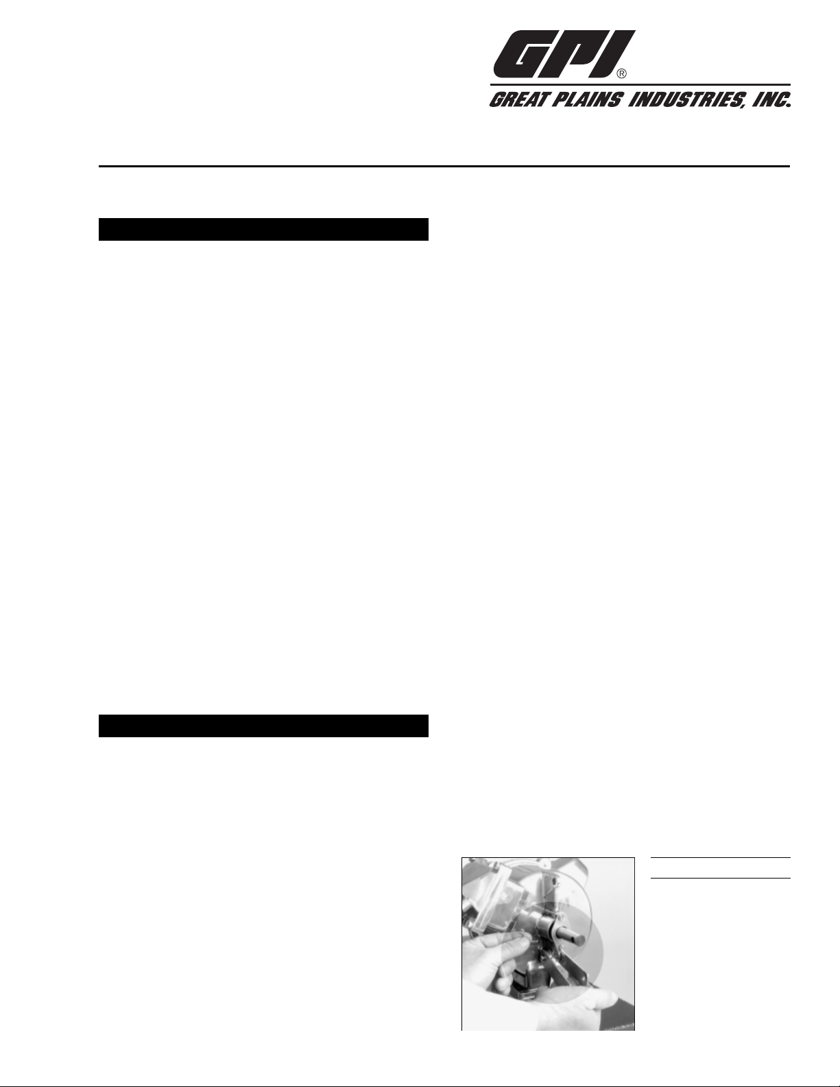
GREAT PLAINS HP-100 Dual-Flo User manual

The GPI HP-100 DUAL-FLO
®
Petroleum Hand Pump is de-
signed to manually pump petroleum products compatible
with aluminum and Buna-N. The user has the flexibility of
operating the pump at two flow rates. A setting of 1/2-gallon
provides faster high-capacity flow. A 1/4-gallon setting al-
lows for easier pumping of fluids. The HP-100 Hand Pump is
designed for use on a tank with a 2-inch bung.
Read Me!
Observe standard precautions when handling fuel.
•Keep fuel away from open flame or spark.
•Do not refuel vehicles or equipment with engines running
or while equipment engine is hot.
•Do not smoke while refueling.
Use the HP-100 Hand Pump only with petroleum products
such as diesel fuel, kerosene, and gasoline. This equipment
should not be used to pump chemicals.
Damage Inspection
Upon receipt of your pump system, carefully inspect visible
components for any damage that may have occurred during
shipping. Note that the pump includes a suction pipe, dis-
charge hose, and nozzle. If any parts are damaged or
missing, please contact your distributor.
GENERAL INFORMATION
HP-100 Dual-Flo
®
Petroleum Hand Pump
Owner’s Manual
Use the following procedures to install the HP-100 Hand
Pump on a tank with a 2-inch bung.
Install Suction Pipe
1. Remove the two protective plugs from the pump inlet and
outlet ports.
2. Wrap the threaded end of the suction pipe with 3 to 4 turns
of Teflon
®
tape.
3. Insert the suction screen into the inlet cover.
4. Place the spacer in the inlet cover to secure the inlet screen.
5. Install the suction pipe into the inlet cover and tighten
firmly with a pipe wrench.
INSTALLATION
5252 East 36th Street North
Wichita, KS USA 67220-3205
TEL: 316-686-7361
FAX: 316-686-6746
“A Great Plains Ventures Subsidiary”
www.gpi.net
1-800-835-0113
Rev. - 921407-0911/02
Figure 1
Install Pump on Tank
1. Before installing the pump, clean the tank interior of all dirt
and foreign material.
2. Lubricate the threads of the inlet cover with Teflon
®
tape
or a thread-sealing compound approved for use with
petroleum fuels.
3. Extend the adjustable suction pipe to its full length and
carefully insert it into tank opening. The suction pipe will
adjust to the length needed and rest on the bottom of tank.
NOTE: The suction pipe supplied has a variable length of 22
to 40 inches. If additional length is needed, order the 15-
inch Suction Pipe Extension Kit.
4. Thread the inlet fitting of the pump onto the tank and turn
the pump to tighten snugly.
NOTE: To prevent the buildup of pressure and possible fuel
leakage through the nozzle, make sure the tank is vented.
Install Hose and Nozzle Assembly
Apply 3 to 4 wraps of Teflon
®
tape to the threaded end of the
hose and hand-tighten into the outlet cover until snug.
Install Handle
The HP-100 Hand Pump gives the operator a choice of two
flow settings:
•1/4 gallon setting has low resistance and pumps 1/4
gallon per stroke cycle.
•1/2 gallon setting has higher resistance and pumps 1/2
gallon per stroke cycle.
Volume per stroke is determined by connecting the piston
shaft to the appropriate handle setting as outlined below.
NOTE: Clevis pins may be installed from either side of handle.
1. Slide the handle grip onto the pump handle.
2. To install the links on the pump, insert a long clevis pin
through the link ends and the pump’s link holes. Secure
with a small cotter pin. (Figure 1)

4. Insert a screwdriver in the piston shaft of the pump and
pull the piston out. Install the shaft on the handle at either
piston hole by placing a short clevis pin through the handle
and the piston shaft end and securing with the hitch clip pin.
NOTE: Select the upper piston hole on the handle for the 1/2-
gallon setting (Figure 3) or the lower piston hole for the
1/4-gallon setting. Flow settings can be changed at any
time by repositioning the piston shaft on the handle.
To Dispense Fluid
1. Remove the nozzle from its holder and insert into the
receiving tank of the equipment or vehicle.
2. Choose a handle setting for the desired flow rate:
–1/4-gal. setting for low-volume, low-resistance pumping
–1/2-gal. setting for high-volume, high-resistance pumping
3. To operate pump, manually move the handle in a push/
pull motion.
4. After dispensing the desired amount of fluid, drain the
hose and nozzle. Place the nozzle in its holder and return
the handle to its upright storage position.
During daily use, the GPI HP-100 Hand Pump is essentially
maintenance free. However, the pump should be inspected
periodically for signs of leakage. If leaks are present, make
appropriate repairs. Refer to the Troubleshooting section.
Figure 2
Figure 3
Figure 4
OPERATION & MAINTENANCE
NOTE: Lock the handle to the pump by pushing the handle
against the pump and inserting a padlock through either
of the top holes in the handle and through the pump’s lock
hole. (Figure 4)
SYMPTOM PROBABLE CAUSE CORRECTIVE ACTION
A. FLUID LEAKS AROUND 1. Packing seals settled Tighten two screws on the retainer and torque to approximately 20 lb. in. (or hand
SHAFT SEAL tighten then another half turn until leak stops)
2. Seals worn Remove the two screws on the retainer and remove the retainer and bearing. Remove
all three seals and replace.
B. FLUID LEAKS AT 1. Anti-siphon valve or Replace vent plug assembly. Remove the black cap. Remove old vent plug assembly
ANTI-SIPHON VALVE O-ring damaged by turning counterclockwise. Install new vent plug assembly. Replace cap.
C. LOW FLOW RATE 1. Inlet screen clogged Remove the pump from the tank. Remove the suction pipe, spacer, and inlet
screen from the bottom of the pump. Clean the inlet screen and assemble. Place
the pump on the tank using installation instructions.
2. Suction pipe leak Remove the pump from the tank. Inspect the spacer and suction pipe to ensure
they are not worn or damaged. Replace as necessary and install the suction pipe
and pump again using installation instructions.
3. Piston ring or liner Remove the piston cover and inspect the piston ring and liner. Scoring and
worn severe scuffing on the liner indicates wear. If necessary, install an Overhaul Kit.
4. Piston cracked Remove the piston cover and inspect the piston. Install an Overhaul Kit, if necessary.
D. PUMP SEIZED 1. Debris in piston or Disassemble and clean the piston and liner. Check for debris lodged in the
liner piston ring or behind the liner. Small dimples in the liner indicate dirt, debris or
welding slag contaminants in the tank. Replace the piston ring and liner. If
appropriate, flush the tank of all contaminants.
TROUBLESHOOTING
Attach links to first hole
Use for 1/2 gallon setting
Use for 1/4 gallon setting
➤➤
➤➤
➤➤
1/2 gallon setting
shown here
➤➤
3. Attach the free ends of the links to the bottom, outer
surfaces of the handle. Insert a long clevis pin through the
holes on both links and the lowest hole on the handle.
Secure with a small cotter pin. (Figure 2)

A
A
A
ILLUSTRATED PARTS DRAWING
Kits and Accessories
114510-3 Hardware Kit includes handle grip, links, pins, and
screen.
114505-2 Overhaul Kit includes piston ring, three seals, pack-
ing seals, and liner.
114509-1 Inlet Cover Kit includes inlet cover, spacer, and
screen.
115527-2 Suction Pipe Extension, 15 inches.
Item No.n
No. Part No. Description Req’d.
114510-3 Hardware Kit ( ) ........................... 1
2 114014-2 Handle ............................................. 1
8904004-30 Screw, hex head, 10-32 x 5/8 in...... 2
9 114017-2 Retainer ........................................... 1
10 114016-1 Bearing ............................................ 1
13 114034-1 Packing Seal or (Kit ) .................. 3
14 114042-1 Body ................................................ 1
15 114009-1 Spring .............................................. 4
16 114007-1 Plate ................................................. 2
17 114008-1 Valve ................................................ 4
18 114043-4 Outlet Cover, 3/4 in. ........................ 1
19 904002-23 Screw, sems, 1/4-20 x 3/4 in......... 14
20 114006-1 Seal or (Kit ) ................................ 2
21 123504-1 Anti Siphon Vent Kit......................... 1
23 114041-1 Piston Cover .................................... 1
24 901001-51 Cover Seal or (Kit ) ...................... 1
25 906005-58 Piston Ring or (Kit ) ..................... 1
26 114021-1 Piston Assembly .............................. 1
27 114011-1 Liner or (Kit ) ............................... 1
32 114509-1 Inlet Cover Kit ( ) ......................... 1
34 114037-1 Inlet Screen or (Kit ) .................... 1
35 114038-1 Spacer or (Kit ) ............................ 1
36 110100-1 Adjustable Suction Pipe, 22-40 in. .. 1
37 114504-3 Hose and Nozzle Assembly Kit ....... 1
A
B
C
AA
B
B
B
B
C
C
C
B

The HP-100 DUAL-FLO
®
Petroleum Hand Pump is compat-
ible with a wide variety of petroleum products and fits any
container with a 2-inch NPT bung.
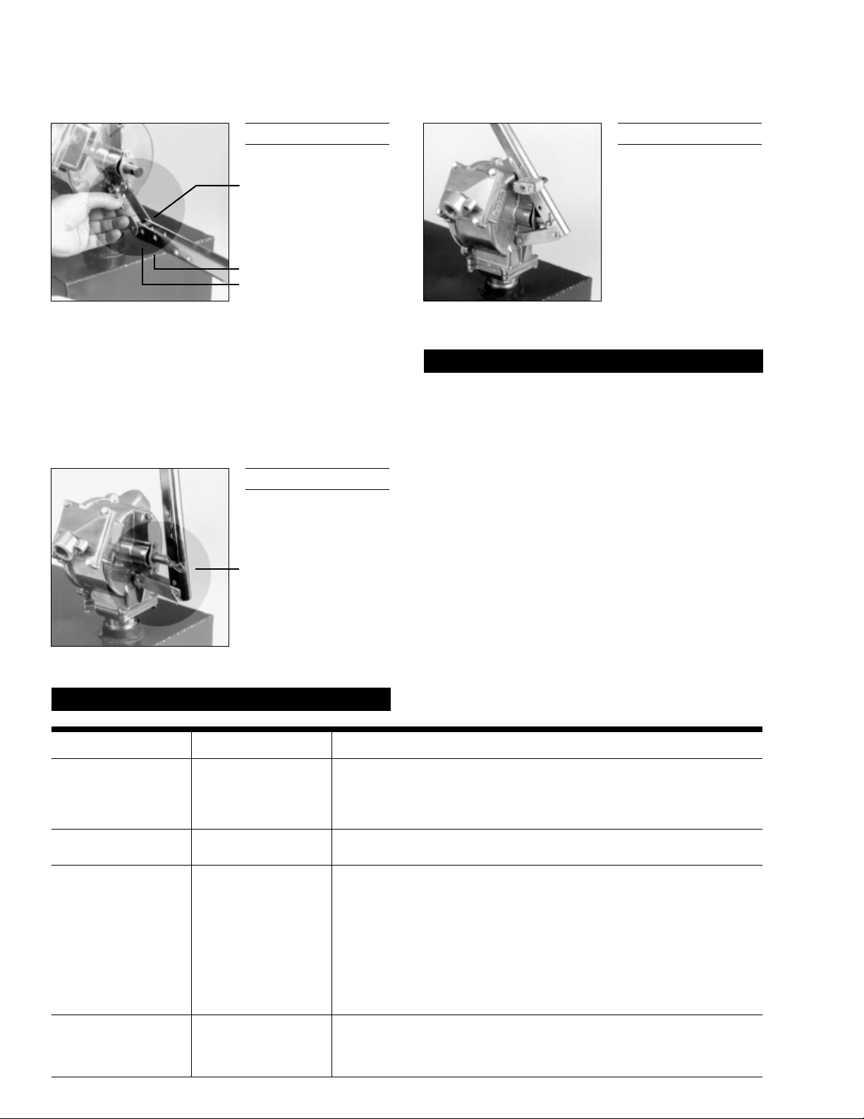
Construction Lightweight, die-cast aluminum hous-
ing. Stainless steel piston shaft and
liner. Buna-N seals. Built-in air valve to
prevent leakage at the nozzle.
Pumping Capacity 1/2 gallon (1.9 litres) per stroke cycle.
Pumping Settings 1/2 gallon setting for high volume, high
resistance.
1/4 gallon setting for low volume, low
resistance.
Inlet Standard 1-inch NPT pipe.
Outlet Standard 3/4-inch NPT pipe.
Shipping Weight 14 lbs.
Hose and Nozzle 3/4 inch x 8 foot Buna-N hose. Thermo-
plastic unleaded nozzle. Built-in nozzle
holder.
Suction Pipe Plastic, adjustable 22 to 40 inches.
For warranty consideration, parts or other service informa-
tion, please contact your local distributor or the GPI Cus-
tomer Service Department in Wichita, Kansas, during normal
business hours.
1-800-835-0113
To obtain prompt, efficient service, be prepared with the
following information:
•The model number of your pump.
•The manufacturing date of your pump.
•Part descriptions and numbers.
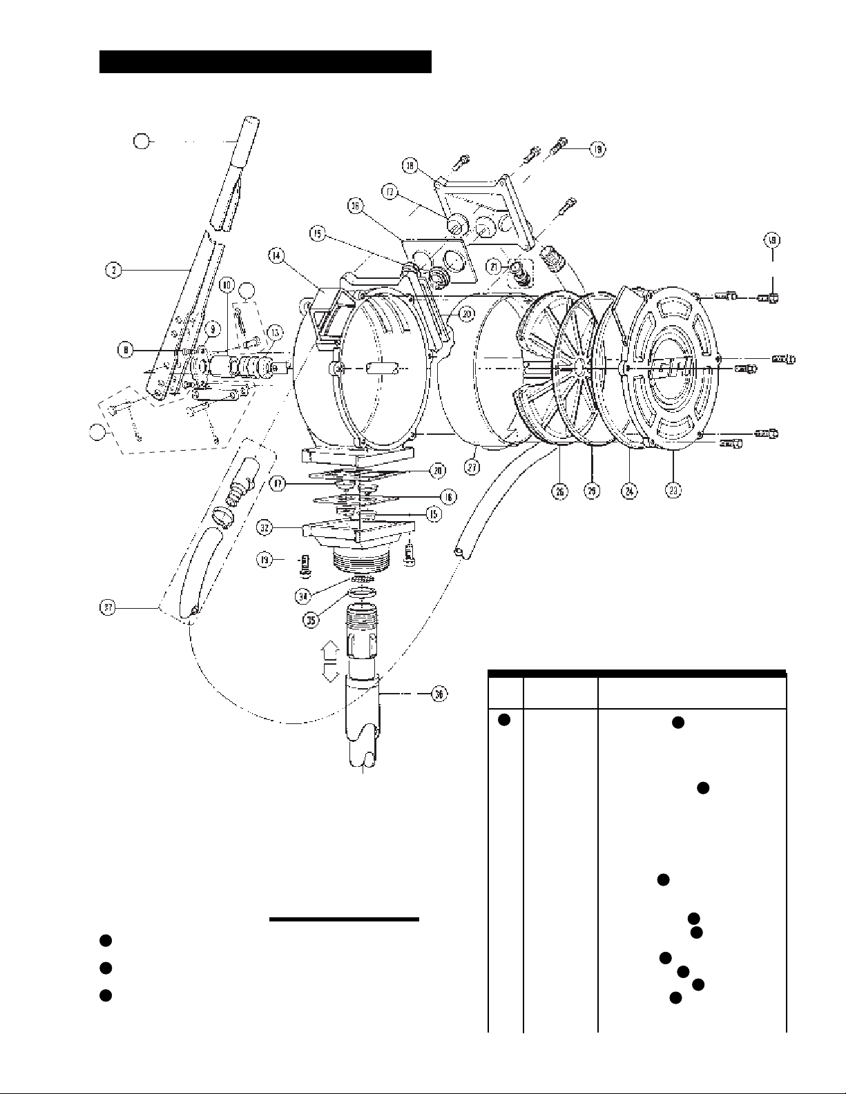
Part descriptions and numbers can be obtained from the
Illustrated Parts Drawing.
For warranty service, be prepared with your original sales slip
or other evidence of purchase date.
U.S. Patent D 308,567
Dual-Flo and GPI are registered trademarks of
Great Plains Industries, Inc.
© 2002 by GREAT PLAINS INDUSTRIES, INC., Wichita, KS
Printed in U.S.A.
SPECIFICATIONS PARTS AND SERVICE
5252 East 36th Street North
Wichita, KS USA 67220-3205
TEL: 316-686-7361
FAX: 316-686-6746
“A Great Plains Ventures Subsidiary”
www.gpi.net
1-800-835-0113
Rev. - 921407-0911/02
Limited Warranty Policy
GreatPlains Industries,Inc.5252 E.36
th
Street North,Wichita,KS USA67220-3205,hereby providesalimited twoyearwarranty against
defects in material and workmanship on all products manufactured by Great Plains Industries, Inc. except models BP-10, BP-12, CP-5,
D-12, D-24, D-115, D-230, LP-50 and RP-5. These models carry a 90-day warranty. The warranty shall extend to the purchaser of this
product and to any person to whom such product is transferred during the warranty period.
The warranty period shall begin on the date of the original new equipment purchase. Warrantor’s obligation hereunder shall be limited to
repairing defective workmanship or replacing or repairing any defective part or parts. This warranty shall not apply if:
A. the product has been altered or modified outside the warrantor’s duly appointed representative;
B. theproducthas beensubjectedtoneglect, misuse,abuseordamage or hasbeeninstalledor operatedotherthanin accordance
with the manufacturer’s operating instructions.
To make a claim against this warranty, notice of claim must be given in writing to the company at its above address no later than 30 days
aftertheexpirationofthe warranty period.Suchnoticeshallidentifythedefectin theproduct.Thecompanyshall,within14daysof receipt
of such notice, notify the customer to either send the product, transportation prepaid, to the company at its office in Wichita, Kansas, or
to duly authorized service center. The company shall perform all obligations imposed on it by the terms of this warranty within 60 days of
receipt of the defective product.
GREAT PLAINS INDUSTRIES, INC. EXCLUDES LIABILITY UNDER THIS WARRANTY FOR DIRECT, INDIRECT, INCIDENTAL AND
CONSEQUENTIAL DAMAGES INCURRED IN THE USE OR LOSS OF USE OF THE PRODUCT WARRANTED HEREUNDER.
Thecompanyherewithexpresslydisclaimsany warranty ofmerchantabilityorfitnessforanyparticularpurposeotherthan for whichitwas
designed.
This warranty gives you specific rights and you may also have other rights which vary from U.S. state to U.S. state.
Note: In compliance with MAGNUSON MOSS CONSUMER WARRANTY ACT – Part 702 (governs the resale availability of the warranty
terms).
Table of contents
Other GREAT PLAINS Water Pump manuals
Popular Water Pump manuals by other brands

Norco
Norco 910052A instruction sheet

Judo
Judo PROMI-QC JPM-QC 1.5 Installation and operating instructions

Utile
Utile DSP25-5 Installation, operation & maintenance instructions

Grundfos
Grundfos TPE Series Safety instructions and other important information

Coral Box
Coral Box WF-04 instructions

Pentair
Pentair MYERS MS33PT owner's manual