Alfa level 3S Series User manual

ESE02461-EN1 2013-05
Original manual
Instruction Manual
Alfa Laval Three-Screw Pumps with Magnetic Coupling - 3S Series


Table of contents
The information herein is correct at the time of issue but may be subject to change without prior notice
1. EC Declaration of conformity ....................................................................... 5
2. Safety .................................................................................................... 6
2.1. Generel information ............................................................................... 6
2.2. Target groups ..................................................................................... 6
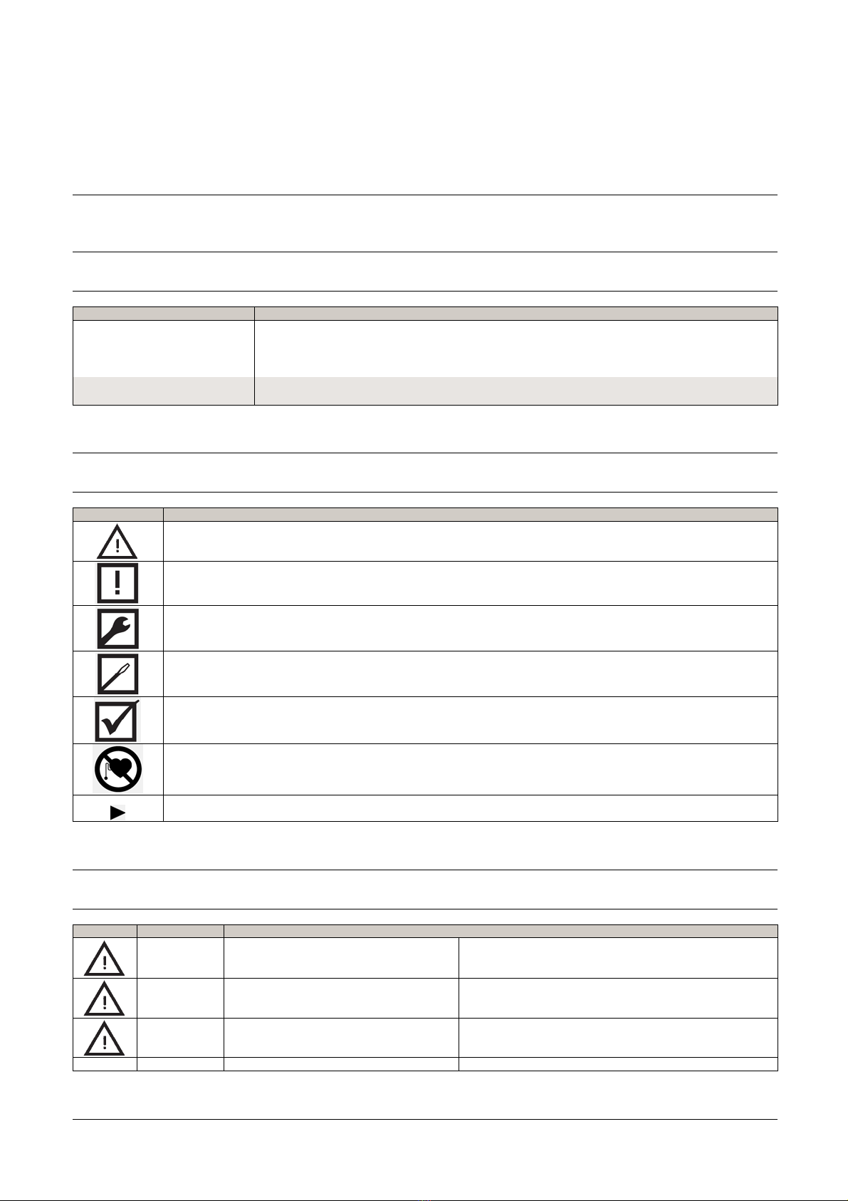
2.3. Symbols ........................................................................................... 6
2.4. Danger levels ...................................................................................... 6
2.5. Proper use ......................................................................................... 7
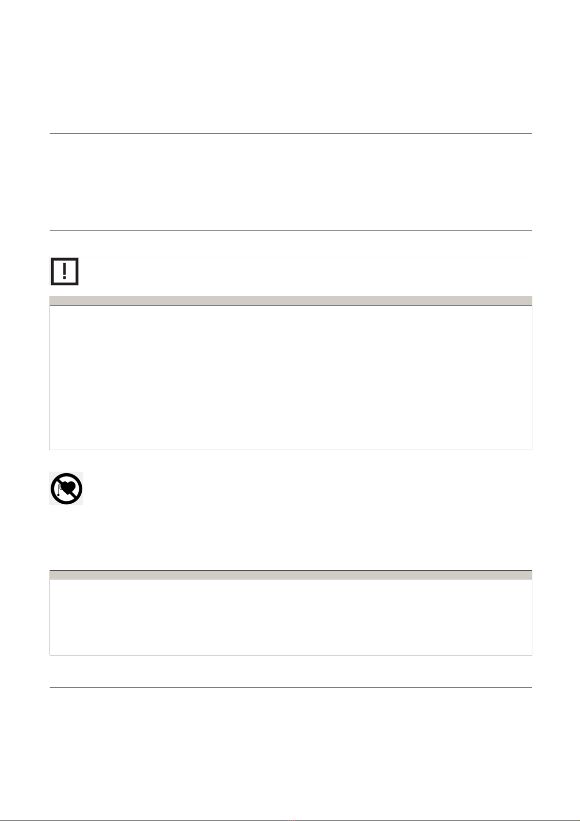
2.6. Safety information ................................................................................ 7
3. Installation .............................................................................................. 8
3.1. Unpacking and checking the state of delivery ................................................. 8
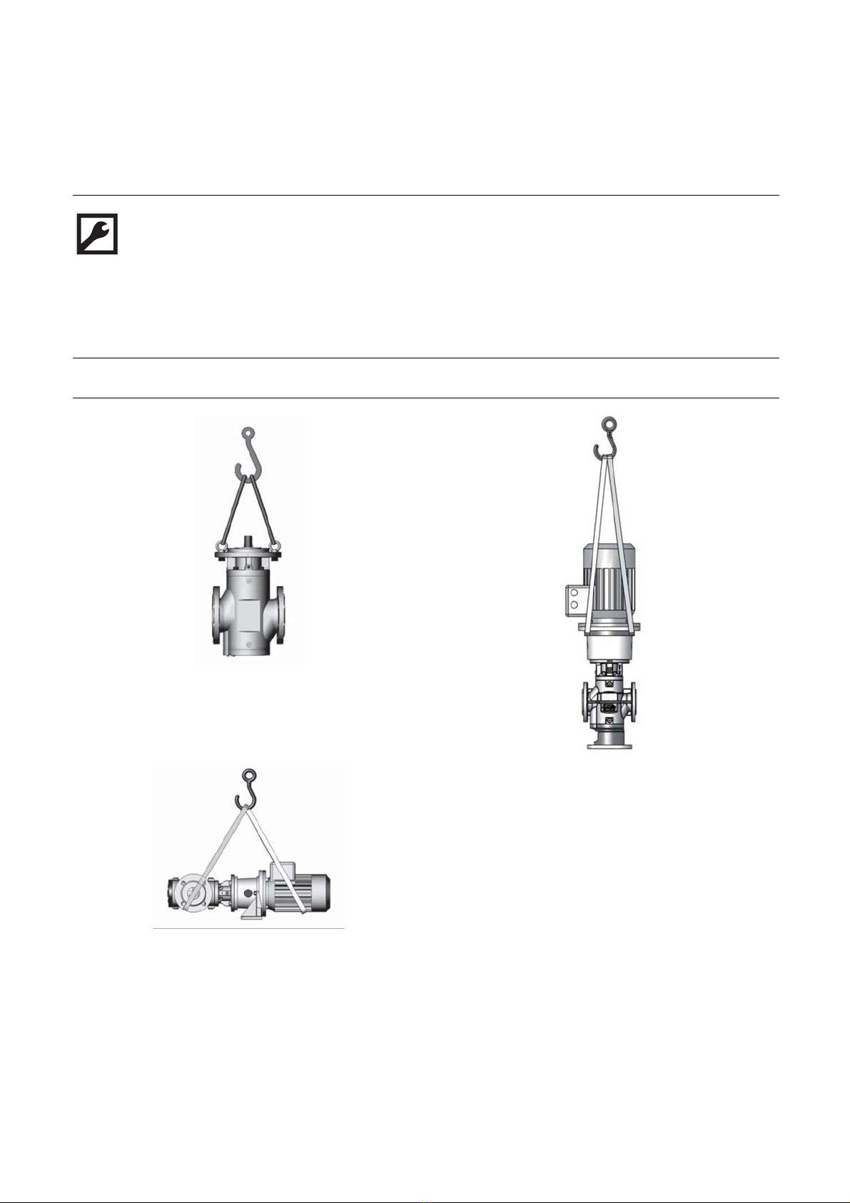
3.2. Lifting the pump/pump unit ...................................................................... 8
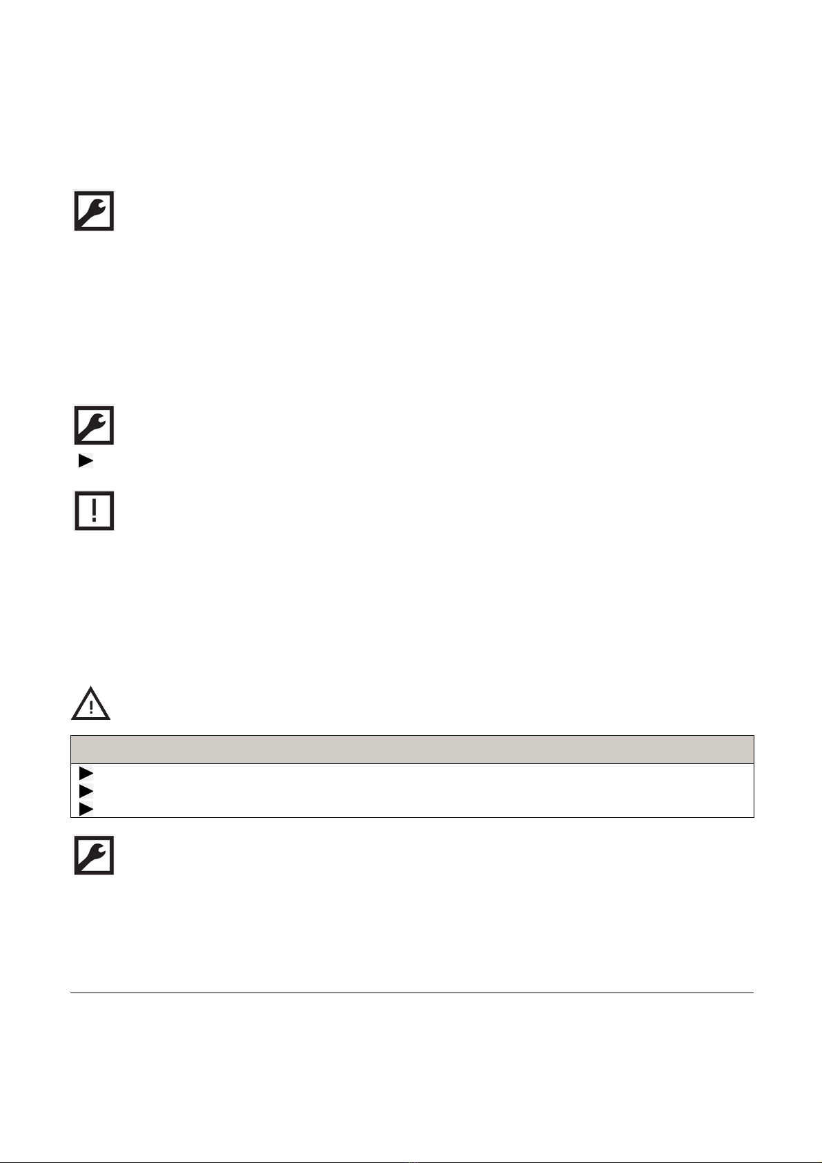
3.3. Storage ............................................................................................ 9
3.4. Preservation ....................................................................................... 9
3.5. Disposing of the pump ........................................................................... 11
3.6. Installation ......................................................................................... 12
3.7. Connecting the motor ............................................................................ 13
3.8. Removing the pump .............................................................................. 13
3.9. Heating system ................................................................................... 14
3.10.Electric heating system ........................................................................... 14
3.11.Fluid heating system .............................................................................. 16
3.12.Heating system special design .................................................................. 17
4. Operation ............................................................................................... 18
4.1. Commissioning .................................................................................... 18
4.2. During operation .................................................................................. 21
4.3. Taking the pump out of operation ............................................................... 22
4.4. Recommissioning the pump ..................................................................... 23
5. Maintenance ........................................................................................... 24
5.1. Safety instructions ................................................................................ 24
5.2. Required maintenance ........................................................................... 24
5.3. Replacing the magnetic coupling ............................................................... 25
5.4. Installing the magnetic coupling ................................................................. 27
5.5. Replacing the ball bearing and screw set ...................................................... 29
5.6. Possible faults ..................................................................................... 31
5.7. Troubleshooting ................................................................................... 31
6. Technical data ......................................................................................... 33
6.1. Type code ......................................................................................... 33
6.2. Name plate ........................................................................................ 34
6.3. Operating limits ................................................................................... 34
6.4. Sound pressure level ............................................................................. 34
6.5. Required NPSH values ........................................................................... 35
6.6. Weights ............................................................................................ 36
6.7. Structure ........................................................................................... 39
6.8. Housing variants .................................................................................. 40
6.9. Magnetic coupling ................................................................................ 41
6.10.Overflow valve ..................................................................................... 41
6.11.Tightening torques ................................................................................ 42
3

Table of contents
The information herein is correct at the time of issue but may be subject to change without prior notice
7. Spare parts ............................................................................................. 43
7.1. Maintenance sets ................................................................................. 43
7.2. Repair sets ........................................................................................ 48
7.3. Completions ....................................................................................... 53
4

1 EC Declaration of conformity
The designated company
Alfa Laval
Company Name
Albuen 31, DK-6000 Kolding, Denmark
Address
+4579322200
Phone No.
hereby declare that
Three-Screw Pump 3S 2013-05-01
Denomination Type Year
Is in conformity with
- Machinery Directive 2006/42/EC
and futhermore declares that if motorised the following applicable directives have been used
- Directive 2006/95/EC on low voltage
- EMC Directive 2004/108/EC
The technical construction file for this machinery has been drawn up. The signer of this declaration is authorized to compile the
technical file.
Manager, Product Center Fluid Handling Bjarne Søndergaard
Title Name
Alfa Laval Kolding
Company Signature
5

2 Safety
2.1 Generel information
The operating instructions form part of the pump/pump unit and must be kept for future reference. Furthermore please observe
the associated documents.
2.2 Target groups
Target groups Tasks
Operator - owner - Keep these instructions available at the system site for future reference.
- Ensure that employees read and observe these instructions and the associated documents,
in particular the safety instructions and warnings.
- Observe additional system - specific directives and regulations.
Specialist personnel, fitters - Read, observe and follow these instructions and the associated documents, in particular
the safety instructions and warnings.
2.3 Symbols
Symbol Meaning
Warning personal injury
Notice
Procedures mechanical installation
Procedures electrical installation
Chek or fault table
Safety instructions for persons with pacemakers
Request for action
2.4 Danger levels
Warning Danger level Consequences of non-observances
DANGER Immediate threat of danger Serious personal injury, death
WARNING Possible threat of danger Serious personal injury, invalidity
CAUTION Potentially dangerous situation Slight personal injury
CAUTION Potentially dangerous situation Material damage
6

2 Safety
2.5 Proper use
- Use the pump solely for transporting lubricating liquids that are chemically neutral and that contain no gas or solid
components.
- Use the pump only within the operating limits specified on the name plate and in the Chapter "Technical data". In the case of
operating data that does not agree with the specifications on the name plate, please contact the manufacturer.
- The pump is designed specially for the operating pressure named by the customer. If the actual operating pressure deviates
notably from this design pressure, damage can also arise within the specified operating limits. This applies both to notably
higher as well as to notably lower operating pressures. Under no circumstances should the operating pressure drop below
the minimum pressure of 2 bars. In case of any doubt, please contact the manufacturer.
2.6 Safety information
The following general safety instructions must be observed:
- No liability is accepted for damage arising through non-observance of the operating instructions.
A. Read the operating instructions carefully and observe them.
B. The operator-owner is responsible for the observance of the operating instructions.
C. Installation, removal and installation work may only be carried out by specialist personnel.
- In order for the warranty to remain valid, corrective maintenance carried out during the warranty period requires the express
permission of the manufacturer.
- Observe the general regulations for the prevention of accidents as well as the local safety and operating instructions.
- Observe the valid national and international standards and specifications of the installation location.
- In case of systems with an increased potential of danger to humans and/or machines the failure of a pump may not lead
to injuries or damage to property.
A. Always equip systems with an increased potential of danger with alarm equipment.
B. Maintain and check the protective/alarm equipment regularly.
- The pumped liquids can be dangerous (e.g. hot, dangerous to health, poisonous, combustible). Observe the safety
regulations for handling dangerous materials.
- Pumped liquids can be subject to high pressure and can cause damage and/or personal injury should leaks occur.
Safety instructions for magnetic coupling systems
Magnetic fields from magnetic coupling systems (MCS) can influence the function and operational safety of electrical and
electronic devices. The following safety instructions must be observed:
Additional safety instructions for magnetic coupling systems:
- Keep the MCS away from pacemakers. There is a danger to life!
A. Under no circumstances may persons with pacemakers perform installation, dismantling or maintenance work.
- Persons with pacemakers must comply with the following safe distances to the MCS:
A. 3 m distance to the openly accessible MCS.
B. 1 m distance to pump units with installed MCS.
- Do not bring the MCS in the immediate area of PCs, data carriers and other electronic components.
- Keep the MCS away from clocks, magnetized tools and measuring equipment as well as all magnetizable parts.
- Do not bring both the MCS parts together, as this can destroy the magnetic coupling system.
7

3 Installation
3.1 Unpacking and checking the state of delivery
1. On delivery unpack the pump/pump unit and check for damage during transportation.
2. Report damage during transportation immediately to the manufacturer.
3. Dispose of packing material in accordance with the locally applicable regulations.
3.2 Lifting the pump/pump unit
Fig. 1 Fastening hoisting equipment – Principle diagrams
8

3 Installation
DANGER
Risk of injury and/or damage to equipment should the pump/pump unit fall.
Use intact and correctly dimensioned hoisting equipment.
Attach the hoisting equipment correspondingly.
Secure motors additionally against tilting.
Do not stand under raised loads.
Pump
1. Screw eye bolts into two opposing holes at the flange cover, see Fig. 1, page 8.
2. Hang the slinging devices into the eye bolts.
3. Hang the crane hook into the slinging devices and lift the pump.
Pump unit
1. Model 3SBI: Fasten the slinging devices at the pump unit at an angle between 60° and 90°, see Fig. 1, page 8. Ensure
that the center of gravity of the pump unit lies between and below the attachment points. If this is not possible, take other
suitable measures to prevent the pump unit from tilting.
Model 3SVI: Sling the slinging devices around the pump bracket, see Fig. 1, page 8.
2. Secure the slinging devices against slipping, for example through screwed-in eye bolts.
3. Hang the crane hook into the slinging devices and lift the pump unit.
3.3 Storage
During the test run, the internal components of the pump are wetted with test oil, which has a preservative effect. The pipe
connections are fitted with protective caps. Unless otherwise specified, the external components of the pump are preserved
with a single-coat PU-based two-component paint. The preservative applied at the factory will protect the pump for about six
weeks, if it is stored in a dry and clean location. The manufacturer offers a long-term preservation for storage times of up to 60
months. The pump is additionally packed in hermetically sealing anti-corrosion paper.
3.4 Preservation
Preservation has to be carried out additionally under the following conditions:
Type of delivery Condition
Standard delivery - Storage time exceeding six weeks
- Unfavorable storage conditions such as high humidity, salty air, etc.
Delivery with long-term preservation - Opened or damaged packaging
Tab. 1 - Check table for preservation
9

3 Installation
Preserving the internal surfaces of the pump
1. Close the suction connection of the pump with a blind flange.
2. Pour non-corrosive, resin-free oil into the pressure connection until it reaches approx. 2 cm under the pressure flange, while
slowly turning the main screw against the direction of rotation.
3. Close the pressure connection of the pump with a blind flange.
After about six months storage check the oil level and if necessary top up oil.
Preserving the external surfaces of the pump
Aids:
- Preservative (e.g. Castrol Rustilo DWX 33)
Paint or spray the preservative onto all plain and unpainted parts.
At intervals of about six months check the preservation and if necessary repeat.
NOTE
Store the preserved pump cool and dry and protect it against direct sunlight.
Removing the preservation
Aids:
-Solvent
- Steam-jet cleaning device with wax-dissolving additives
CAUTION
Risk of injury through emitted preservative oil.
Wear protective clothing during all the work.
Open the blind flange carefully in order to reduce any pressure that may exist in the pump.
Collect the emitted preservative oil safely and dispose of it in an environmentally compatible manner.
1. Clean the outside of the pump with solvents, if necessary using a steam-jet cleaning device.
2. Remove the blind flange on the pressure side.
3. Drain the pump, collecting the preservative oil in a suitable vessel.
4. Remove the blind flange on the suction side.
5. To remove the residual oil, rinse the pump with the pumped liquid.
10

3 Installation
3.5 Disposing of the pump
Aids:
- Solvents or industrial cleaners suitable for the pumped liquid.
WARNING
Danger of poisoning and environmental damage from the pumped liquid.
Wear protective clothing during all the work.
Before disposing collect the discharging pumped liquid and dispose of in accordance with the locally applicable
regulations.
Before disposing neutralize the residues of the pumped liquid.
1. Disassemble the pump.
2. Clean residues of the pumped liquid from the individual parts.
3. Separate sealing elements made of elastomers and ceramics (SiC) from the pump and dispose of them in the residual waste.
4. Recycle iron parts.
Safety instruction on installation, removal and connection
The following safety instruction must be observed during installation, removal and connection work:
There is a risk of death for people with pacemakers.
Under no circumstances may persons with pacemakers perform installation, removal or connection work.
11

3 Installation
3.6 Installation
Observe the following instructions:
- When selecting the location take the operating limits, NPSH values and ambient conditions into account, see "Technical
data".
- The function, safety and service life may not be impaired by humidity, temperature influences or explosive atmospheres.
- During the installation ensure that all the parts can be accessed easily and that the maintenance work can be carried out
easily.
Installing the pump
Screw pumps can be operated in any installation position. However, the manufacturer recommends that the pump not be
mounted above the motor since pumped liquid can ingress the motor if a leak occurs.
Prerequisite:
- The pump connections are to be protected against contamination, for example by using the protective cover mounted
in the factory.
CAUTION
Leaking pumped liquid can damage the motor.
Do not mount the pump above the motor.
CAUTION
Damage to the pump and piping through insufficient fastening.
Only fasten the pump on a stable bearing underground.
Ensure that the fastening elements are fastened sufficiently.
1. Place the pump in position, while ensuring that the flow direction that is marked by arrows on the flanges is correct,
see Fig. 2, page 20.
2. Fasten the pump with fastening elements securely on the underground.
Protect the pump against contamination
CAUTION
Damage through impurities in the pipe system.
During welding work attach protective covers in front of the connecting flanges.
Ensure when welding that welding beads and abrasive dust cannot get into the pipe system and the pump.
After the connecting work clean the pipe system thoroughly, see "Cleaning the pipe system", page 18.
12

3 Installation
Connecting the pump to the pipe system
CAUTION
Danger of damage to the device or impaired functionality through mechanical stresses.
Ensure that the pump mounting on the pipe system is free of mechanical stress.
1. Turn the pump shaft or fan impeller of the motor so that smooth running of the pump is checked. If the pump cannot be
turned by hand, remedy the fault before installing the pump, see "Troubleshooting".
2. During welding work attach protective covers in front of the connecting flanges.
3. Place the piping in position and support the weight of the piping.
4. Check the linear, lateral and angular offset and correct if necessary.
If the screws tighten easily, this is a sure sign that the installation is stress-free.
5. Tighten the connecting screws in an alternating fashion with torque, see Tab. 9, page 42.
3.7 Connecting the motor
WARNING
Risk of death resulting from electric shock.
The motor may only be connected by anauthorized electrician.
Ensure that the power supply is de-energized.
Ground the pump carefully.
1. Observe the operating instructions of the motor.
2. Ensure that the operating data on the rating plate of the motor agree with the operating data of the pump and with the
local power supply.
3. Connect the motor in the motor terminal block in accordance with the circuit diagram.
3.8 Removing the pump
Aids:
- Vessel to collect pumped liquid
13

3 Installation
DANGER
Risk of death resulting from electric shock.
Ensure that the power supply is de-energized.
The motor may only be separated from the power supply by anauthorized electrician.
WARNING
Risk of injury through emitted hot, poisonous or corrosive pumped liquid.
Wear protective clothing during all the work.
Before beginning work, let the pump cool down to the ambient temperature.
Ensure that the pump is depressurized.
Collect the pumped liquid safely and dispose of it in an environmentally compatible manner.
1. Disconnect the motor from the power supply and secure it against being switched back on.
2. Close the pressure-side and suction-side shut-off devices.
3. Empty the pump at the lower point using the draining plug. Collect the emitted pumped liquid in a suitable vessel.
4. Loosen the connecting flange.
5. Loosen the fastening of the pump unit on the foundation and dismantle the motor and pump bracket.
3.9 Heating system
The pumps can be equipped optionally with heating systems. The manufacturer recommends heating systems for high-viscosity
liquids that do not flow sufficiently if not heated. This can result in excessive power consumption or to problems arising through
cavitation or sealing.
Method ofheating:
- Electric heating system
- Fluid heating system
- Heating system special design
3.10 Electric heating system
1. Heating cover
2. Heating element
3. Connecting cable
Fig. 3Electricheatingsystem
14

3 Installation
The electric heating system consists of one or two heating elements 2that are integratedin a heating cover 1attached
additionally to the end cover. The output of the cartridges corresponds to the radiation and convection losses of the pump in the
required temperature range so that overheating is not possible.
Operating data:
- Voltage: 230 V
- Frequency: 50/60 Hz
- Wire cross-section: 2 x 1 mm²
Mounting the electric heating system
Scope of delivery:
Sizes 3S 5 – 118 Sizes 3S 160 – 2900
- 1 heating element
-1heatingcover
- 4 socket screws
- 2 heating elements
- 1 heating cover
- 4 socket screws
Pay attention to the following when installing the heating element:
- Protect the area of the connecting head against liquid and pasty liquids (lubricants, oil, plastics, etc.) as well as their vapors,
because leakage currents or flashovers otherwise occur at the emersion point of the supply line.
- Protect the supply lines against mechanical vibrations in the area of the emersion from the heating element. Any vapors
arising have to escape freely.
- Store the heating element in an absolutely dry room or in hermetically sealed plastic bags. If the heating element has
absorbed humidity, dry it for 8 hours in a drying furnace at 180°C.
1. Remove the socket screws and rating plate at the end cover of the pump.
2. Mount the heating cover to the end cover using the supplied socket screws.
3. Screw the heating element into the heating cover.
4. Mount the rating plate on the heating cover.
Connect and commission the electric heating system
Required heating-up period for temperature differences of 30°C or 50°C:
Size Power consumption Heating-up period [min] at a temperature difference of
[W] 30°C 50°C
3S 5 – 42 1x100 20 35
3S 55 – 118 1 x 220 20 35
3S 160 – 275 2x180 25 45
3S 370 – 450 2 x 180 30 60
3S 550 – 660 2x250 45 75
3S 851 – 1301 2x250 60 90
3S 1500 – 1700 2x250 75 120
3S 2200 – 2900 2x250 90 150
Tab. 3 Heating-up period for electric heating system
15

3 Installation
DANGER
Risk of death resulting from electric shock.
The electric heating system may only be connected by anauthorized electrician.
Ensure that the power supply is de-energized during the connecting work.
WARNING
Danger of the pump housing bursting and danger of injury through emitted pumped liquid through the heat expansion of
the pumped liquid.
Open all the valves during the heating process.
1. Connect the connecting cable of the heating element.
2. Switch on the electric heating system.
3.11 Fluid heating system
1 Heating cover
2 Pipe connections
Fig. 4 Fluid heating system
The fluid heating system consists of a heating cover 1attached additionally to the end cover through which a heating liquid
(e.g. vapor, thermal oil) flows.
Operating data:
- Maximum pressure: 16 bar
- Maximum liquid temperature: 200°C
Mounting the fluid heating system
Scope of delivery:
Sizes 3S 5 – 2900
- 1 heating cover
- 4 socket screws
16

3 Installation
1. Remove the socket screws and rating plate at the end cover of the pump.
2. Mount the heating cover to the end cover using the supplied socket screws.
3. Mount the piping.
4. Mount the rating plate on the heating cover.
Commissioning the fluid heating system
Required heating-up period for the temperature difference of 50°C at a liquid temperature of 200°C:
Size Heating-up period [min] at a temperature difference of 50°C
3S 5 – 118 20
3S 160 – 275 45
3S 370 – 450 60
3S 550 – 660 90
3S 851 – 1301 120
3S 1500 – 1700 150
3S 2200 – 2900 180
Tab. 4 Heating-up period for fluid heating system.
WARNING
Danger of the pump housing bursting and danger of injury through emitted pumped liquid through the heat expansion of
the pumped liquid.
Open all the valves during the heating process.
Observe the permissible operating limits of the pump when setting the supplied mass flow and its temperature, see Tab.
3, page 34.
3.12 Heating system special design
Please contact the manufacturer for special designs.
17

4Operation
4.1 Commissioning
The following safety instruction must be observed during commissioning:
There is a risk of death for people with pacemakers.
Under no circumstances may persons with pacemakers perform commissioning work.
Be sure to observe the following instructions:
The pump may only be commissioned by authorized qualified personnel.
Wear protective clothing during all the work.
Cleaning the pipe system
Clean the complete pipe system before commissioning in order to protect the pump. If this is to be realized by rinsing using
the pump, an additional commissioning filter has to be installed before the pump.
Mesh width of the commissioning filter:
-Uptopumpsize3S275: 0.025mm
- Above pump size 3S 275: 0.035 mm
CAUTION
Damage to the device through additional pressure loss in the commissioning filter
Calculate the flow resistance and determine the remaining pump intake.
Monitor the suction-side pressure.
Check and clean the commissioning filter regularly.
Recommended rinsing duration with commissioning filter: 50 – 100 hours.
Filling the pump
Therearetwopossiblewaystofillthepump:
- via the suction or pressure connection
- via the vent holes
1. Coupling cavity vent hole
2. Pressure-side vent hole
3. Suction-side vent hole
Fig. 1 Vent holes
18

4Operation
Filling the pump via the suction or pressure connection
WARNING
Danger of injury or poisening through dangerous pumped liquids.
Collect the emitted pumped liquid safely and dispose of it in an environmentally compatible manner
1. Open the vent hole 1so that the air can escape during the filling process.
2. Open the suction- or pressure-side shut-off device and fill the pump via the suction or pressure connection until pumped
liquid is emitted at the vent hole 1.
3. During the filling process turn the pump shaft or the fan impeller of the motor by hand to speed up the filling process:
Filling via suction connection: Turn the pump shaft in the direction of rotation of the motor.
Filling via pressure connection: Turn the pump shaft against the direction of rotation of the motor.
4. Close the vent hole 1.
Filling the pump via the vent hole
WARNING
Danger of injury or poisoning through dangerous pumped liquids
Collect the emitted pumped liquid safely and dispose of it in an environmentally compatible manner
1. Open the vent hole 1 so that the air can escape during the filling process.
2. Fill the pump via the pressure-side vent hole 2.
3. During the filling process turn the pump shaft or the fan impeller of the motor by hand against the direction of rotation of the
motor in order to speed up the filling process.
4. Close the pressure-side vent hole 2.
5. Fill the coupling cavity of the pump via the vent hole 1until the pumped liquid is emitted.
6. Close the vent hole 1.
Checking the direction of rotation
The direction of rotation and the flow direction are indicated by arrows on the pump. The direction of rotation of the motor
gives the direction of rotation of the pump. That is to say, the fan impeller of the motor must rotate in the direction in which the
arrow on the pumpis pointing to indicate direction of rotation.
- Standard direction of rotation: Clockwise, viewed from the drive
19

4Operation
1. Rotation-direction arrow
2. Arrow for flow direction
Fig. 2 Identifying direction of rotation and flow direction
CAUTION
Dry running can damage pump equipment
Ensure that the pump is filled properly.
Switch the pump on for a maximum of 1 second and then off again immediately.
1. Switch on the power supply and then turn it off again immediately.
2. Compare the direction of rotation of the fan impeller with the arrow indicating direction of rotation on the pump flange.
3. If the directions do not match, swap over two electrical connection phases. Repeat step 1 and 2.
Commissioning the pump
Prerequisites:
- Pump set up and mounted correctly
- Motor connected correctly
- Pipesystemisfreeofcontamination
- Commissioning filter mounted, if the pipe system is to be cleaned with the pump
- Pump is filled
- Shut-off devices in the suction and pressure line opened
WARNING
Risk of injury through emitted pumped liquid
Wear protective clothing during all the work.
Ensure that all the connections are connected sealingly.
CAUTION
Dry running can damage pump equipment
Ensure that the pump is filled properly.
If the pump does not deliver after 10–15 seconds, abort commissioning.
20
This manual suits for next models
2
Table of contents
Other Alfa level Water Pump manuals
Popular Water Pump manuals by other brands

Zoeller
Zoeller Z62 HD Series owner's manual

Golander pump
Golander pump BT-F NEW Operation manual

Johnson Pump
Johnson Pump CM10P7-1 instruction manual

Danfoss
Danfoss APP 13 Installation, operation and maintenance manual

Davey
Davey Weekender XP Installation and operating instructions

KSB
KSB Multi Eco Installation & operating manual