HIBLOW hp-150 User manual

1
Instruction Manual
for
HIBLOW Air Pumps
Models
HP-150 and HP-200
FEATURES
We thank you very much for purchasing our TECHNO TAKATSUKI HIBLOW air pumps.
In order to ensure that you will receive many years of dependable service from your HIBLOW air
pumps as well as to fully utilize the pump performance for effective operation, be sure to read
through this instruction manual to gain full understanding before proceeding to actual operation.
Furthermore, when operating the pump, be sure to observe all the precautions and recommendations
contained in this manual.
After reading this manual, keep it for future reference in an easily accessible place.
ENERGY SAVING
Adopting an electromagnetic vibrating system designed for energy saving allows less power con-
sumption (on our product basis).
DURABILITY AND STABILITY
A diaphragm made of excellent special synthetic rubber is used along with a diaphragm ring, which
permits an extended period of continuous operation with increased stability in delivery capacity.
LOW NOISE LEVEL
The air circuit and pump structure are of noiseproof design, thus providing a low operating noise level.
AUTOMATIC STOP MECHANISM
A damage to the diaphragm will automatically stop the pump by means of a safety popping switch,
lessening occurrence of a secondary failure from occurring.
NO LUBRICATION REQUIRED
The pump structure that has no sliding parts and is totally oil-less provides oil-free, clean exhaust air.
COMPACT AND LIGHTWEIGHT DESIGN
Our unique design know-how has made it possible to achieve compact, lightweight and powerful air
pumps.
EASY MAINTENANCE
Repair parts can be easily replaced, and easy cleaning and replacement of air filters are also made
possible by adoption of a one-touch cover.
!WARNING Indicates a potentially hazardous situation which, if not avoided,
could result in death or serious injury.
!CAUTION Indicates a potentially hazardous situation which, if not avoided, may
result in minor or moderate injury or property damage.
An explanation of the two different types of hazards
紙色:オレンジ

2
ACCESSORIES
Prior to use, please check that all the following accessories are supplied.
Item Q’ty
• Pump unit .......................................................................... 1
• Straight hose (has different ends) ..................................... 1
• Hose band ........................................................................ 2
• Instruction manual ............................................................ 1
• Warranty card ................................................................... 1
STRUCTURE AND PARTS NAME
Diaphragm base
Diaphragm ring
Rod
Casing A
Casing B
(Value Chamber Cover)
Exhaust valve
Intake valve
Center plate
Teflon
Diaphragm rubber
Gap bearing Valve
chamber packing
SP Switch
(dotted line)
U-lock nut
Electromagnet
Frame

3
HOW IT WORKS
When the electromagnetic coils facing each other as show in the figures below are energized by AC
power (AC 100V/120V/220~240V), a magnetic force is generated. This magnetic force will then act to
induce the magnetic poles between the permanent magnets fixed to the rod, and the electromagnets,
causing magnetic actions of attraction and repulsion to move the rod in the respective directions as
shown in Figs. A and B below.
The rod vibrates at the AC power supply frequency, and air is exhausted by a change in volume of
the space enclosed by the casing and the diaphragm that is caused by diaphragm movements, and
by the repeated cycles of air intake and compression attained by the operation of the intake and
exhaust valves.
3,000 cycles/min. for 50 Hz of AC power supply frequency
3,600 cycles/min. for 60 Hz of AC power supply frequency
Fig. A
Fig. B
Exhaust
N
S
N
S
S
N
S
S
N
N
N
S
S
N
S SN
Permanent magnet
Electromagnet
Exhaust
N NS
Intake
Intake
Intake
Intake

4
!CAUTION PRECAUTIONS FOR INSTALLING THE PUMP
1. Installation Place
(1) Install the pump in a well-ventilated place.
(2) Choose a place which has no risk of inundation.
(3) Install the pump unit close to an aeration tank (within 5 meters).
(4) Avoid installing the pump in a bedroom or other places where noises may be a nuisance.
(5) Install the unit in a place that provides easy access for inspection and maintenance.
(6) This pump is designed for outdoor use, requiring no cover to be placed.
2. Installation method
(1) Make an installation foundation with a height of at least 10 cm from the ground, using con-
cretein a manner that its surface is flat and horizontal.
(2) Use a hard PVC tube VP-13 or VP-20 for tap water use as air piping.
(3) Place the pump unit properly on the foundation and check that it is horizontal. But, at this
stage,do not turn on the pump yet.
(4) Connect the PVC tube to the pump outlet with a straight hose as shown in the figure below,
then firmly tighten the connection with the hose band. When using VP-13, use a small diameter
end of a straight hose supplied as an attachment.
(5) The appliance must be grounded by a qualified electrician using the grounding terminal ( ) of
the pump.
(6) Provide a waterproof type plug socket for pump use only.
(7) Fill the water-purifier tank up to the specified level, then turn on the pump to supply air into
thetank.
Pump
Concrete
foundation
Hose band
PVC
connection
tube
Straight hose which has different ends (supplied)

5
REPLACING REPAIR PARTS
!CAUTION
!CAUTION
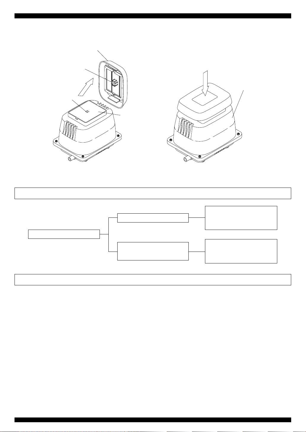
FILTER CLEANING AND REPLACEMENT
!CAUTION
To replace repair parts, proceed as follows: Be sure to use our designated genuine parts.
(1) When performing cleaning and/or replacement work, be sure to unplug the pump unit first.
(2) To remove the filter cover, put your fingers on one side of the cover and pull it up. (See Fig. 1.)
(3) Remove the filter from the upper housing, replace it with a new one or clean it. At this time, remove
any dust or foreign matter from the inlet of the filter cover, and the filter mounting surface and the
inlet of the filter. (The inlet is on the top of the upper housing and can be viewed when the filter is
removed.) If the filter is dirty, dust it off well. However, if it is heavily soiled, use a neutral detergent
to wash it down, rinse it well with water, and dry it out of the sun before reinstalling.
• When performing replacement work, the pump body may be still hot. Therefore, take care not to get
burnt.
• Clean the filter every three months. Clogged filters may result in abnormal heat generation or a
failure of the pump.
• Any dust or foreign matter attached on the pump inlet may cause abnormal noises or pump failure.
(4) Replace the filter, put the filter cover back on the upper housing as shown in the figure below,
align the fitting boss of the upper housing with its counterpart of the filter cover, then press the filter
cover downwards from above to fit it in. (See Fig. 2.)
• Take care not to press the filter cover in its improper position as it may be damaged.
• This pump is of a totally oil-less type. Therefore, never put oil or other liquids into the pump inlet.
6
Block Configuration
Chamber block
Diaphragm base
Diaphragm
Diaphragm ring
Casing
Valve
Valve chamber cover
Casing block
Diaphragm
mounting block
REPLACING THE CHAMBER BLOCKS
!CAUTION
• When performing the replacement work, the pump body may be still hot and you may get burnt.
So, wait until the pump has been allowed to cool.
• Replace the diaphragms and the valves with new ones once a year in order to maintain their initial
performance.
• For chamber block replacement, be sure to change both chamber blocks at the same time because
replacing only one of the two may cause a significant difference in life between the right- and left-
hand rubbers, making it impossible to maintain the performance of the pump.
• The rod employs powerful permanent magnets, and therefore be sure to remove your watch before
starting the work as it may fail due to their strong magnetic force.
• Do not put the rod close to a magnetic card, a magnetic disk or any other magnetic media as their
data may be lost.
Filter cover
Fitting boss
Fitting boss
Filter
Upper housing
Fig. 1 Fig. 2

7
(1) Prior to starting the work, be sure to unplug the pump.
(2) Remove all screws from the four corners, and the upper housing. If it is difficult to remove it due
tothe heavily stuck internal seal packing, pry it open by inserting the tip of a screwdriver into the
clearance between the exhaust nozzle and the upper housing .
(Figs. 3 and 4)
(3) Remove the sound absorber, hold the hose band and remove the L-tube from the casing nozzle.
Then, loosen the installation screws of the casing block for removal of the latter. (Figs. 5 and 6)
Screw
Screwdriver
inserting
position
Upper housing
Sound absorber
Fig. 3 Fig. 4
Sound absorber Hose band
L-tube
Screw
Casing Block
Fig. 5 Fig. 6
8
(4) Loosen the U-lock nut and remove one of diaphragm mounting blocks from the rod, and pull out
the other diaphragm mounting block from the pump body together with the rod without loosening
its U-lock nut. (Figs. 7 and 8)
!CAUTION
• Since we use powerful permanent magnets for the rod, take care not to get your fingers pinched
by unexpectedly being attracted with its force.
• When pulling out the rod, take care not to allow the rod projection to accidentally to hit the lever of
the automatic stop switch, as this may result in the safety screw of the switch damaging or in its
malfunction.
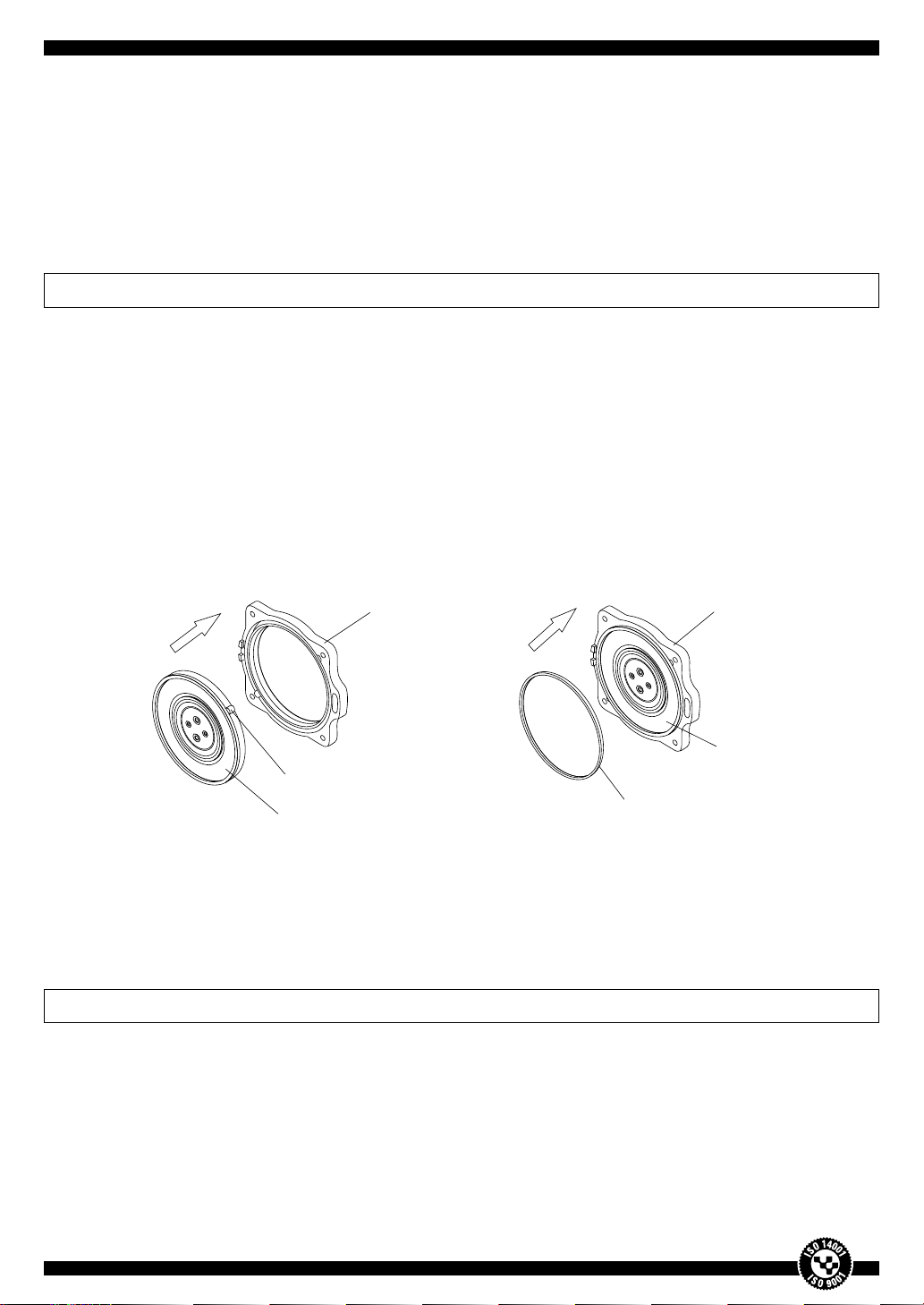
(5) To replace the diaphragm of the removed diaphragm mounting block, with a new one, first
remove the diaphragm ring from the diaphragm, then the diaphragm from the diaphragm base.
The ring and the diaphragm can be easily removed by hand, and if it is difficult to do so, then
hold them using radio pliers or the like, and pull them out one by one. (Figs. 9 and 10)
Diaphragm ring
Diaphragm
Diaphragm base
Diaphragm
Diaphragm base
Fig. 9 Fig. 10
9
(6) To reinstall the diaphragm, first fit a new diaphragm in the diaphragm base groove while aligning
the two diaphragm projections with their counterparts of the diaphragm base. Then, replace the
diaphragm ring in the diaphragm thus fitted. At this time, this diaphragm ring must be a new one
supplied with the replacement diaphragm. (Figs. 11 and 12.)
This completes the diaphragm replacement procedure, and use this assembly as a new
diaphragm mounting block.
!CAUTION
• At the time of changing diaphragms, be sure to replace the diaphragm rings also with the supplied
new ones. Since the old diaphragm rings may be likely to break, you may get injured when attemp-
tingto refit them for reuse.
• Be sure to fit the diaphragm ring as pump performance and life will be greatly affected, possibly
resulting in a failure.
(7) Install a new diaphragm mounting block on one side of the rod, insert the rod in accordance with
the procedure reverse to that performed when the rod was removed from the pump.
(Figs. 13 and 14)
!CAUTION
• Do not use removed U-lock nut and washer again as they may be loosened, which causes failure
of the pump. Therefore, use new U-lock nut and washer every time for replacing diaphragms
without fail.
Fig. 11 Fig. 12
Diaphragm
Diaphragm ring
Diaphragm base Diaphragm base
Diaphragm
Projection

10
!CAUTION
• Take care not to install the rod with iron particles, screws and other metallic substances attached
on the permanent magnets. Failure to do so can result in damage to the permanent magnets and/
or the electromagnets, or even in a failure of the pump.
(8) After the new diaphragm mounting blocks have been installed, install new casing blocks. The
casing blocks can be used again as new if the valves are replaced with new ones. To replace the
valves of the removed casing block with new ones, undo the five screws of casing A (Exhaust
part side) to remove casing B (Air valve side) and valve chamber cover. (Figs. 15 and 16)
(9) Pull out four old valves from the casing A using radio pliers, insert each new valve into the center
hole of valve seat while paying attention to the intake and exhaust sides, and pull these valves for
firm fitting, using radio pliers or other similar means. (Figs. 17 and 18)
Fig. 15 Fig. 16
Screw
Casing Block
Casing A
Casing B
Valve chamber packing

11
!CAUTION
• When replacing the diaphragms, be sure to change the valves with new ones, too.
• When reinstalling the valves, take care to make sure that they are correctly fit in the exhaust and
intake sides. Wrong orientation may result not only in performance decreasing but in a failure of
the pump.
• Tighten each of five screws gradually and uniformly till they are firmly fastened.
If they are not tightened uniformly, it may cause leakage of air or failure of pump.
(10) After the valves have been inserted into the casing A, cut off their respective pulling ends using
scissors or nippers. Secure casing B and valve chamber packing to casing A by the five screws.
(Fig. 19 and 20)
This completes the valve replacement procedure, and use this assembly as a new casing block.
Fig. 17 Fig. 18
Casing A
Valve
Exhaust side
Intake side
Fig. 19 Fig. 20
Cut section
Cut section

12
!CAUTION
(11) After the diaphragm mounting blocks have been installed, fix the new casing blocks by tightening
the four screws evenly in the reverse order to that done for disassembling, fit the L-tube in the
casing nozzle, and fix it firmly using the hose band. (Figs.21 and 22).
(12) When all the reassembly work has been completed, check the rod for no contact with the
electromagnet(s) or the screws for tightness.
(13) As a final step, put the frame cover back on the frame, tighten the four screws uniformly, then
cover the frame with the sound absorber. Furthermore, do not forget to put the frame cover on,
tighten each of four screws gradually and uniformly until they are firmly fastened.
(Figs. 23 and 24)
• Tightening a single screw too tight will make it difficult to tighten the remaining screws firmly, result-
ingin damage to the screws if forcibly tightened. Therefore, fasten all the four screws uniformly.
Fig. 21 Fig. 22
Screw
Hose band
Fig. 23 Fig. 24
Screw
Sound absorber

13
pin
SAFETY AUTOMATIC STOP SWITCH (SP SWITCH)
!CAUTION
1. Structure
The switch is installed in frame, and trouble defection lever is installed on top part of rod.
When diaphragms work properly, the movement of the rod between right and left is always
constant. However, if the diaphragms become damaged, pump works in the incorrect way.
As the result, the rod would be bias or over-moving. In this case, the top of the rod touches
the L-shaped lever and breaks the resin pin, which anchors L-shaped lever and the electrode.
That makes the constant point of the switching off and the pump turns off automatically. This
method lessens further pump damage by diaphragms break.
2. How to replace
If consumable spare parts, such as diaphragms are damaged, automatic stop switch works and
the movement of pump stops. At that time, please replace both the safety pin and diaphragms.
Procedure
(1) When you work with pumps, please never fail to pull off the electricity plug before working
on them.
(2) Referring to Fig.25, please penetrate safety pin through the electrode, L-shaped lever and
beam in such order.
(3) After replacing safety pins, please tighten safety pin and insert locking collar from beam side.
In case the locking collar is set on the proper point, please push that collar into the point.
(4) Then the setting of the switch is completed. (Fig. 26)
●Please never fail to pull off the electricity plug before working on them. If the pump remains con-
nected to the electricity supply, moving parts may cause injury or there is a possibility of electric
shock.
●Please remove broken safety pin and broken locking collar after replacing. Otherwise it causes
electromagnet damaged or causes pump broken.
●Please never fail to replace new locking collar for the maintenance purpose. Once you have
used locking collar, please do not reuse the same one as that collar does not function.
●Please replace safety pin after replacement of consumable spare parts. If you change safety
pin first, safety pin would be damaged when you insert the rod.
14
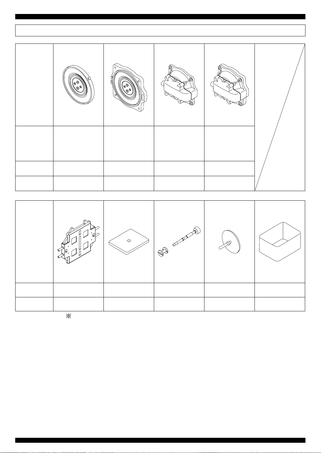
REPAIR PARTS
Furthermore, when you have lost or damaged the instruction manual, please contact us and we
will send you a copy at your cost. For inquires, please also contact our International Sales
Department.
Parts Name Diaphragm Block
2 pcs./set
Diaphragm
Mounting Block
2 pcs./set
Casing Block
2 pcs./set
Chamber Block
2 pcs./set
Consisting
of
• Diaphragm
• Diaphragm ring
• Diaphragm base
• Diaphragm
• Diaphragm ring
• Casing A
• Casing B
• Valve
• Valve chamber
packing
• Diaphragm
mounting block
• Casing block
Applicable
Models HP-150 & HP-200 HP-150 & HP-200 HP-150 & HP-200 HP-150 & HP-200
Order code 200DF00020 200PD00010 200PK00010 200PC00010
Parts Name Rod Filter Safety pin
for SP Switch
Valve Sound Absorber
Applicable
Models HP-150 & HP-200 HP-150 & HP-200 HP-150 & HP-200 HP-150 & HP-200 HP-150 & HP-200
Order code 200PR00300 120PA20010 PASPSW0400 200VV00010 QN09000100
When ordering parts, please specify the parts names and the corresponding order codes.

15
256 200
140 110
220
37
20
18
GENERAL VIEW AND DIMENSIONS
SPECIFICATIONS
(Unit : mm)
Specifications and design of these products are subject to change without notice for improvement.
Model HP –150 HP–200
Rated voltage V AC100/120/220~240V
Power supply frequency Hz 50 60 50 60
Normal operating pressure kPa 20.0
* Exhaust air flow rate l/min 150 160 200 210
* Power consumption W 125 155 210 250
* Noise level dBA (1m) 47 50
Weight kg 9.0
Denotes typical values and not those guaranteed.

INTERNATIONAL APPROVAL STANDARD CERTIFICATE OBTAINED
AN ENTERPRISE AIMING ENDLESSLY AT ENHANCING QUALITY
TECHNO TAKATSUKI CO., LTD.
What is ISO14001 & 9001?
ISO (International Organization for Standardization) 14001 Environmental Management
Systems are intended to provide organizations including companies with the elements of
an effective and voluntary environmental management system which can be integrated
with other management requirements, to assist organizations to achieve environmental
goals. And the ISO-14001 is called as “The enviromental passport” in internationally approved
standards. On the other hand, the ISO-9000 was established by ISO in 1987.These inter-
nationally approved standards provide specifications not for products but for quality-assur-
ance systems. ISO 9000 consists of three separate standards: ISO 9001, 9002, and 9003.
Of these, ISO 9001 is the most rigorous, encompassing points ranging from design con-
trol to after-sales service. To qualify for an ISO 9001 certificate, applicants must first pass
in-company, customer, and third-party audits. After receiving ISO 9001 certification, regular
checks are then conducted to ensure that the company maintains the required standards.
In addition, management policies on product quality are documented and checked against
actual practice throughout the entire organization. In essence, the ISO 9001 standard certi-
fies that a company has not only established an outstanding quality-control record, but has
also proven capable of sustaining this record.
The Product Liability Law
Japan’s Product Liability Law was introduced in July 1995 in response to the increasing
difficulty consumers were having in evaluating the quality of high-technology products
and in claiming damages associated with product defects. With the Product Liability Law
making it easier for customers to claim damages, manufacturers must now assign a higher
priority to quality control.
At Techno Takatsuki Co., Ltd., our response to the above developments was to create a
program that ensured our products were in compliance with the Product Liability Law. At
the same time, we implemented a full range of safety measures. As a results of these
efforts, we received ISO9001 certification in December 1995, a testament to the high
quality of our product design and manufacturing systems. Despite this initial success, we
remain determined to further improve our quality-control system, and look forward to the
support of our customers as Techno Takatsuki continues to evolve in years to come.
(All rights reserved)
HEAD OFFICE
8−16 HATCHO-NISHIMACHI, TAKATSUKI, OSAKA, JAPAN 569−0095
TEL : +81-726-84-0805 FAX : +81-726-84-0807
04.09.3000M
Printed in Japan KA20002010
PHILIPPINE TECHNO TAKATSUKI INC.
TOKYO BRANCH HINO FACTORY
This manual suits for next models
1
Table of contents
Other HIBLOW Water Pump manuals

Popular Water Pump manuals by other brands

IN-ECO
IN-ECO LR 060-H06 operating instructions

Little Giant
Little Giant CMD-100-3B owner's manual

Ecoplus
Ecoplus 727184 Instruction for installation and maintenance

Little Giant
Little Giant 15SC-CIA-RF owner's manual

Flofab
Flofab 8FFSEHA Series Installation, operation & maintenance manual

WaterAce
WaterAce R100U owner's manual


red lion
red lion Engine-Driven Aluminum TRANSFER Pump manual

FLORABEST
FLORABEST FTP 400 C2 translation of original operation manual

FLORABEST
FLORABEST FGPS 1100 B2 translation of original operation manual

Alfalaval
Alfalaval LKHP instruction manual

Little Giant
Little Giant GP-M231 manual

Aqua PRO
Aqua PRO AP4800 instructions