7. TROUBLESHOOTING
(A) PROBLEM: Unit will not start when the air valve is open and
the blue button has been pressed.
(A1) Cause: The operation of the button will normally be
and solution: accompanied by an audible ‘click’. If this sound is
not heard and there is no liquid in the reservoir turn
the unit upside down and try again. Otherwise incline
the unit to 45° and shake it several times then try
again.
(A2) Cause: The unit may require internal lubrication. Disconnect
and solution: the quick coupling. Open the air valve. Introduce a
few drops of air tool oil into the male coupling and
close the air valve. Reconnect the quick coupling.
When the unit is next operated the oil will be
distributed internally.
(B) PROBLEM: Automatic shut off does not operate when the
tank is full.
(B1) Cause: Turn air off manually and empty tank.
and solution: Take action as described in A1 and A2.
(C) PROBLEM: Extractor is working but no fluid is being
extracted.
(C1) Cause: All fluid has been extracted but tank is not full.
and solution: Turn off air manually.
(C2) Cause: Extractor probe is not fully immersed in the fluid.
and solution: Push extractor probe further into liquid/engine sump.
(C3) Cause: Tank is full.
and solution: Empty tank.
Dispose of waste liquids in accordance with local authority
regulations.
Always read and comply with the warnings on the brake fluid
container.
Wear eye protection and keep skin contact to a minimum. If brake
fluid enters eyes rinse with plenty of water and seek medical
advice. If swallowed seek medical advice immediately.
WARNING!Brake fluid is flammable - keep away from sources of
ignition, including hot surfaces e.g. exhaust manifold.
WARNING!Brake fluid will damage paintwork. Any spillage should
be flushed with water immediately.
8. BRAKE BLEEDING SAFETY
9. BRAKE BLEEDING OPERATION
fig.12 fig.13
fig.11
BRAKE BLEEDING PROCEDURE. Do not touch the
vehicle’s brake pedal whilst bleeding the brakes.
Refer to the vehicle manufacturer’s instructions for brake
bleeding and wheel sequence before proceeding. If no specific
instructions from the vehicle manufacturer exist, follow the
instructions detailed below.
WARNING! Familiarise yourself with the hazards of brake
fluid - read manufacturer’s instructions on the container.
9.1. Remove the lid of the vehicle’s brake fluid reservoir. Fill the
reservoir to its maximum mark.
9.2. Identify the brake bleeding tube which has a blue flexible
plastic brake nipple connector at one end and a black rubber
adaptor at the other.
9.3. Connect the brake bleeding tube to the top of the fluid
extractor’s tank by pushing the black rubber adaptor into the
fluid inlet coupling.
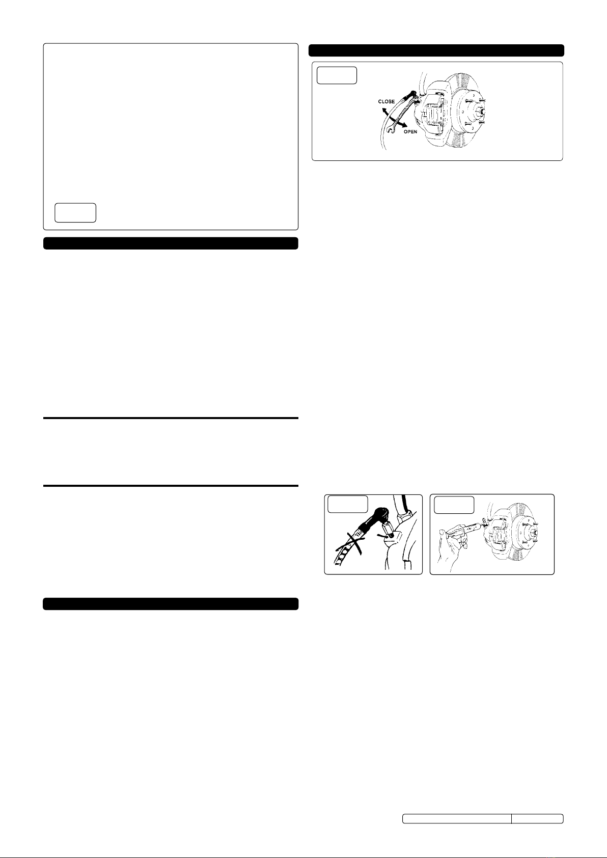
9.4. Push the blue flexible plastic brake nipple connector onto the
brake nipple on the first wheel and open the nipple about 1/4
of a turn. (See fig.11)
9.5. Turn on the air valve on the extractor (TP6903.V2 &
TP6904.V2). Press the blue button to activate air operated
units or operate the pump handle on manual models. A
vacuum will be created which will draw the brake fluid from
the vehicle’s brake system. Operate the unit for a few seconds
only to avoid draining the vehicle’s brake fluid reservoir entirely.
9.6. IMPORTANT: Check the level of brake fluid in the vehicle’s
reservoir and top up regularly. If possible a reservoir top
up device should be fitted to the brake fluid reservoir.
9.7. Continue to bleed the system and top up the reservoir until
there are no air bubbles visible in the clear tube (See fig.12).
9.8. Close the brake nipple (See fig.11).
9.9. Remove the rubber pipe from the brake nipple.
9.10. Repeat the process at each wheel in turn.
9.11. Changing the brake fluid
9.11.1. Repeat the brake bleeding procedure as described above
until the master cylinder reservoir is at its minimum level. Fill
the reservoir with new brake fluid and continue to bleed the
system. Check reservoir level regularly.
9.11.2. When new fluid can be seen in the clear tube tighten the
brake nipple.
9.11.3. Repeat this procedure at every wheel.
When brake bleeding and/or fluid changing is complete,
test action of brake pedal to ensure that the brakes are
working before driving the vehicle.
9.11.4. Apply copper grease to the brake bleed nipples before and
after the brake bleeding procedure to eliminate the possibility
of seized or broken nipples when the brakes are next bled
(See fig.13).
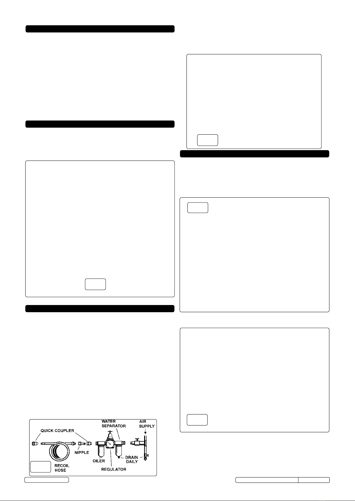
fig. 10
NOTE: It is our policy to improve products continually and as such we reserve the right to alter data, specifications and component parts without prior notice.
IMPORTANT: No liability is accepted for incorrect use of this product.
WARRANTY: Guarantee is 12 months from purchase date, proof of which will be required for any claim.
INFORMATION: For a copy of our latest catalogue and promotions call us on 01284 757525 and leave your full name and address, including postcode.
TP6901.V2, TP6903.V2, TP6904.V2 Issue: 1-28/01/13