RS Mini Galaxy E 050-600 User manual

CO
2
Incubator
Model No: 050-600
User Manual

1
Issue E, January 2009
Contents
ContentsContents
Contents
Section Page No
1. Product Description 2
2. Guidance Notes and Routine Checks 3
3. Installation 4
4. Setting the Hu idity Conditions 7
5. Control Panel Description 8
6. Progra ing Te perature, CO2
& Auto Zeroing 9
7. Progra ing the Alar Syste 10
8. The Alar Syste 11
9. Syste Alar s 13
10. Cleaning and Disinfecting 14
11. Technical Specification 15
12. Ordering Infor ation 16
13. Accessories 18
If this incubator is fitted with Model Options, User Instructions and infor ation is located at the back,
after Ordering Infor ation.

2
Section 1
Section 1Section 1
Section 1
Product Description
The MiniGala y E CO
2
Incubator is designed to ensure accurate and reliable operation. The unit
incorporates a touch sensitive keypad and two, 3 digit L. E. D. displays which allows easy setting and
onitoring of the cha ber condition.
The icroprocessor control syste ensures a rapid, controlled return to opti u cha ber conditions
after a door opening whilst also preventing any overshoot.
A ther al heating ele ent co pletely surrounds the incubator providing an even te perature within
the cha ber. The independently heated outer door is designed to ensure an even distribution of heat
thereby eli inating condensation on the inner door.
Incorporated into the unit is an over te perature safety syste . This operates independently of the
ain control syste .
A purpose designed hu idity control syste allows a high unifor relative hu idity and prevents
undesirable condensation in other parts of the cha ber. The anual control syste allows li ited
adjust ent over an approxi ate range of 95 – 97% r/h.
A solid state infra red sensor is used to control the level of CO
2
giving excellent reliability and is
unaffected by hu idity. The CO
2
syste has a se i-auto atic zero function which provides a si ple
process for the user to follow to aintain the correct CO
2
level within the cha ber.
There is a two level alar syste . The cha ber onitoring alar is progra able and will alert you
if te perature or CO
2
have not recovered within a preset ti e after the door has been opened. If not
required, this syste can be disar ed. Syste alar s occur only if a fault has developed which
requires user intervention to rectify.
Air circulation is achieved without the use of a fan eli inating this potential source of conta ination
and reducing s all sa ple evaporation within the cha ber.
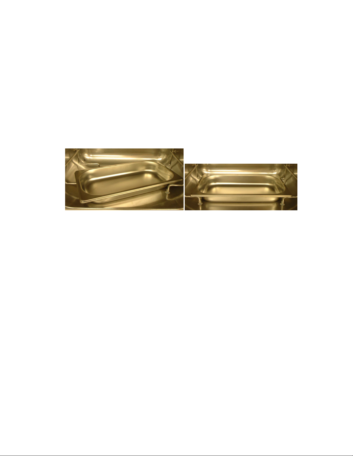
The 50 litre cha ber and all internal co ponents are anufactured fro polished stainless steel.
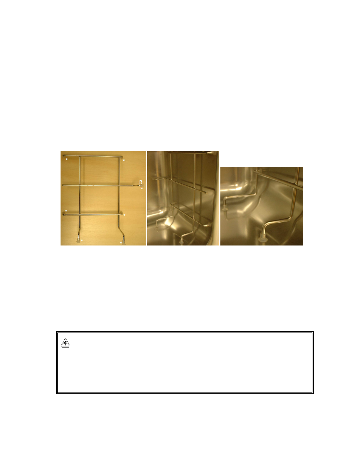
The shelf rack syste is designed for co plete re oval and easy access to the s ooth interior for
quick and thorough cleaning.
The outer shell of the incubator is anufactured fro zinc plated stove ena elled steel to give a
durable corrosion resistant finish.
The outer door and top cover are vacuu for ed fro ABS plastic and they provide a high level of
insulation. The keypad and display are incorporated into the top cover per itting axi u usable
cha ber volu e.

3
Section 2
Section 2Section 2
Section 2
Guidance Notes and Routine Checks
2.1 To ensure that cha ber conditions re ain as stable as possible always ini ize the length
of ti e that the inner door is open. The agnetic door catch is specifically designed to ake door
opening and closing as easy as possible. When opening the inner door, wipe off any s all drops of
condensate that ay have for ed on the inner seal. This will avoid a build up of condensation.
2.2 For cell culture work – we reco end the use of copper sulphate (or recognised biocide) in
the hu idity tray. Tests have shown that as well as inhibiting bacterial growth in the tray this
can reduce conta ination on the cha ber walls (one s all teaspoonful copper sulphate
reco ended).
2.3 For IVF and other sensitive work – we do not reco end the use of any biocide in the
hu idity tray. To reduce the possibility of conta ination, the hu idity tray water should be
changed and the hu idity tray cleaned with 70% Alcohol / 30% distilled water solution every
10 – 14 days. To re ove / replace the hu idity tray: - turn the tray through 45° and re ove
for refilling. To replace the hu idity tray, carefully turn through 45° and pass the tray through
the front of the shelf racks.
2.4
Daily
2.4.1 Check that the te perature and CO
2
levels are reading within specification.
2.4.2 Check the reserve pressure in the CO
2
cylinder (nor ally 50 bar when full). The design of
the incubator ensures very low consu ption of CO
2
and during nor al working conditions a type K
cylinder should last approxi ately 12 onths. If there is a significant drop at the cylinder 50 bar
pressure, it eans that the cylinder is al ost e pty and should be replaced, ensuring that there are
no leaks at any of the joints.
2.5
Monthly
2.5.1 If not changing the hu idity tray water / cleaning hu idity tray regularly - top up the hu idity
tray (to a axi u volu e of 0.5 litres). The use of war water (approx. 37.0°C) will ensure a rapid
return to opti u cha ber conditions. After topping-up, check that the hu idity tray is central
between the racks and pushed back against the stops.

4
Section 3
Section 3Section 3
Section 3
Installation
3.1 Unpack the incubator by lifting it fro the delivery pallet ensuring it is supported by the base.
At least two people are required for safe lifting. In the unlikely event of any transit da age this
ust be reported within 7 days.
3.2 The following ite s are supplied with your new incubator:-
3 Non-tip shelves (securely packed separately)
2 shelving racks (securely packed separately)
18 Silicone Rubber Suction Feet. Supplied packed in accessory bag
1 Hu idity tray (securely packed separately)
1 Mains power cord supplied packed in accessory bag
3 of PVC 6 bore plastic tubing supplied in accessory bag
1 CO
2
HEPA-vent filter (connected to PVC tube in accessory bag)
2 Hose clips supplied packed in accessory bag
4 Adjustable feet (To ensure adequate airflow for correct operation of the relative hu idity
control syste the incubator feet must be fitted. Feet are supplied fitted to the unit.
4 Anti-slip pads for the adjustable feet
1 Black sensor cover (in situ)
If required, further shelves can be purchased up to a axi u of 6. The hu idity tray has a fixed
position at the lowest shelf rack position. The hu idity tray should always be left in place even if the
incubator is not hu idified.
3.3 In order to use the incubator you will require:-
a) A 220/240V 50 Hz or 100/120V 50/60 Hz earthed electrical supply - ini u
capacity 3 a ps (5 a ps High Te perature Deconta ination Models).
Or
A 100/120V 50/60 Hz earthed electrical supply - ini u capacity 6 a ps (8
a ps High Te perature Deconta ination Models).
b) CO
2
gas cylinder (100% CO
2
vapour withdrawal) together with a two
stage regulator for pressure control to 0.35 BAR. (5lbf / in
2
).
c) Copper Sulphate or other biocide for the hu idity reservoir (optional).
3.4 The incubator is designed to operate at a cha ber te perature of 4.0°C above a bient and
at an absolute ini u a bient te perature of 15°C if being used at 37°C. Therefore care
should be taken to avoid placing the incubator in draughts, direct sunlight or near a radiator.

5
The operating temperature range indicated above excludes any heat generating
equipment operating within the unit. The presence on any such appliance will affect the
operational temperature characteristics.
3.5 To ensure adequate airflow for correct operation of the relative hu idity control syste the
incubator feet must be fitted to insert the adjustable feet, front pair first, tilt the incubator
backwards, screw the feet in to the required depth. Repeat the operation, tilting the incubator
forward for the rear pair.
3.6 Place the incubator in the working position. The unit is designed to be sited on a level surface
capable of bearing 32kg (approx – actual weight will depend on options fitted). It is
reco ended that a spirit level be used on the centre of the iddle shelf to position the
incubator, the feet can be individually adjusted to co pensate for uneven surfaces. Fit the
anti-slip pads to the front feet. Purpose designed stands and stacking asse blies are also
available.
3.7 Asse ble the shelf racks as follows:- Carefully re ove any packaging. Fit 7 silicone rubber
suction cup feet to the shelf racks in positions indicated on the picture below left with an ‘*’.
Repeat for the opposite shelf rack.
To fit the shelf racks to the incubator:- The racks are ‘handed’ and the suction cup arked ‘R’
goes to the rear of the cha ber as shown in the centre picture above. The suction cups will
adhere to the cha ber walls dry, but can be da pened with distilled water to increase
adhesion if required. Ensure the shelf racks are fitted squarely to the cha ber to enable the
shelves to sit on a level plane (picture above right).
3.8 Connect the CO
2
using the 6 plastic tubing to the atching CO
2
inlet on the rear of the
incubator. Use the tubing clips provided to eli inate CO
2
leaks. Turn on the gas supply with
the pressure set to 0.35 BAR (5lbf/ in2). Re ove the black protective cover fro sensor
(keep for use when disinfecting). Ensure that the white porous sensor cover re ains in place.
WARNING!
CO
2
levels.CO
2
is harmful in high concentrations. Any gases that may escape from the
unit have to be managed via adequate room ventilation or the use of an e haust system.
Check compliance with the ma imum permitted workplace concentration for CO
2
when
operating all units.

6
3.9 Connect the incubator to an earthed power supply using the power cord provided. The display
will illu inate i ediately. NB:- Do not progra e the CO
2
level yet
3.10 The cha ber set points are pre-progra ed at 37.0°C and 0% CO
2
. Leave the incubator
until the progra ed cha ber te perature has been reached.
3.11 Carefully unpack the hu idity tray. Fill with 0.5 litres of war distilled water (at approx.
37.0°C). For cell culture work – we reco end the use of copper sulphate (or recognised
biocide) in the hu idity tray (one s all teaspoonful copper sulphate reco ended).
For IVF and other sensitive work – we do not reco end the use of any biocide in the
hu idity tray. To reduce the possibility of conta ination, the hu idity tray water should be
changed and the hu idity tray cleaned with 70% Alcohol / 30% distilled water solution every
10 – 14 days. To re ove / replace the hu idity tray: - turn the tray through 45° and re ove
for refilling.. To fit the hu idity tray - Turn the hu idity tray through 45° and pull it forward as
shown in the pictures on the following page:-
NB – ensure that the Hu idity Tray is located centrally between the racks and pushed fully
back against the stop as shown above right.
3.13 Fit the shelves and leave the incubator for at least two hours (preferably overnight) to allow
conditions to stabilise.
3.14 Progra e the CO
2
level (i.e. 5%) and ensure that the CO
2
level stabilises at the
progra ed level
3.15 To carry out the Auto Zero, press the
‘∗’
and
‘↵’
keys si ultaneously. The Inner Door ust
be opened and closed according to the displayed instructions, after which the process is
co pletely auto atic.
3.16 The incubator is now ready for use.

7
Section 4
Section 4Section 4
Section 4
Setting the Humidity Conditions
If hu idification is required, the hu idity tray which is located on the lower shelf runners
should be pulled forward and filled with 0.5 litres of war distilled water for cell culture work –
we reco end the use of copper sulphate (or recognised biocide) in the hu idity tray. Tests
have shown that as well as inhibiting bacterial growth in the tray this can reduce
conta ination on the cha ber walls (one s all teaspoonful copper sulphate reco ended).
For IVF and other sensitive work – we do not reco end the use of any biocide in the
hu idity tray. To reduce the possibility of conta ination, the hu idity tray water should be
changed and the hu idity tray cleaned with 70% Alcohol / 30% distilled water solution every
10 – 14 days. To re ove / replace the hu idity tray: - turn the tray through 45° and re ove
for refilling.
DO NOT LEAVE WATER IN THE HUMIDITY TRAY IF THE INCUBATOR IS SWITCHED OFF , AS
THIS MAY RESULT IN DAMAGE TO THE CO
2
SENSOR.

8
Section 5
Section 5Section 5
Section 5
Control Panel escription
Control Panel escriptionControl Panel escription
Control Panel escription
The control panel consists of two, 3 seg ent LED displays, and 4 keys. The functions and
descriptions of these are described below.
∗
PROGRAMMING Key
+
PLUS Key
-
MINUS Key
‘↵’
ACCEPT Key
The deci al points on the display for Te perature and CO
2
flash ON / OFF to signify that the Alar
Syste is not ar ed.
The picture above shows the screen in nor al operation, this is how the screen should be illu inated
when running nor ally.

9
Section 6
Section 6Section 6
Section 6
Programming Temperature, CO
Programming Temperature, COProgramming Temperature, CO
Programming Temperature, CO
2
2 2
2
& Auto Zeroing
& Auto Zeroing& Auto Zeroing
& Auto Zeroing
6.1 Programming Temperature & CO
6.1 Programming Temperature & CO6.1 Programming Temperature & CO
6.1 Programming Temperature & CO
2
22
2
The
‘∗’
Key allows Te perature and CO
2
to be progra ed within the following ranges:
Te perature Range: 10°C ( ust be 1°C above a bient) to 50°C.
CO
2
Range: 0.2% to 10%
Once the Te perature has been progra ed it ust be entered with the
‘↵’
Key, the CO
2
can then
be progra ed.
Press the
‘+
’ and
‘-’
keys si ultaneously to enter the Engineering Mode. If this is inadvertently done,
press the
‘∗’
key to exit.
6.2 CO
6.2 CO6.2 CO
6.2 CO
2
2 2
2
Auto Zero
Auto ZeroAuto Zero
Auto Zero
The purpose of the Auto Zero syste is to reference the CO
2
Sensor to an at ospheric CO
2
level of
0.05%. Over a period of ti e the sensor zero ay drift causing an inaccuracy in the CO
2
level at the
progra ed value. It is reco ended that the CO
2
syste is Auto Zeroed onthly to ensure that
CO
2
level is correct.
To carry out the Auto Zero, press the
‘∗’
and
‘↵’
keys si ultaneously. The inner door ust be
opened and closed according to the displayed instructions, after which the process is co pletely
auto atic.
6.2.1 The door is opened for 60 seconds to co pletely degas the cha ber. A countdown is shown
on the display after which the instruction to close the door is displayed.
6.2.2 The door is then closed and a 10 inute countdown starts, to allow the cha ber conditions to
recover and the CO
2
sensor signal to stabilise, after which the sensor signal is auto atically re-
referenced. If the door is accidentally opened during the 10 inute countdown, close the door again to
reset the ti er and resu e the Auto Zero process until co plete.
6.2.3 The incubator will now re-open the CO
2
valve to allow the CO
2
level to recover to the
Progra e value.
6.2.4 Pressing the ‘
∗
’ key will auto atically ter inate the Auto Zero. Pressing any other key or
opening the door during the Auto Zero will not ter inate it.

10
Section 7
Section 7Section 7
Section 7
Programming The Alarm System
Programming The Alarm SystemProgramming The Alarm System
Programming The Alarm System
Press the
‘↵’
&
‘-’
Keys si ultaneously to enter Alar Progra Mode.
7.1
Setting the High and Low Te perature Alar s.
The LED display shows
°
°°
°
C
CC
C
.
AL
ALAL
AL
. . Press the
‘↵’
Key to display the High Te perature Alar ,
HI 37
HI 37HI 37
HI 37.5
55
5
. The factory setting is the progra ed value +0.5°C. This value can be adjusted using the
‘+’
&
‘-’
Keys, the ini u setting is 0.5°C fro set point. Press the
‘↵’
Key to accept the setting
and the Low Te perature Alar is displayed
LO
LOLO
LO
36
3636
36
.
5
55
5
. Press the
‘↵’
Key to accept the setting.
7.2
Setting the
CO
2
High and Low Alar s.
Press the
‘+’
Key, the display will show
CO2
CO2CO2
CO2
.
AL
ALAL
AL
. . Press the
‘↵’
Key to display
HI
HIHI
HI
.
5
55
5
.
5
55
5
Adjust ent and the Low Alar Set point are as described in 1) above.
7.3
Door Open Alar .
To adjust the ti e delay after opening the door before the alar sounds, Press the
‘+’
Key, the
display will show
doo
doodoo
doo
.
rAL
rALrAL
rAL
Press the
‘↵’
Key and the
‘+’
&
‘-’
Keys to adjust the ti e in the
following steps – 15, 30, 45, 60, 75 & 90 seconds, then OFF. Press
‘↵’
to select the preferred value.
Press
‘∗’
to return to the Main Alar Progra ing Menu. Press
‘∗’
again to return to the ain
display.
7.4
Alar Duration.
To adjust the length of ti e which all Alar s are on for. Press the
‘+’
Key, the display shows
Per
PerPer
Per
.
Iod
IodIod
Iod
. Press the
‘↵’
Key and the
‘+’
&
‘-’
Keys to adjust the Alar on ti e in the following steps -
OFF, 10 sec, 30 sec, 60 sec, 600 sec, 1 Hr , then ON. Press
‘↵’
to select the preferred value.
Press
‘∗’
to return to the Main Alar Progra ing Menu. Press
‘∗’
again to return to the ain
display.
7.5
Alar Ar Ti e.
This is the length of ti e that is allowed for the Te perature and CO
2
to recover before the Alar
Syste is ar ed. Press the
‘+’
Key, the display will show
dr
dr dr
dr
.
dEL
dELdEL
dEL
Press the
‘↵’
Key and the
‘+’
&
‘-’
Keys to adjust the Alar Ar ti e in the following steps – 0.15 Hr (15 ins), 0.20, 0.30, 1.00,
then OFF. Press
‘↵’
to select the preferred value.
Press
‘∗’
to return to the Main Alar Progra ing Menu. Press
‘∗’
again to return to the ain
display.
NB – When set to OFF the Alar will ar only when progra ed set point is reached.

11
Section 8
Section 8Section 8
Section 8
The Alarm System
Refer to the Flow Chart on the following page.
8.1 At switch on or after the progra ed values have been reprogra ed, the Alar Syste is
inactive until the progra ed values ± 0.1 are achieved, after which the Alar Syste is
ar ed. If Te perature and / or CO
2
levels deviate ore than ± 0.5°C / % CO
2
, the display
flashes, the buzzer sounds and a essage appears on the screen. This can be cancelled by
pressing any key.
8.2 When the inner door is opened the Alar Syste is disabled and on closing the door the
preset Alar Ar ti eout starts. If cha ber conditions recover within the Alar Ar Ti e,
the Alar Syste is rear ed. At the ti eout the Alar Syste is ar ed and if the
Te perature and CO
2
are outside the ± 0.5 alar point, the alar will be activated.
8.3 If the alar is not acknowledged and cha ber conditions subsequently recover, the Audio
alar is cancelled but the alar essage is left on the screen to alert the user to the fact that
an alar has occurred. The essage can be cancelled by pressing any key.
8.4 The duration of the Audio Alar can be adjusted fro inactive to continuous. See
Progra ing the Alar Syste , Section 7.

12
Chamber Alarm System Flow Chart
15 INUTES
ALAR DELAY
TI EOUT
CO PLETED
ARE TE PERATURES AND CO2
LEVELS WITHIN +/- 0.1 OF SET
POINT?
CHANGE
PROGRA ED
VALUES
OPEN INNER DOOR
DISAR ALAR S
CLOSE INNER
DOOR
15 INUTES
ALAR DELAY
TI EOUT STARTED
IS TE PERATURE OR CO2 LEVEL
ORE THAN +/- 0.5 OUTSIDE
PROGRA ED POINTS?
CANCEL ALAR BY
PRESSING ANY KEY
ALAR S
CANCELLED
VISUAL AND AUDIBLE
ALAR S CANCELLED,
ESSAGE LEFT ON SCREEN
CANCEL
ESSAGE BY
PRESSING ANY
KEY
NO
YES
YES
SWITCH ON
AR ALAR S
VISIBLE AND AUDIBLE
ALAR - ESSAGE ON
SCREEN
HAVE CONDITIONS
RECOVERED TO
WITHIN +/- 0.1?
YES
NO
NO

13
Section 9
System Alarms
9.1
Te perature Sensor Alar s.
9.1.1 In the event of any one of the four te perature sensor failing (there are two in the door and
two for the cha ber), the following essage will appear
°
°°
°
C FAIL
C FAILC FAIL
C FAIL
Because the incubator can no longer control te perature properly the heating will switch off and the
incubator will cool down to roo te perature.
If a sensor fails but subsequently corrects itself, the te perature control will restart and an alar
essage as follows will be re ain on the te perature side of the display
SAL
SALSAL
SAL
...
This essage can be cancelled by pressing any key.
9.2 Over Te perature Cut-out / Alar .
9.2.1 This alar only occurs if the Cha ber te perature exceeds the progra ed te perature
by 1°C or if the ele ent exceeds Set Point + Cha ber Control Point Hi +1°C. The
activation threshold is fixed and cannot be adjusted.
9.2.2 Following activation, the over te perature cut-out / alar syste operates in 2 sequential
odes:-
Mode 1:- Over te perature cut-out / alar activates and cuts power to the heating
ele ents and the CO
2
control valve. The condition is shown on the display by the essage
°
°°
°
Ct
Ct Ct
Ct riP
riP riP
riP
. When the cha ber te perature has fallen to the progra ed set point, the
syste changes to ode 2.
Mode 2:- The control syste then tries to aintain the cha ber te perature at the
progra ed level by switching the heating ele ents on and off using an e ergency less
precise control ethod. The essage
tAL
tALtAL
tAL
. will flash on screen to signal that an over
te perature fault occurred and the incubator is being controlled by the e ergency control
syste . This essage cannot be cancelled fro the keypad.
9.2.3 Nor al te perature control can be regained and the over te perature cut out / alar
cancelled by reprogra ing the te perature, opening / closing the glass door, or switching
the incubator off / on. If the proble persists the alar will re occur, if this happens please
consult your distributor.
9.3
CO
2
Alar s.
9.3.1 This alar only occurs if the CO
2
Auto Zero cannot adjust to reference the signal to
at osphere at the end of the Auto Zero the following essage will appear
AUTO ZERO FAI LED
AUTO ZERO FAI LEDAUTO ZERO FAI LED
AUTO ZERO FAI LED
This eans that the CO
2
Sensor is defective and requires replace ent.
If any of these alar s occur then contact your distributor i ediately.

14
Section 10.
Section 10.Section 10.
Section 10.
Cleaning and Disinfecting
Cleaning
10.1 The exterior of the incubator should be kept clean by wiping over with a soft cloth and
soapy water.
Disinfecting
10.2 The reco ended disinfecting agent for use with the incubator is a solution of 70%
Isopropanol (alcohol) and 30% distilled water. Appropriate safety regulations should be
followed when using this solution. Gloves should be worn as a routine precaution. Alcohol
can for an explosive vapour in confined spaces – ensure adequate ventilation during
cleaning. There will be no adverse effects to the incubator if the following procedures are
carried out:-
10.3 Progra 0.0% CO
2
and switch off the incubator. Disconnect fro the ains supply.
10.4 Da pen a clean cloth with the 70 / 30% solution and wipe down all external surfaces. Take
care not to let any of the liquid co e into contact with any electrical outlets or asse blies.
10.5 Re ove all shelves, the hu idity reservoir, shelf runners, shelf racks and inner door seal.
10.6 Place the black protective cover over the CO
2
sensor, also protect any additional sensors
such as Oxygen or hu idity with the cover(s) supplied.
10.7 NOTE: It is very i portant to ensure that no disinfectant solution is spilled onto the white
porous CO
2
sensor cover at the rear of the cha ber. Failure to use the protective cover(s)
could result in da age to the sensor(s) and ay affect your warranty.
10.8 The hu idity reservoir can be cleaned by rinsing in sterile water, wiping down with the
alcohol solution, and rinsing with sterile water.
10.9 Wipe down the inside of the cha ber with alcohol / water solution, and leave to dry
co pletely.
10.10 Wipe the internal co ponents of the cha ber with alcohol / water solution twice. Wipe off
excess liquid and leave to dry co pletely. Re-asse ble in reverse order before switching
the incubator on. Wipe the inner door seal with the alcohol solution, rinse and leave to dry.
Ensure the protective cover(s) are re oved fro the sensor(s) and replaced in the holder
for safe keeping (protective covers ust also be re oved fro any additional sensors fitted
such as Oxygen or hu idity).
10.11 Refill the hu idity tray with 0.5 litres of war distilled water (approx. 37.0°C). For cell culture
work – we reco end the use of copper sulphate (or recognised biocide) in the hu idity
tray. (one s all teaspoonful copper sulphate reco ended).
For IVF and other sensitive work – we do not reco end the use of any biocide in
the hu idity tray. To reduce the possibility of conta ination, the hu idity tray water should
be changed and the hu idity tray cleaned with 70% Alcohol / 30% distilled water solution
every 10 to 14 days. NB – ensure that the Hu idity Tray is pushed fully back against the
stops.
10.12 Leave the incubator for at least two hours (preferably overnight) to allow conditions to
stabilise.
10.13 When the incubator has stabilised, carry out an Auto Zero and re-progra the desired CO
2
level.
10.14 Never use the following substances to clean the stainless steel as da age will result:
Sodium Azide, Aqua Regia, Iodine, Ferric hloride or Sulphuric Acid.

15
Section 11
Section 11Section 11
Section 11
MiniGalaxy E Technical Specification
MiniGalaxy E Technical SpecificationMiniGalaxy E Technical Specification
MiniGalaxy E Technical Specification
Temperature Management
Digital progra ing via icroprocessor control on 0.1°C incre ents. Measure ent of cha ber and
door te perature via 4 RT atched ther istors (sensitivity 0.01°C)
Adjustable independent control of door heater.
“Out of Li its” te perature protection syste independent of icroprocessor control.
Range: 4°C above a bient te perature to 50°C
Control: ± 0.1°C
Stability: ± 0.1°C
Unifor ity: ± 0.2°C
CO
2
Control
Solid state infra-red CO
2
sensor operating independent of hu idity. Progra able, fully auto atic
zeroing facility.
Range: 0.2 - 10%, or 0.2 - 20%
Control: ± 0.1%
Long Ter Stability: ± 0.2%
Unifor ity: ± 0.1%
Recovery Rate: Better than 0.7% inute
Gas Connections: 6 tubing
Required Gas Pressure: 0.35 bar / 5psi
Relative Humidity
Co pletely dry wall cha ber with re ovable stainless steel hu idity reservoir.
Reservoir Capacity: 0.5 litres
Hu idity Control: Nor al: 95% at 37°C
High: 97% at 37°C
Shelves
Polished stainless steel, non - perforated.
Usable Space (WxDxH): 350 x 250 x 100 per shelf (with 3 shelves)
Usable Area: 875c
2
per shelf
Standard No of Shelves: 3
Multiple Position Option: 2 to 6 shelves

16
Alarm Systems
Two-level alar syste giving progra able audio / visual warnings with options for re ote
co unication. Level 1 signals syste failures, level 2 is progra able and onitors cha ber
conditions.
Dimensions
Sea less fully radiused interior with re ovable door seal
Cha ber (HxWxD): 401 x 401 x 308
Cha ber Volu e: 48 litres
External (HxWxD): 645 x 484 x 470
Crated Di ensions (HxWxD): 790 x 620 x 610 (Including pallet)
Weight (uncrated): 32kg (approx – actual weight will depend on options fitted).
Weight (crated): 50kg
Electrical Supply
Earthed Electrical Supply of:
Voltage: 220 - 240v 50/60Hz
Or 100 - 120v 50/60Hz
Power: 500 watts
Energy to aintain 37°C: < 0.1kwh.
Storage Temperature
10 - 50°C
NB:-
Factory calibration of the incubator is carried out at 37°C, 5% CO2 & 95% RH in an a bient
te perature of 20 - 25°C, with no heat-generating apparatus inside the cha ber.
Software calibration adjust ents ay be required to opti ise perfor ance if the incubator is being
used well outside of these operating conditions. Perfor ance specifications ay also be affected.
Please contact RS Biotech, quoting the incubator Serial Nu ber and co plete details of operating
conditions, for advice on calibration adjust ents and relevant perfor ance specifications.

17
Section 12
Section 12Section 12
Section 12
Ordering Information
Ordering InformationOrdering Information
Ordering Information
MiniGalax
MiniGalaxMiniGalax
MiniGalaxy E
y Ey E
y E
Add option nu bers to the base nu bers.
Galaxy E Incubator: 0.2% - 10% CO
2
220 / 240V 50 / 60 Hz Model: 050 – 600
100 / 120V 50 / 60 Hz Model: 050 - 601
No Charge (Factory Fitted) Options:-
CO
2
Control 0.2 - 20%* 050 – 513
Left Hand Door (hinged on right) 050 - 527
Model Options:-
Access Port (∅10 ) 050 – 019
RS232 Port 050 - 020R*
Split Inner Door 050 – 022
BMS Relay Contact Alar * 050 - 023*
*Can be retrofitted by Service Person
So e option co binations are not possible, others ay incur extra cost. Please enquire before
ordering.

18
Section 13
Section 13Section 13
Section 13
Accessories
Perforated Shelves 050 – 104
Non - Perforated Shelves 050 – 105
Floor Stand, 400 height for double stacking 050 – 116
Galaxy Log V1.0 PC-based data-
collection software & RS232 Port 050 – 117
Stacking Fra e for double stacking 050 – 118
Multi-position Shelf Racks (Max 6 positions) 050 – 121
Auto atic CO
2
Cylinder Change over Unit 170 – 101
CO
2
Two-stage Regulator 170 – 102
CO
2
Filter (supplied in pairs) 170 – 103
In-line Pressure Regulator 170 – 110
CO
2
Gas Analyser co plete with 10 Testing Tubes 170 – 113
10 Spare Gas Analyser Testing Tubes 170 – 114
Air Zero Filters (supplied in pairs) 170 – 115
Table of contents
Other RS Accessories manuals
Popular Accessories manuals by other brands

Panasonic
Panasonic MA27P11 Specification sheet

La Crosse Technology
La Crosse Technology BREEZE PRO SENSOR manual

Honeywell Home
Honeywell Home DW915 Series manual

SunSetter
SunSetter VISTA Owner's manual and installation instructions

Elsys
Elsys ERS2 Series ERS2 Lite operating manual

Steinberg
Steinberg UR28M Operation manual