RSF Energy OPEL 2000 User manual

OPEL 2000 1
Keep these instructions for future use.
The
Owner's
Manual
Residential
Factory Built
Fireplace
Operation
Maintenance
Installation
OPEL 2000
opel8/99
manual

OPEL 2000 2
Dear Customer,
The OPEL 2000 incorporates technology with elegance to give you a beautiful view of the fire without compromising
on heating efficiency or environmental quality.
We have designed your new OPEL 2000 to be easy to install, operate and maintain. It is in your best interest to
become familiar with it. Study your manual to be sure that the installation is correct, then follow the guidelines for
operation and maintenance.
We at RSF ENERGY congratulate you on your choice of the OPEL 2000, and are confident that you have
purchased a fireplace that is simply, the best.
Sincerely,
The RSF Energy Team,
June, 1999
SAFETY FIRST
3 Dos and Donts
3 Creosote Formation and Need for Removal
GENERALSPECIFICATIONS
3 Combustion Control System
4 Firescreen
4 Thermostat
4 Internal Circulating Blower
4 Gravity Vent System
4 Central Heat System
4 Catalytic Combustor
OPERATION
5 Lighting
5 First Fire
5 Refueling
MAINTENANCE
6 Cleaning
6 Disposal of Ashes
6 Doors
7 Glass
7 Gold Plating
8 Chimney Cleaning
8 Paint
8 Catalytic Combustor
INSTALLATION
9 General Assembly Illustration
10 Nailing Strips
10 Location
10 Ceiling Clearance
10 Outside Air Duct
12 Chimney
12 Chimney Installation
12 Masonry Chimney
14 Chase Enclosure
14 Radiation Shield
15 Offset Chimney
15 Framing In
16 Spark Guard
16 Mantel
16 Hearth Extension
16 Micore Board
OPTIONS
19 Wall Thermostat
20 Circulating Blower
21 Catalytic Combustor
23 Gold Louvers
25 Rock Retainer Kit
26 Remote Venting
26 The Gravity Vent System
27 The Central Heat System
32 Zone Heating
SCHEMATIC WIRING DIAGRAMS
34 Thermostat
34 Circulating Blower
35 Central Heat System
35 All Systems
36 Zone Heating
REPLACEMENTPARTS
37 Replacement Parts
FIREPLACE OPTIONS
38 Fireplace Options
WARRANTY
39 Warranty
TABLE OF CONTENTS

OPEL 2000 3
SAFETY FIRST
DOS AND DONTS
If this fireplace is not properly installed, a house fire
may result. For your safety, follow the installation
directions. Contact local building or fire officials
about restrictions and installation requirements in
your area.
Note: We strongly recommend installers to be WETT
or WHERF certified.
To ANYONE using this fireplace:
These DOs and DO NOTs are for your safety.
1. DO read this instruction manual before lighting your
first fire.
2. DO burn seasoned wood fuel or processed solid fuel
firelogs.
3. To avoid glass breakage, DO NOT slam the fireplace
door.
4. DO NOT use gasoline-type lantern fuel, kerosene,
charcoal lighter fluid or similar liquids to start or freshen
up a fire in this fireplace. Keep all such liquids well away
from the fireplace.
5. DO NOT overfire the fireplace. If the chimney
connetor behind the top louvre glows red, or if you
are unable to slow down the burning rate of the
fire, you are probably overfiring the fireplace.
6. DO operate the fireplace with doors fully open or fully
closed. If doors are left partly open, gas and flame may
be drawn out of the fireplace opening, creating risks of
both fire and smoke.
7. DO keep all combustible materials (furniture, shoes,
etc.) at least 4 feet away from the front of the fireplace.
8. If the OPEL 2000 is equipped with a catalyst it needs
periodic inspection for proper operation. If you have the
catalyst installed, DO NOT burn chemical chimney clean-
ers. They contain contaminants that will render the cata-
lyst inoperative.
9. DO NOT use a fireplace insert or other products not
specified for use with this fireplace.
10. If you use the fireplace with the doors wide
open, install a firescreen (FD-FS) to prevent logs
and sparks from burning your floor.
CREOSOTE: Formation and removal
When wood is burned slowly, it produces tar and other
organic vapours which combine with expelled moisture
to form creosote. The creosote vapours condense in the
relatively cool chimney flue of a slow burning fire. When
ignited, this creosote makes an extremely hot fire. The
chimney should be inspected periodically during the
heating season to see if a creosote build-up has oc-
curred. If a significant layer of creosote has accumu-
lated (1/4 or more), it should be removed to reduce the
risk of chimney fire.
WARNING: Burn dry wood only!
DO NOT Burn: - driftwood
- treated wood
- coal
- garbage
- plastic
Do not use construction scraps (e.g. 2x4 or plywood
scraps) as your only supply of fuel as you may over-
heat and seriously damage the fireplace. Do not
use more than 3 densified fuel logs (e.g. Presto Logs)
at a time. Do not poke or stir the logs while they are
burning. Use only firelogs that have been evaluated for
fireplace use and refer to firelog warnings and caution
markings prior to use.
GENERAL SPECIFICATIONS
THE COMBUSTION CONTROL SYSTEM
Since the doors are sealed, all combustion air must
come through a draft control. This control has a bimetal
coil to allow more air when the unit is cold, and less air
when the unit is hot, guarding against overheating. It
can be controlled either manually through the lever below
the door handles, or automatically through the optional
electric wall thermostat.
For the first few days, it is best to operate the fireplace
with the manual control fully on (moved to the right as
far as possible). Just control the fire as you would any
normal fireplace using two or three large logs at a time
for a smaller fire, or more logs for more heat. Once you
become familiar with operating the fireplace with the
control open, you can start experimenting with lower
settings. Remember: when the fireplace is hot, the con-
trol will not need as much movement to reduce the fire
as when it is cold. The bimetal coil will already have
shut the damper part way.

OPEL 2000 4
FIRESCREEN (option)
If you want to use the fireplace with the doors completely
open, you have to run it with the firescreen (FD-FS) in
front of the opening. The firescreen will prevent sparks
from falling on the floor. Do not leave the fireplace
unattended when using the firescreen.
THERMOSTAT (option)
If you want a constant temperature, day and night, you
will be surprised what the wall thermostat option can do
for you. Once you have your fire burning, just set the
manual control on low (push the draft control lever all
the way to the left) and let the automatic thermostat
take over. Your room temperature will keep as even as
though you were heating with oil, gas, or electricity
except you will find wood heat more comfortable (See
Options: Wall Thermostat FD-HC4)
NOTE: This thermostat controls the combustion air
rate, not the internal circulating blower. Also, when you
are using the automatic thermostat during cold weather,
you will find that the fire burns cleaner if the manual
setting is on medium or higher. This will keep the ther-
mostat from shutting the fireplace right down during the
automatic on - off cycle.
INTERNAL CIRCULATING BLOWER (option)
If you have the optional internal blower installed, adjust
the speed of the blower to the output you require. The
blower speed control should be installed at a conven-
ient place on the wall. When a fire is burning, the ther-
mal switch installed inside the fireplace will turn on at
110° F, allowing the blower to operate. When the OPEL
2000 cools to 90° F, the switch deactivates the blower.
The maximum heat output of the fireplace is greater with
the blower running (See Options: Circulating Blower
FD-HB5-N).
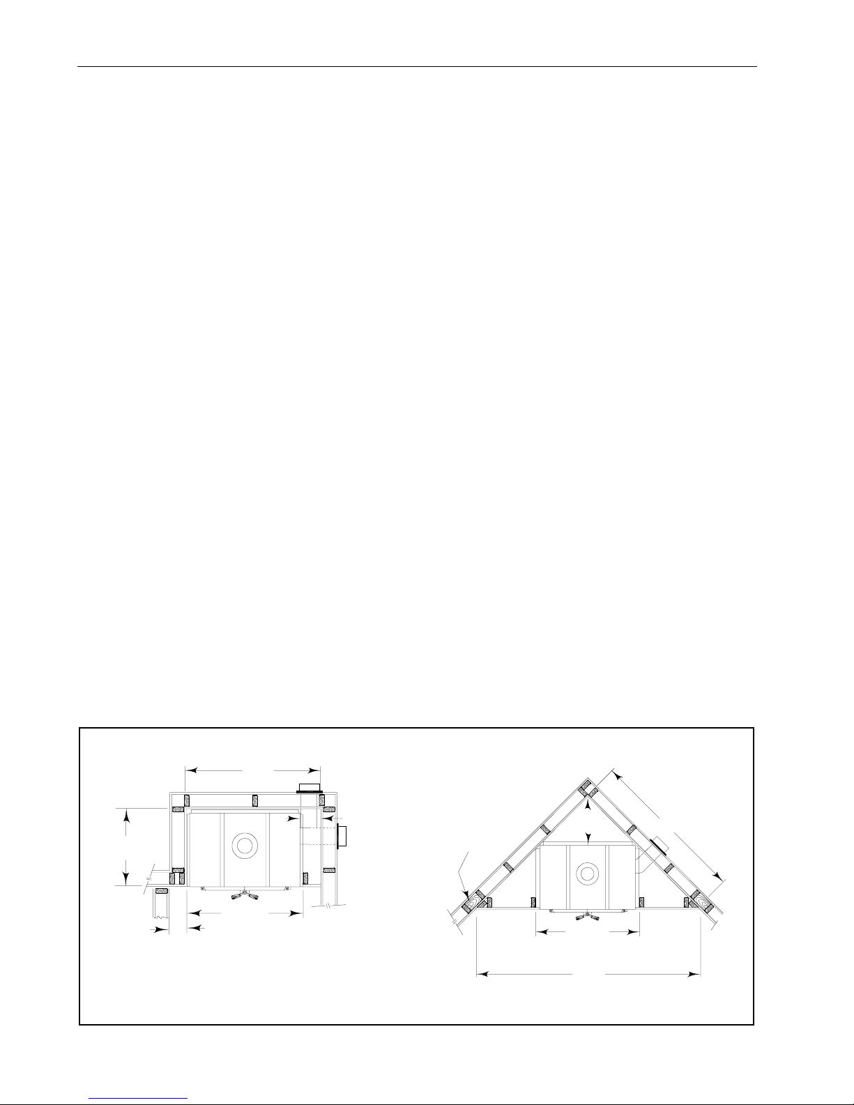
GRAVITY VENT SYSTEM (option)
If there are areas in your home that you would like to
heat either in an upper level or an adjacent room, the
gravity vent system can provide this heat without the
use of a blower. It is controlled by a gravity vent damper.
The handle is located between the top louvres of the
fireplace. Simply turn the lever to adjust the air flow
through the gravity vent ducting. As the hot air rises, it
will be distributed through the insulated ducting to the
outlet (See Options: The Gravity Vent System FD-V).
CENTRAL HEAT SYSTEM (option)
You have the option to heat remote rooms in your home
with the heat generated by your fireplace. If this option
is installed, there will be a wall thermostat installed in
the main room you want to heat, away from the room
which contains the fireplace. This thermostat controls
the blower, which brings air to the other rooms in your
home, keeping them at the temperature you desire.
When the blower is running, it takes air from the room
the OPEL 2000 is in, draws it around the fireplace and
distributes it (See Options: Central Heating System FD-
HC6/FD-HB6).
NOTE: The blower (FD-HB6) can push warm air either
up or down, and can also be zone controlled ( See Op-
tions: Zone Heating).
HINT: If some evening you would like to enjoy the ambi-
ence of the wood flame, but you are a little too warm,
turn up the central heating thermostat and open a win-
dow by the thermostat. This will keep your room in front
of the fire from getting too warm.
CATALYTIC COMBUSTOR (option)
If the OPEL 2000 is equipped with a catalyst, it ignites
creosote-forming gases in wood smoke at significantly
lower temperatures. As a result, you get less creosote
and more heat from your fire at low to medium burn
rates. Less fuel goes up your chimney in the form of
smoke. In addition to the list on page 3, DO NOT burn
chemical chimney cleaners, as they can contain con-
taminants that will render the catalyst inoperative.
The catalytic option comes with a bypass damper which
serves two functions:
a) to eliminate smoking into the room when the
doors are opened.
b) to allow the fire to start quickly when the
fireplace is cold.
Make sure the bypass damper above the right door is
pulled all the way out before opening the doors. When
starting a fire, the bypass damper should be left open
long enough to establish sufficient draft (approximately
30 minutes).
The temperature in the firebox and the gases entering
the catalyst must be raised to at least 500° F for cata-
lytic activity to be initiated. When you start the fire,
keep a medium to high fire for about 30 minutes to sta-
bilize the catalyst at a sufficient operating temperature.
If the fire is allowed to die down too soon after starting,

OPEL 2000 5
the catalyst may stop working. After the 30 minutes of
a medium to high burn, however, the catalyst will oper-
ate with the heat generated by the burning smoke, even
with a low fire.
OPERATION
LIGHTING
Slide the draft control under the doors all the way to the
right. Light a fire in the fireplace, starting with paper and
kindling only. Then add 2-3" diameter wood. After the
fire is established, close the doors to prevent overheat-
ing (see the Combustion Control section). Never use
any flammable liquids. Once a coal bed is established,
add standard cord wood. Leave the draft control open
until the fire is well lit, then adjust it to the level you
desire.
WARNING: Do not use a grate or elevate the fire.
THE FIRST FIRE
Before the first fire, be absolutely sure to wipe off all
fingerprints and debris from the gold plating. The
plating undergoes a sealing process during this first fire,
and the acid from your finger prints will permanently etch
the gold plating. You will experience a slow start-up
during the first fire. The refractory bricks still contain
moisture and take a good hot fire to get rid of the mois-
ture. While there is moisture in the bricks, the bricks
will be black with smoke deposits. When the moisture
is gone, the bricks will be white. You may also experi-
ence a slight odour during the first few fires. This odour
results from the curing paint and the burn-off of oil.
Figure 1: Bypass control with extension rod
fireplace face
thick facing pull hook
rod extension
decorative collar
set screw
bypass eye
handle
REFUELLING
Fuel wood can be of any species. However, ensure that
the wood is well seasoned and kept under cover. Six-
teen to eighteen inch lengths work the best.
NOTE: The central heat and internal blowers, if installed,
should be shut off during refuelling.
The doors should be opened slowly, moving both
doors together, to keep smoke from spilling into
your room. If you do have smoke spillage, check
to see that all kitchen and bathroom fans have been
shut off. They can cause a vacuum in the house,
which pulls smoke out of the fireplace.
If you have the OPEL 2000 with the catalyst: After
refuelling a cool fire or a fire that has burnt down to a
cool coal bed, operate the fire at a medium to high burn
rate for at least 10 minutes to ensure that the catalyst
reaches operating temperature.

OPEL 2000 6
MAINTENANCE
CLEANING
The high-heat paint and gold plating can be cleaned with
a soft moist cloth. Use a mild detergent and water. Do
not use abrasive cleaners!
ASHES
Clean the ashes before they become too deep, i.e.,
before you have a spillage problem when opening the
doors.
Ashes should be placed in a metal container with a tight
fitting lid. The closed container of ashes should be placed
on a noncombustible floor or on the ground, well away
from all combustible materials, pending final disposal. If
the ashes are disposed of by burial, or otherwise locally
dispersed, they should be retained in the closed con-
tainer until all cinders have thoroughly cooled.
DOORS
Keep the door latch and hinges lubricated with all-pur-
pose grease at least annually. To adjust the door closer,
tighten the Allen screw (as shown in figure 2) to ensure
that the door closes tightly. The hinges are adjustable
by removing the cap on top, and loosening the nut un-
derneath (picture 1). The hinge pins are manufactured
off-center to facilitate easy adjustment. With a flat screw-
driver, the pins can be turned so that the doors seal well
and fit with each other (picture 2). After adjustment,
tighten the nuts, holding the hinge pins in place with the
screwdriver, and replace the hinge caps.
If the door seal is damaged to the point where it does
not seal tightly, replace the gasket. The gasket replace-
ment kit (part FD-GRK2) is available from your dealer.
adjust here
Figure 2: Doors adjustment
loosen
tighten
Cap
Screw
Picture 2
It is normal to push on the handle to close the doors
(picture 3). To verify that the doors are well sealed, in-
sert a piece of paper between the door and the fireplace
(picture 4). On the top part, you should not be able to
pull out the paper without tearing it. On the side and
bottom part, you should be able to pull out the piece of
paper with some resistance (picture 5).
The doors sealing is the most important factor that
affect the burning control on the Opel 2000 fire-
place. Make sure that they are well sealed.
Picture 1

OPEL 2000 7
Picture 3 Picture 4
GLASS
In a controlled combustion firebox, temperatures are not
always high enough to keep the glass perfectly clean.
A good hot fire in the morning usually cleans off most of
the deposits that have accumulated during the night.
Remember the drier the wood, the cleaner the glass. A
word of caution: although heat will not break the glass,
a good blow can. Be careful not to hit the glass.
WARNING: Never clean this glass with an abrasive
cleaner. Use only a cleaner recommended by your dealer.
Never clean the glass while it is hot. You risk get-
ting a serious burn.
If your glass breaks:
See your dealer for the exact replacement glass. If the
gasket is damaged, it must be replaced with the identi-
cal kind (R7002). Place the gasket on the door frame
between the door and the glass (it is self-sticking).
1. Remove the door from the fireplace by lifting it off the
hinges.
2. Remove the clips holding the glass.
3. Clean out any bits of glass and dirt from the gasket.
4. Place the new glass into the opening and replace the
clips being careful not to over-tighten the screws.
5. Check the glass by trying to move it back and forth.
It should feel snug, but move slightly without too much
effort.
GOLD PLATING
If you have gold doors or gold louvers, you will be happy
to know that they will not tarnish however, they are not
scratch resistant. They require a totally abrasive free
cleaner. Use only mild soap and warm water to clean
the gold when the surface is cool. The use of any
household cleaner, such as Windex, abrasive cleaners,
or any form of acid, may permanently etch or remove
some of the gold plating. Before every fire, be abso-
lutely sure to wipe off all fingerprints from the gold plat-
ing. Acid from debris or your fingerprints may perma-
nently etch the gold plating.
Picture 5

OPEL 2000 8
CHIMNEY CLEANING
Check the chimney for creosote build-up every week
until experience shows how often cleaning is neces-
sary. A build-up of 1/4 inch or more should be cleaned
mechanically before more creosote accumulates. Use
a wire brush that fits correctly into the chimney. The
baffle in the firebox must be removed to gain access to
the flue from below.
Baffle removal:
1. Remove the secondary air tube and the refractory
liners.
2. Slide the baffle towards the front of the fireplace and
rotate it so that you can lower it to the bottom of the
fireplace opening.
3. Remove the baffle through the door opening.
Follow the reverse procedure to re-install it.
PAINT
You may touch up the face of the OPEL 2000 with
STOVE BRIGHT Flat Black high temperature paint. The
correct paint is available from your dealer. When you
paint the face of the fireplace, remove the gold items
(i.e., doors and louvers), and cover the area surrounding
the fireplace with newspaper. Follow the directions out-
lined on the spray can. DO NOT attempt to paint while
the fireplace is still warm. Keep the spray can away
from any source of heat or open flame. Ensure that there
is adequate ventilation in the room from the time you
start painting until the paint is dry.
CATALYTIC COMBUSTOR (option)
The catalyst is warranted by the catalyst manufacturer,
please insure that you keep the warranty card. If the
catalyst fails, it should be replaced withApplied Ceram-
ics Model 3621202-52-C. The dimensions of the cata-
lyst are 3.875" x 12.25" x 2".
It is important to periodically monitor the operation of
the catalyst to ensure that it is functioning properly and
to determine when it needs to be replaced. A non-func-
tioning catalyst will result in a loss of heating efficiency,
and an increase in creosote and emissions.
Catalysts should be visually inspected at least three
times during the heating season to determine if physi-
cal degradation has occurred. Actual removal of the cata-
lyst is not recommended unless a more detailed inspec-
tion is needed because of a noticeable decrease in per-
formance.
You can get an indication of whether the catalyst is
working by comparing the amount of smoke leaving the
chimney when the smoke is going through the chimney
after light-off has been achieved, to the amount of smoke
leaving the chimney when the bypass damper is open:
1. Light the fire in accordance with the instructions un-
der lighting. After the fireplace is warm, set the manual
control (and the thermostat, if this option is installed) to
low.
2. With the bypass damper closed, the smoke is routed
through the catalyst. Go outside and observe the emis-
sions leaving the chimney.
3. Open the bypass damper and again observe the emis-
sions leaving the chimney.
Significantly more smoke should be seen when the ex-
haust is not routed through the catalyst, i.e., with the
bypass damper open. Be careful not to confuse smoke
with steam from wet wood.
The catalytic combustor is self-cleaning, and requires
very little maintenance. Any loose ash should be re-
moved with a paintbrush. If the catalyst is plugged with
creosote, you may try burning it off by leaving the by-
pass damper in a partially open position and pushing
the draft control all the way to the right. You may also
burn off the excess creosote with a propane torch.
WARNING: Do not use sharp or hard tools to clean the
catalytic combustor as this will damage it.
Catalyst removal and replacement
1. Remove the screws holding the brackets, one on each
side of the catalyst.
2. Carefully ease out the catalyst, using a knife blade if
it is tight.
3. Replace the catalyst the same way it was removed.
If the gasket is loose, re-cement it to the outside
using a silicone adhesive. A damaged gasket should
be replaced with 3M Interam 1/16 x 2 x 36.

OPEL 2000 9
Figure 3: General assembly
B-vent components for the
gravity system only.
(or UltraBlack double wall
connector made by ICC)
24 minimum depth
of opening
ceiling clearance
(minimum from the top of
the fireplace)
25 for vented enclosure
37 for sealed enclosure
see the manual for flue
height requirements
the central heat blower
may be installed on the
left side
gravity vents may be
installed on the left, right
or both sides
5 wide sheet metal
spark guard
electrical knockouts
fresh air hood
radiation
shield
gravity vent
damper handle
The hearth can be made of
any permanently affixed,
non-combustible material
ceiling
radiation shield
and storm collar
roof flashing
storm collar
rain cap
hearth extension
header
back draft damper
central heat blower
MICORE BOARD
insulation material.
see page 16

OPEL 2000 10
INSTALLATION
Check local codes concerning restrictions and installa-
tion requirements in your area.
WARNING: Remove the doors before installation and
place them in a safe area to reduce the possibility
of:
a) Vandalism
b) Sub - trade tool abrasion, chipping, or
breaking of glass.
c) Gold finish damage because of muriatic acid,
plaster, cement, paint and harmful sprays or
liquids.
NAILING STIPS
Three (3) nailing strips are included with the OPEL 2000.
Those nailing strips must be installed on the fireplace
before its installation. The three strips (two for each
side and one for the top) are screwed on the unit (see
figure 13). Use the screws supplied with the fireplace.
Make sure that the nailing strips are fastened before
framing in the fireplace.
LOCATION
Your OPEL 2000 fireplace may be installed in many
different ways (see figure 4) without any special floor
reinforcement.
WARNING: If this fireplace is not properly installed, a
house fire may result. For your safety, follow the instal-
lation directions and clearances.
1. Note the location of roof and floor joists. Choose a
location that does not require cutting them.
2. Do not build shelves or cupboards in the area above
the fireplace. This space must be kept empty.
3. If at all possible, run the chimney up the inside of the
house. If it must be run up outside, it should be en-
closed in an insulated enclosure (see Installation:
Chase Enclosure). Remember, a cold chimney
causes poor draft!
CEILING CLEARANCE
Ceiling clearance is the distance from the top of the
fireplace to the ceiling.
If the space between the top of the fireplace and the
ceiling joists is less than 37 inches, the enclosure
around the fireplace MUST be vented. Place a mini-
mum 3" X 10" vent grille into holes cut within one foot of
both the floor and ceiling levels, to allow room air to
circulate through the fireplace enclosure and reduce heat
build-up. These vent grilles may be placed vertically or
horizontally. Under no circumstances is the distance
between the ceiling and the top of the unit to be less
than 25 inches (see figure 3).
OUTSIDE AIR DUCT
After the fireplace is correctly positioned, connect the
combustion air inlet to the outside (see figure 5).
1. Find a convenient location for the combustion air duct
and register. The location of the register may be above
or below floor level.
42
37 1/2
24
5 1/4 min. to side wall
82
37 1/2
18
frame opening
block
58
Figure 4: Location dimensions
6 when space is
needed for the outside
air duct

OPEL 2000 11
2. Make a 5 1/4" hole in the outside wall of the house.
Mount the register in the hole from the outside with the
inlet facing down.
3. Place the insulated flexible duct over the register tube
and outside air connector sleeve. At both ends, care-
fully pull back the insulation and plastic cover, exposing
the flexible duct. Then at each end, attach the duct with
metal screws to the inlet and tube. Carefully push the
insulation and cover back over the duct. Tape the plas-
tic cover in place with the 2" aluminum duct.
CAUTION: When running duct around corners, be sure
to prevent crimping that would restrict the combustion
airflow.
Use a 5" diameter insulated duct rated at over 200° F.
Figure 5: Outside air connection and installation options
outside air connection
OPEL 2000
2 aluminium duct tape
insulated flexible air duct
outside air register
outside wall
12
Our testing has shown that as long as the 5" diameter
insulated duct is utilized properly, there is no restriction
on the length of the run. It is recommended that the
duct does not exceed 12 ft. vertical height rise above
the base of the unit. The air inlet should never be less
than 5 ft. below the top of the chimney flue.
Outside air door
The Opel 2000 is designed to use outside air instead of
inside air for combustion but you may choose to use
inside air for combustion air.To do so, open the sliding
door on the bottom inside right of the fireplace (behind
the bottom louver. Note that the fireplace uses outside
air when the handle is closer to the back of the fireplace
and inside air when its closer to the front. We
recommend the use outside air for combustion.

OPEL 2000 12
If the chimney is higher than 5 ft. above the roof, it must
be secured using a roof brace.
4. Put the roof flashing into place. Seal the joint be-
tween the roof and the flashing with roofing tar. For slop-
ing roofs, place the flashing under the upper shingles
and on top of the lower shingles. Nail the flashing to the
roof using roofing nails.
If the chimney is enclosed to the roof:
- USA: use a vented flashing.
- CANADA: use a vented flashing or a
roof radiation shield (ERRS)
and a regular flashing.
5. Place the storm collar over the chimney and flashing.
Seal it around the chimney with silicone sealer (DO NOT
use roofing tar).
6. Fit the rain cap on the chimney. Secure it tightly in
place.
7. Wash the roof flashing with solvent (or vinegar if the
flashing is galvanized), then paint it with exterior paint.
8. Read the EXCEL Chimney installation manual con-
cerning requirements for supports, bracing, anchors, etc.
MASONRY CHIMNEY
Warning: When contemplating using an existing
chimney, it must first be thoroughly inspected by
an authority having jurisdiction to determine the
following:
1. It is a well constructed, lined masonry chimney, fully
in accordance with Local Building Codes and the Na-
tional Building Code of Canada (NBCC) 9.21 or NFPA
211.
CHIMNEY
This fireplace is certified for use with 7 ICC Model EX-
CEL chimney. The chimney system height from the
top of the fireplace must be a minimum of 12 ft. and a
maximum of 28 ft.
The minimum height of 12 ft. must be increased by ap-
proximately 1 ft. for every 2000 ft. elevation above sea
level. Every 30° or 45° elbow also increases the mini-
mum height by 1 ft. For example, if you are living 6000
ft. above sea level, your chimney must terminate at least
15 ft. from the top of the fireplace (12 ft. + 3 ft. for the
6000 ft.). See Table #1 for more precise recommended
flue heights.
CHIMNEY INSTALLATION
NOTE: The clearance between the chimney and com-
bustible material must be 2" or more. DO NOT fill this
area with insulation.
1. Cut and frame the required holes in the floor, ceiling
and roof where the chimney will pass through. Use a
plumb bob. The framing size is 13 1/4 square.
2. From below, install a radiation shield in each floor
through which the chimney passes. At the attic level,
install a radiation shield and a storm collar as shown in
figure 6).
3. Place the first chimney length on the fireplace. Se-
cure the chimney length to the fireplace with the three
screws provided.
The chimney must extend at least 3 ft. above its point of
contact with the roof and at least 2 ft. higher than any
wall, roof, or building within 10 ft. of it.
TABLE #1
MINIMUM RECOMMENDED FLUE HEIGHTS IN FEET
FROM THE TOP OF THE FIREPLACE
NUMBER OF ELBOWS
Elevation(ft) 0 2 x 15° 4 x 15° 2 x 30° 4 x 30° 2 x 45° 4 x 45°
0-1000 12 13 14 15 18 16 20
1000-2000 126 136 146 156 19 166 20
2000-3000 13 14 15 16 196 17 216
3000-4000 136 146 156 17 20 18 226
4000-5000 14 15 16 176 21 186 23
5000-6000 146 156 17 18 216 19 24
6000-7000 15 16 176 186 22 20 246
7000-8000 156 166 18 19 23 206 256
8000-9000 16 17 186 20 24 21 266
9000-10000 166 176 19 206 246 22 27

OPEL 2000 13
2. It has been thoroughly cleaned of any soot or creo-
sote residue and inspected to determine that it is in
good condition.
3. There is no attic insulation of any type in contact
with the chimney and no insulation stuffed in around the
chimney at any point, for any reason.
4. There is, as per NBCC 21.9.5 or NFPA211, the nec-
essary air space clearance at all points around the chim-
ney from floor to roof flashing. If the chimney is enclosed
in drywall, openings will probably be required in order to
verify clearances at all points.
5. Chimney will be used only for the fireplace and may
not be used to vent a furnace, water heater or any other
appliance.
6. If major repairs are required to meet the above con-
ditions, a new chimney should be constructed.
New chimney installation:
To ensure adequate draft and to facilitate cleaning, the
fireplace must be connected to the chimney using 7"
diameter EXCEL chimney with an elbow, as shown in
figure 9. An ICC 7" rigid stainless steel liner and a 45°
stainless steel elbow are attached to the chimney and
secured in place using a liner
adapter (#FD-M). If you use a 6 x
10 clay liner you will need to
ovalize the stainless steel liner
to fit into the clay liner. It is rec-
ommended that you position your
fireplace before building the chim-
ney. The factory built chimney
sections can easily be installed
as the layers of brick are being
placed.
Note: If the ceiling is high enough
some vertical chimney can be
installed before the 45° or 30°
elbow is installed.
Existing chimney
installation:
If it is difficult to install rigid stain-
less on an existing chimney, a
listed stainless steel flex liner
can be used. Special care is to
be taken when installing the flex-
ible liner. A positive connection
is assured with the masonry
adaptor (part FD-M) available from
your dealer. The stainless steel
flex liner connects to the ma-
sonry adaptor with a flexible/rigid
adaptor (part LAF) and is secured
with the 3 stainless steel rivets
provided. The masonry adaptor is
then secured to the Excel chim-
ney with the 3 screws provided.
The stainless steel liner fits in-
side the clay liner all the way to the top of the masonry
chimney. It is not meant to replace the clay liner. After
mortaring in place, the connection should not be visible.
Care must be taken when cleaning to ensure that the
stainless steel flex liner is not dislodged.
As depicted in Figure 7, the EXCEL chimney is to be a
minimum of 18" from the connection point at the elbow
to the masonry adaptor. The uppermost part of the metal
chimney where it enters the masonry chimney must be
a minimum of 12 inches from the ceiling.
Figure 6: Chimney Installation
rain cap
min. 2 ft.
min. 10 ft.
storm collar
flashing
min. 3 ft.
storm collar
radiation
shield
WARNING: DO NOT PACK RE-
QUIRED AIR SPACES WITH INSU-
LATION OR OTHER MATERIALS
1-hour fire rated enclosure required
when chimney passes occupied living
space (closets, etc.). 2 min. clearance
from chimney.
min. 2
37 min. (84 from
base to ceiling) for
sealed enclosure
25 min. (72 from
base to ceiling) for
vented enclosure
OPEL 2000
louvred vents
NOTE: openings must be
framed to adequately
support any chimney
supports and roof assem-
blies

OPEL 2000 14
1. Sight-in and mark the outline of where the factory-
built chimney will penetrate the masonry chimney.
2. Using a large (3/4" - 2") masonry drill bit, drill a hole
exactly in the center of the oval outline. With a masonry
hammer and drill, slowly enlarge the hole to the size
required. Remember to work from the center out. Be
especially careful with the clay liner behind the brick
because three sides of it must stay in place.
3. Bring the stainless steel liner down from the top of
the chimney. If you are using a rigid liner you will need
enough room to secure an elbow to it with at least two
screws. For chimneys with less than 10" X 10" inside
you may find it easier to install a flex liner and secure
the end with a special adapter (part #LAF) available from
your dealer.
4. Move the fireplace forward enough to install the length
of EXCEL chimney then move the fireplace back into
position as you connect the masonry adaptor to the
EXCEL chimney.
CHASE ENCLOSURE
If the chimney runs up the outside of the house, it must
be enclosed in a chase structure. It is best to locate the
chase away from any overhead obstructions and meet
all clearances from such objects. The chase should be
constructed in such a way that it is an extension of the
home. It should be well insulated between the footings
and the floor of the home to prevent heat loss. If the
climate in your area is mild, insulate the chase at least
to the first fire-stop. If the climate
in your area is very cold, insu-
late the chase to the top to keep
the flue warmer, to increase the
draft, and reduce creosote
buildup.
NOTE: In USA if the chase is
enclosed or flashed to the roof
as shown in Figure 9, then the
flashing must be vented.
If required by local codes, make
certain that the walls have been
properly insulated, vapor sealed
and sheathed with a fire rated
gypsum board (see figure 9).
REMEMBER: Check local
codes concerning installation
requirements and restrictions in
your area.
RADIATION SHIELD
A radiation shield must be placed where the chimney
passes through each floor level overhead. This will as-
sist in retarding any spread of fire and act to contain the
fire within the area below the fire-stop.
Figure 8: Offset chimney installation
storm collar
radiation
shield
radiation
shield
3 metal
screws in
each joint
offset
rise
use offset
support
Excel liner listed ULC-S635,
ULC-S640 and UL1777
clearance as per NBCC 9.21.5
or NFPA 211
masonry adaptor
(FD-M)
12 min. to
combustible
ceiling
Figure 7: Connection to masonry chimney
metal
firestop
Excel elbow
No combusti-
ble material in
this area
Excel 7 chim-
ney 18 min.
length

OPEL 2000 15
OFFSET CHIMNEY
Maximum offset angle: 45°
Maximum number of elbows: 4, resulting in two
(2) offsets.
An elbow may be installed directly on top of the fire-
place if required.
Use the offset option if you need to clear a joist or pass
around a cupboard.
Install the fireplace and chimney as described earlier.
When you require an elbow, proceed as follows:
1. Install the required elbow. Turn it in the desired direc-
tion, and fasten it to the other section with the 3 metal
screws provided at the joint.
2. Install enough lengths to obtain the desired offset.
Secure each joint with 3 metal screws.
3. Use another elbow to return the chimney to the verti-
cal direction.
4. Install a roof support, or an offset support at each
offset to support the weight of the flue (elbows are not
designed to support a flue above an offset).
FRAMING IN
The enclosure walls can be framed with any suitable
materials (2x4 or 2x6 studs, plywood, gypsum board,
etc.). Because of the high heat output potential of the
OPEL 2000, combustible material must NOT go closer
to the fireplace than the standoffs, top, back and sides.
If you like, framing can be set back to allow the facing to
be flush with the front of the fireplace.
Figure 9: Chimney installation with chase enclosure
fire stop, joist radiation shield
10 ft.
OPEL 2000
chase liner of fire rated gypsum
board is recommended (may be
required by local authorities)
insulation
2 ft. 18 min.
storm collar
metal chase
flashing*
2 min.
clearance to
combustibles
* In USA: Use vented flashing
In CANADA: Use Roof Radiation Shield
(ERRS) and a regular flashing

OPEL 2000 16
Figure 11: Offset chimney through a wall
10 ft.
2 min. to
combustibles
2 ft.
radiation
shield and off-
set, roof or wall
support
OPEL 2000
flashing*
18 min.
non-combustible
flooring
Z-shaped spark guard for raised installa-
tion must be custom supplied by installer
(minimum 26 gauge steel)
raised platform
Figure 10: Z-shaped spark guard
SPARK GUARD
Install a 5" piece of sheet metal centered
under the joint between the fireplace and
the hearth extension. This will make cer-
tain that sparks cannot lodge in the crack
and start a fire. If you are preparing a
raised installation, then a Z shaped
spark guard must be installed. The height
of the Z-shaped hearth guard must equal
the distance between the floor and the
base of the unit. The minimum depth the
spark guard must extend beneath the
OPEL 2000 is 2 1/2 inches. The spark
guard must run the full length of the fire-
place. (Z-SHAPED GUARD NOT SUP-
PLIED)
MANTEL
A masonry or other non-combustible
mantel may be placed directly above the
top louvers. If a wood or other combustible
mantel is desired, then it must be at least
28 inches above the top of the door
opening (see figure 14).
HEARTH EXTENSION
The area immediately in front of the fireplace must be
protected by a non-combustible material such as brick,
tile, stone, or slate. The protection must extend at least
16" in front and 8" on both sides of the fireplace open-
ing. There is no minimum thickness required for the
hearth extension.
MICORE BOARD
This piece needs to be installed in the USA only.
The OPEL 2000 must use a 3/4 Micore 160 board or
equivalent with an R value of 1.2 or greater. - unless it is
raised at least 4 inches above the base of the hearth.
The Micore board is not as wide as the hearth require-
ments. Cut 3/4 plywood and put it on both sides to
meet the dimensions of your desired hearth.
If the fireplace is raised 4 or more, the area in front of
the fireplace just needs to be covered with a non-com-
bustible material such as metal, brick, stone or slate, it
does not require the micore board. There is no mini-
mum thickness required for this non-combustible hearth
extension. The 5 wide spark guard must be installed
underneath either the hearth extension or the Micore
board.
Note: if the OPEL 2000 is installed on a concrete floor,
the Micore board and spark guard are not required.
* In USA: Use vented flashing
In CANADA: Use Roof Radiation Shield
(ERRS) and a regular flashing

OPEL 2000 17
47 1/4
23
38 1/2
16
12 max.
54
8 1/2 min.
from side
wall to
edge of
louvres
non-combustible
hearth
3/4 insulation
board (R1.2)
in USA
outside air
inlet must go
down to-
wards base
of unit
Figure 12: Clearance to combustibles
Figure 13: Unit dimensions
opening for cen-
tral heat or grav-
ity vent ducting 37
framing dimension
24
11 1/4
1 1/2
11 opening for gravity vent
only
7
49 3/4 to top standoff
25
5 3/4
39 1/4
1 3/4
18 7/8
29 1/2
36
1 1/4
1 1/2
3/4
1/2
11
Nailing strips

OPEL 2000 18
Figure 14: Clearance to combustibles
combustible top
facing may pro-
trude 1 max.
from the face of
the fireplace
28 min.
to mantel
(54 from
the base
of the fire-
place)
23 1/2 min. to
combustible
top facing
(49 3/4 from
the base of
the fireplace)
combustible
side facing or
surround may
extend 12
max. from the
face of the
fireplace
7 1/4 min. from door
opening to combus-
tible facing

OPEL 2000 19
OPEL 2000 OPTIONS
Just a few comments about your OPEL 2000 options.
The size and shape of your home and how you intend to
use your fireplace will determine the options you require.
For a basic, high-efficiency fireplace, you wont need
any options or electricity.
Automatic temperature control can be accomplished by
adding the thermostat option (part FD-HC4). The ther-
mostat automatically controls the amount of combus-
tion air to the fire, leaving your home at an even preset
temperature. If you seriously plan to heat your home
with the fireplace, the thermostat option will increase
comfort, end the fuss of continued manual adjustment,
and reduce wood consumption.
For more heat output and increased air circulation, you
throughout your home - even a couple of stories up or
down.
WALL THERMOSTAT (FD-HC4)
This optional kit allows you to control the temperature
by a remote mounted electric wall thermostat.
NOTE: It is strongly recommended that this kit be
installed during framing so that the wiring can be easily
hidden.
1. Remove both top and bottom louvers. They are held
in place by springs underneath, so push down from the
top, then rotate and pull forward.
2. The damper motor and transformer are mounted on a
bracket in the bottom right hand corner of the fireplace
(see figure 15).
Figure 15: Thermostat control installation
draft control
black
white
ground
(bare)
wall thermostat
(FD-HC4 kit)
terminal block
(cover removed)
damper motor
(FD-HC4 kit)
transformer
mounting
bracket
See wiring
diagram
Figure 34
keyhole with
pendant
stops
to thermostat
110V
pendant
and chain
(FD-HC4 kit)
screw
can add the internal blower (part FD-
HB5). For larger homes in colder
climates, this is an important option
if you plan to use the fireplace as a
serious source of heat.
NOTE: It will be difficult to install the
internal blower if wiring is not run during
framing. If there is any chance that
this option will be installed in the
future, power should be run to the
fireplace and wire must be run to a
switch box at a convenient place on
the wall for mounting the blower
control.
If you have rooms directly above or
adjacent to the room with the fireplace
that you would like to heat, you may
consider the gravity vent option (part
FD-V). The gravity vent distributes hot
air to these rooms and requires no
blower to assist its operation.
However, with the internal blower (FD-
HB5-N) installed, there will be some
increase in warm air movement to
rooms serviced by the gravity vent.
If you desire even heat throughout your
home strictly from your fireplace, or if
you want to move heat to a remote
area of your home, it is recommended
that you incorporate the central heat
option (parts FD-HB6, FD-HC6 and
FD-HC6-1). A thermostatically
controlled blower takes heat from the
fireplace, and distributes the warm air
top louvres

OPEL 2000 20
3. BEFORE fastening the controls with the 2 screws
provided, thread the supplied chain through the spare
keyhole in the draft control and attach a pendant to the
end, just like the chain that is beside it. Let the chain
down on the same side of the heat shield as the existing
chain, and attach it to the lever on the damper motor
with another pendant. Push the pendant snug into the
hole in the lever. Then mount the controls to the bracket.
4. Adjust the chain on the draft control lever until it is
just snug but the damper is still closed. When the
damper motor is energized, the damper should open all
the way. Lock the chain onto the keyhole with another
pendant just like the chain beside it.
5. Wire the thermostat as shown in figure 15, making
sure the wall control is sufficiently away from the direct
radiation of the fireplace. Make certain that it is at least
10 ft. away from the fireplace, but in the same room.
CIRCULATING BLOWER (FD-HB5-N)
NOTE: It is important that the wiring for the blower kit is
installed during framing so that the wiring can be easily
hidden.
1. Remove the bottom louver. It is held in place by springs
underneath. Therefore, push down from the top, then
rotate and pull forward.
2. Hold the blower with the outlet facing up from the
back. Fit the blower through the louver opening.
3. Slide the blower into place between the two brackets
4. Mount the thermal switch as shown in figure 17. The
front face of the fireplace is bent into a flange just above
the lower opening. It has holes to hold the bottom louver
rods. The thermal switch mounts just to the left of the
Figure 16: Circulating blower
circulating blower
thermal switch bypass
terminal block
blower speed control
thermodisc
See wiring diagram
Figure 35
Figure 17: Circulating blower location (sectional view)
circulating blower
terminal block
mounting clips
thermal switch
louvre retention spring
bottom louvre
Table of contents
Popular Indoor Fireplace manuals by other brands

Somogyi Elektronic
Somogyi Elektronic home FKK 21 instruction manual

Valor
Valor 780MN Addendum to Installation Instructions

FMI
FMI B36 OWNER'S OPERATION AND INSTALLATION MANUAL

SUPREME
SUPREME VOLCANO PLUS owner's manual

IN & OUT HOUSE
IN & OUT HOUSE EF61D instruction manual

Desa
Desa VT32N Series OWNER'S OPERATION AND INSTALLATION MANUAL

Heatilator
Heatilator CONSTITUTION C-40 owner's manual

Town & Country Fireplaces
Town & Country Fireplaces TCWS54DST User instructions

Ecoflam
Ecoflam MAX GAS 350 P AB manual

Dimplex
Dimplex VERDI VER20 manual

Riello
Riello GAS 4 Installation, use and maintenance instructions

RSF Woodburning Fireplaces
RSF Woodburning Fireplaces OPEL+ KEYSTONE owner's manual