RTA Products TECHNI MOBILI RTA-913D User manual

REV.NTL-7315-0423
HOME OFFICE WORKSTATION WITH STORAGE
MODEL RTA-913D
ASEEMBLY INSTRUCTIONS
Thank you for purchasing our product
Scan QR to view full
assembly video
VIDEO

2
3
5
89
10 11
12 13
RTA-913D
P.2 P.2
MAIN PARTS LAYOUT (For reference)
HARDWARE LIST
TOOLS REQUIRED BUT NOT INCLUDED
PART QTY SIZE ITEM
C
D
E
F
M6x30
Wooden dowel
B
A
10
14
14
8
4
4
M5x31
Bolt
M12x9
Cam lock
M3.5x40
(Flanged head)
M3.5x40
(Flat head)
M3.5x25
PART QTY SIZE ITEM
I
J
Hammer
Phillips Screwdriver or power
drill with Phillips drill bit
K
L
M4x12
G
16
14
40
6
2
15mm plastic
adhesive cover
M4x23
Nails
12x12x6mm
Glide stud
128mm Handle
M
1Touch-up
1
4
6
7
M3x12
H
16
N
415x15x40mm
Angle bracket
O
2
Sets 13.75" Drawer
metal sliders,
Set of 4 pcs
RIGHT
LEFT
RIGHT
LEFT
"FLAT": 2 pcs per set,
go inside the cabinet
"L shape": 2 pcs per
set, go on the drawers
Or
P
1Mark eraser
Pencil

P.3 P.3
RTA-913D
BEFORE YOU START THE ASSEMBLY, PLEASE READ THE FOLLOWING TIPS AND WARNINGS.
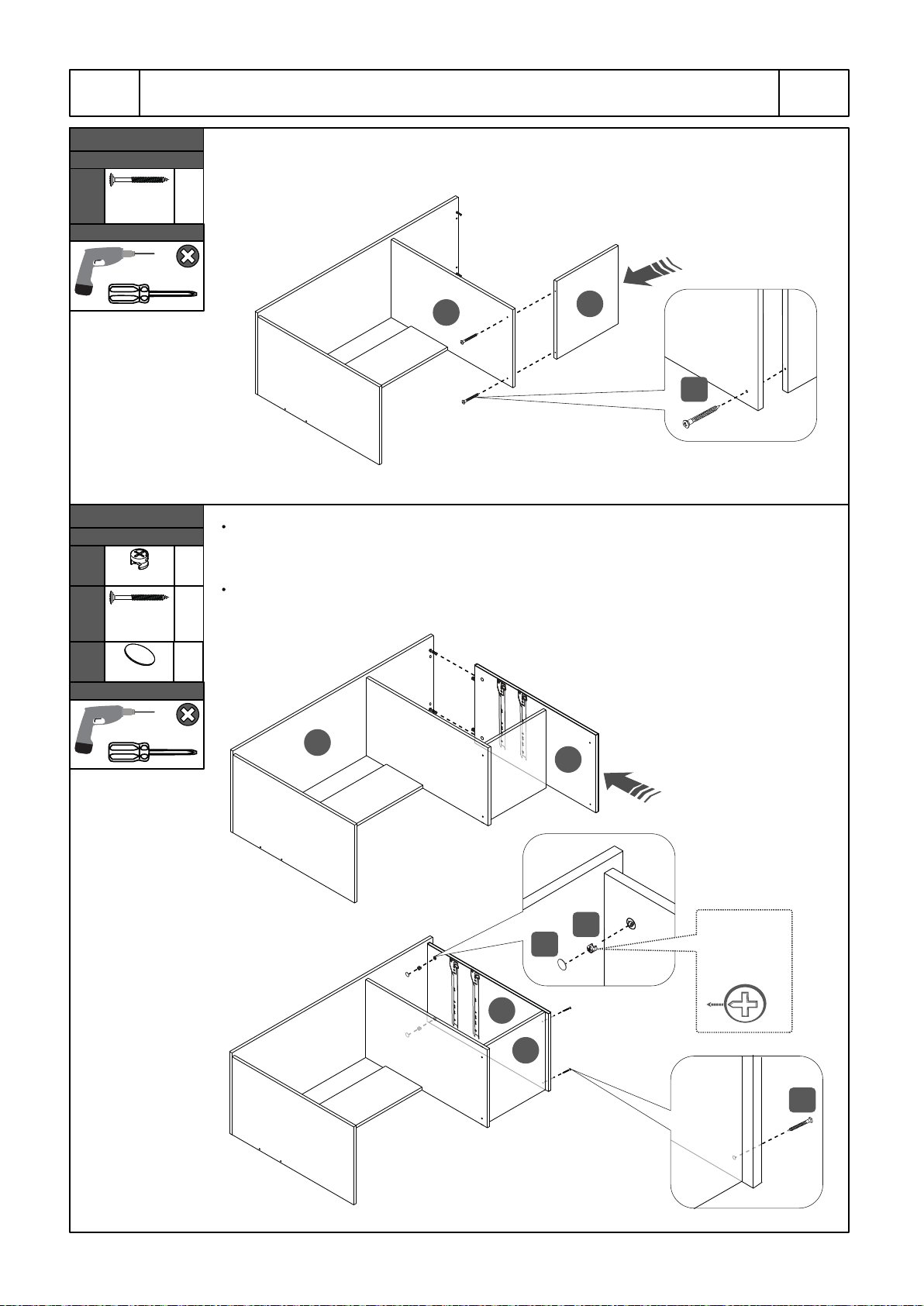
M6
30mm
M6x30
• Make sure you understand which
hardware will be used on each step. Using
the wrong size of screw, bolt or pin might
strip the threads or cause damage to the
part in which it is being used.
• To avoid misalignments, always leave the screws
loosely and do not tighten them until all the pieces
are positioned correctly.
• Do not overtighten or force the screws as they might
break, strip, damage the threads of the holes, or get
stuck inside the parts.
• If the hole seems to small for the screw, make sure
you are using the correct size of screw and/or that
you are installing it in the correct hole.
• Sometimes on the wood panels the laminate or
material might be covering the hole partially or
entirely, if there is no visible hole or if it looks too
small, pass and press the tip of your finger over the
area to feel its indentation, and carefully pierce the
laminate to uncover the hole underneath.
• Do not discard this manual or any of the packaging
material until the unit is completely assembled.
• Please read the assembly instructions throughly and
follow step by step.
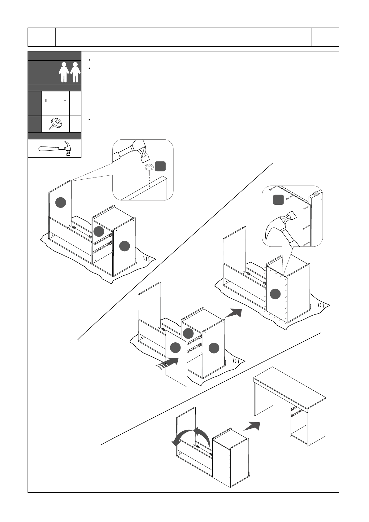
• The product assembles ONLY as shown in the
front page, with the drawers on the RIGHT side.
The drawers cannot install on the LEFT side.
Thank you!
12
Leave loose,
tighten all together
√
√
X
• The assembly might require of 2 persons for certain
steps. Before you start the instalation, make sure there
is someone else nearby to help you.
Do not
overtighten
• Please be kind to our planet, when done with the
assembly, recycle any of the packaging materials
that is accepted by your city or recycling service.

RTA-913D
P.4 P.4
1. Screw the bolt into the indicated hole on the
panel indicated in the assembly step.
CAM BOLT AND CAM LOCK TUTORIAL
THE INSTRUCTIONS BELOW
ARE NOT ACTUAL ASSEMBLY STEPS
This unit uses cam bolts and locks (also known as mini fixes).
If you are not familiar with this kind of hardware, the below is a tutorial
that explains how to use them on the steps where they are required.
2. Join the other panel (with the big hole) to the
panel with the bolt. If it comes with the cam
locks already pre-installed, make sure to align
them to receive the bolt's head (refer to point
3). There might be a very small gap between
the panels which is normal.
3. Insert the cam lock on the panel with the big
hole making sure it goes aligned to receive the
bolt's head.
4. Use a Phillips screwdriver to turn the cam
lock clockwise. This will lock the panels
togheter and also will close any gaps.
Cam lock
alignment
If the cam locks come
pre-in stalled, make sure they
are aligned (see point 3).
THE ASSEMBLY STEPS START ON PAGE 5
THIS IS ONLY
A TUTORIAL
THIS IS ONLY
A TUTORIAL
THIS IS ONLY
A TUTORIAL
THIS IS ONLY
A TUTORIAL

(Front)
RTA-913D
P.5 P.5
Attach the dowels Ainto the indicated holes on the side panels 2, 4and 6, and
to the drawer side panels 9and 10.
STEP 2
Hardware
ASSEMBLY STEPS
1
2 4 6
8
9
10
BBolt 14
Pcs
Tools (NOT included)
STEP 1
Hardware
AM6x30 10
Pcs
Tools (NOT included)
Or
(Front)
Attach the dowels Binto the indicated holes on the tabletop 1and the drawer
front panels 8.
10
9
(Top)
(Top)
(Front)
(Front)
(Front)
(Top)
(Front)
A
A
AA
8

(Front)(Front)
O
"Flat", LEFT
O
"Flat", RIGHT
(Front)
STEP 3
Hardware
O
2 "flat" pieces
per set:
2 "L shape"
pieces per set:
Grab both sets of sliders O(total 8 pieces) and separate them into 2 groups
according to their shape:
The "flat" ones will be used on the next step.
The "L" shaped will be used until step 12, set them aside.
(Front)
(Front)
(Front)
O"L" Shaped
O"Flat"
RIGHT
LEFT
The "flat" ones will be
used on the next step
.
The "L" shaped will be
used until step 12, set
them aside.
RTA-913D
P.6 P.6
6
O
4 "flat" pieces:
Use screws Hto assemble the "Flat" sliders Oto the panels 4and 6in their
respective sides (Left sliders to 4, right sliders to 6).
NOTES:
The wheels go towards the front of the panels.
Attach first on the front, through the 3rd hole on the slider.
The sliders will show 2 free holes above the wheels.
STEP 4
Hardware
HM3x12 8
Pcs
(Front)
(Top)
4
(Top)
46
Tools (NOT included)
Or
RIGHT SIDE
LEFT SIDE
(Front)
RIGHT
LEFT

STEP 6
Hardware
CCam lock 2
Pcs
This step
requires of
2 persons
DM3.5x40
(Flanged)
2
Pcs
Tools (NOT included)
Or
With the help of another person, join the middle panel 4to the tabletop 1,
insert the cam locks Cinto the holes of 4and turn them to lock the pieces as
explained in page 4. Cover the cam locks with stickers I.
Secure the middle panel 4to the back-left panel 3with flanged screws D.
ISticker 2
Pcs
(Front)
(Back)
RTA-913D
P.7 P.7
With the help of another person, join the left side panel 2to the tabletop 1, insert
the cam locks Cinto the holes of 2and turn them to lock the pieces as
explained in page 4. Cover the cam locks with stickers I.
Assemble the back-left panel 3to the left side panel 2with flanged screws D.
The screws go from the outside through 2and into 3.
STEP 5
Hardware
CCam lock 2
Pcs
1
2
3
CI
This step
requires of
2 persons
DM3.5x40
(Flanged)
2
Pcs
Cam locks
alignment
on 2
Tools (NOT included)
Or
D
3
4
1
4
ISticker 2
Pcs
3
CI
Cam locks
alignment
on 2
D
(Front)
(Front)

6
(Left)
RTA-913D
P.8 P.8
Assemble the lower panel 5to the middle panel 4with flanged screws Das
shown.
STEP 7
1
45
6
D
Join the right panel 6to the main panel 1, then insert the cam locks Cinto panel
4and turn them to lock the pieces as expalined in page 4. Cover the cam locks
with stickers I.
Secure the right panel 6to the lower panel 5with flanged screws Das shown.
STEP 8
ISticker 2
Pcs
Hardware
CCam lock 2
Pcs
DM3.5x40
(Flanged)
2
Pcs
Tools (NOT included)
Or
Hardware
Tools (NOT included)
Or
DM3.5x40
(Flanged)
2
Pcs
(Front)
(Front)
(Front)
5
C
I
D
Cam locks
alignment
on 6
FIRST:
THEN:
(Front)
(Front)

FIRST
Tools (NOT included)
Or
(Front)
(Back)
(Right)
(Left)
RTA-913D
P.9 P.9
With the help of another person, turn the unit upside-down over a large blanket
to protect the tabletop's surface.
One person will place and firmly hold the panel 7against the tabletop 1and the
side panels 2, 4and 6while the other person will install the angle brackets N
with screws Gexactly as adviced below:
- First place all 4 brackets flushed and distributed evenly along the panel, with
the first and last as close as possible to the ends.
- Begin securing the first and last bracket first as advised next.
- Secure the brackets first to the tabletop 1, then to the front panel 7.
- Finally, repeat the above for the 2 brackets that go in the middle.
STEP 9
Hardware
GM4x12 16
Pcs
2
4
6
This step
requires of
2 persons
N4
Pcs
Attach the end
brackets first
IMPORTANT:
■Please note that the top front panel 7 does not have predrilled holes or
any other markings for this step; that is the way it is manufactured.
■The assembly of panel 7 requires that it stays as still as possible, so a
second person should hold it in place firmly during the assembly.
■We recommend the use of a power screwdriver set at low torque.
■The panel not necessarily will install 100% perfectly, and small
misalignments and gaps are possible, and should not be of concern or
considered a product defect.
■If the misalignment or gap is very noticeable, you can remove the panel
and try to reinstal it, placing the brackets slightly to the left or right of their
original positions.
Flip upside-down
7
1
G N
Attach the end brackets first while
holding firmly panel 7
Screw to 1 first Then screw to 7
G
N
7
1
SECOND LAST

LAST
RTA-913D
P.10 P.10
Attach the glide studs Kto the bottom of panels 2, 4and 6as shown.
With the help of another person, center the back board 13, covering the
drawers' cabinet on the back, and secure it with at least 24 pcs of nails J.
IMPORTANT:
Make sure to insert the nails as straight as possible and centered on the profiles
of the panels to avoid going slanted or too close to the edges, as they could
chip/crack the panels.
With the help of another person, bring the unit upright.
STEP 10
Hardware
JNail
At
least
24
Pcs
This step
requires of
2 persons
K6
Pcs
Tools (NOT included)
2
4
6
K
FIRST
J
13
THEN
4
6
13

RTA-913D
P.11
Assemble the handle Lto the drawer front panel 8with screws Fas shown.
Assemble the drawer back panel 11 to the side panels 9and 10 with screws E.
8
11
F
EM3.5x40 4
Pcs
FM3.5x25 4
Pcs
LHandle 2
Pcs
L
P.11
E
10
9
11
Join the drawer side panels 9and 10 to the drawer front panel 8in their
respective sides, then insert the cam locks C in the side panels and turn them to
lock the pieces as explained in page 4.
Cover the cam locks with stickers I.
STEP 11
ISticker 8
Pcs
Hardware
CCam lock 8
Pcs
Tools (NOT included)
Or
I
C
Cam locks
alignment
on 9, 10
(Left)
(Right)
(Top)
(Bottom)
8
910
For each of the drawers:

RTA-913D
P.12 P.12
Assemble the "L" shaped sliders Oon their respective sides with screws H, but please note:
The wheels go towards the back of the drawer.
The sliders should not protrude from the bottom of the drawer, otherwise they
raise the drawer 1" more and won't fit in the unit.
O
4 "L" pieces:
HM3x12 8
Pcs
Or
O
H
H
O
LEFT
(Front)
(Back)
RIGHT
For each of the drawers:
Flip them upside-down and place on it the drawer bottom board 12, inserting
one end into the groove of the front panel 8, and use one nail Jto secure the
board to the back panel 11 as shown.
STEP 12
Hardware
JNail
At
least
13
Pcs
Tools (NOT included)
J
(Top)
(Bottom)
12
8
11
J
Place the "L" shaped sliders Oon the sides with their wheels facing towards the back, and
mark on the board with a pecil the holes that will be used to attach them to the drawer.
Remove the sliders, and secure the bottom board with at least 12 more nails Jmaking sure
not to block the marks where the sliders will be installed later on.
+
+
(Just one)
(Just mark
and remove)

Give yourself a nice pat on the back, you did a great job!
P.13 P.13
RTA-913D
ALL DONE!
You can use a rug damped with rubbing alcohol to remove the visible small stickers with
numbers on the pieces.
You can remove the visible numbers printed on the panels with the eraser P. Please make
sure that you don't confuse it with the Touch-Up Mwhich is used for another purpose.
You can use the touch-up Mto cover up small imperfections on the finish.
STEP 13
Hardware
MTouch-Up 1
Pc
PEraser 1
Pc
Touch-Up M
2
Eraser P
6
Use to cover up
imperfections
use to
remove
printed
numbers
Use to
remove
stickers
Rubbing
Alcohol
Insert the drawers into the unit, starting with the bottom one, and with the front
facing down at an angle. If the drawers don't seem to fit, review the assembly
done in steps 4and 12.
If the drawers stop or feel
like hitting something,
tighten all the screws as
flushed as possible so the
heads don't interfere with
the rollers.
The wheels from the
drawer must slide in the
middle of the sliders,
not on top on them.
Tighten flushed

P.14 P.14
RTA-913D
Clean the surfaces preferable with a clean cloth damped in a solution of mild soap and water,
then dry with a clean towel.
If you decide to use a cleaning agent, test first on an area hidden from view such as
underneath the tabletop.
Every 4 months, inspect the unit completely and make sure that all screws are tighten.
When transporting the unit to places far away, protect and secure the unit to avoid damage in
transit.
Shall any part of the unit become defective during the warranty period, replacement parts
might be available to you at no charge. Please refer to the last pages on this manual.
The warranty does not extend to regular wear and tear, nor the manufacturer assumes liability
for damages or consequences due to accidents, incorrect assembly, negligence, improper
use, modifications, or not heeding the above warnings.
WEIGHT LIMITS
CARE AND MAINTENANCE
WARNINGS
Do not exceed the indicated weight limits.
Do not expose the surfaces to direct sunlight or to extreme environmental conditions.
Do not use solvents or abrasive materials to clean the unit.
Do not sit on the unit or lean against it.
Do not allow small children to play under or over the unit.
Do not allow small children to reach inside the drawers or compartment without your supervision.
Do not pull, push or drag the unit to move it for more than 1 feet. The unit must be lifted by at
least 2 persons when moving in the same or adjacent rooms.
Before moving the unit, make sure to secure or remove any object that is heavy or might fall off.
Please note that lifting from the tabletop with too much weight on the product might lead to part
damage/separation.
When lifting the unit, use both hands and bend your knees, not your backs.
44 Lbs
(20 Kg)
15.5 Lbs
(7 Kg)
6.6 Lbs
(3 Kg)

P.15 P.15
RTA-913D
TECHNI MOBILI WARRANTY
RTA Products, LLC warrants to the Original Purchaser who acquired a new product from RTA
Products or its authorized resellers that this product will be free from defects in its workmanship
and materials, under normal use and service conditions, as described herein. "Defects" as used
in this warranty, is defined as any imperfections that impair the use of the furniture or product.
RTA Products LLC will replace any defective part, at its discretion, and without charge to the
original purchaser other than the freight from the end consumer to RTA Products.
Replacement parts can only be supplied if parts are available. Items out of production may be
unavailable. This warranty will be effective for the applicable time period beginning the date of
purchase on your original sales receipt. RTA product’s obligation under this warranty is limited to
repairing or replacing products or parts as provided herein. This product has been designed for
and is intended for office and home-office use only. This warranty is Original Purchaser’s sole
remedy for product defects, and this warranty does not extend to any product, or damage to any
product, caused by or attributed to abuse or misuse, products used for commercial or rental
purposes, use modifications of, or attachments to the product, and products or parts not used,
maintained, or extended hereunder is in lieu of any and all other warranties, express or implied,
including without limitations any implied warranty or merchantability or of fitness for a particular
purpose. Please note, all desks made with PVC Laminate surface should not be exposed to
direct sunlight, as it may damage the material. Damage of this nature is not covered under this
warranty.
RTA Products will not be responsible for indirect, special, incidental or consequential damages.
This warranty is limited to merchandise purchased in the Continental United States, excludes
AK, HI and PR. Some States do not allow the exclusion or limitation of incidental or
consequential damages, so the above limitations or exclusions may not apply to you. This
warranty gives you specific legal rights. You may also have other rights that may vary from state
to state.
RTA Products will advise you of the procedure to follow in making warranty claims. The following
are the procedures for warranty claims:
a. Call us Monday – Friday, from 9am-5pm (Eastern Time) at (866) 782-5520 to explain the
defect and give your name, address and phone number. Please have ready the model number
of our product, date and place of purchase. You can also write to us by e-mail to
b. If we determine that replacement will remedy the situation, and in order to determine the
extent or the cause of the defect, purchaser will need to send the part in question at purchaser’s
expense. Once we receive the part, we will examine it and determine whether the claim is valid
(or not), and then proceed to send the replacement. We will ship the replacement at our
expense.
DESKS/LAPTOP CARTS/FILE CABINETS: LIMITED 5-YEAR WARRANTY
Table of contents