Rubicon 480 User manual


CAUTION:
It is important that you read and understand this manual
in its entirety before using the machine to mitigate the
risk of personal injury or property damage.
Contents
Specifications 3
Safety Instructions 4
Operating Instructions 6
Handle Positions 9
Engine Manual 10
Tooling Position & Magnetic Plugs 13
Axle Height Adjustment 15
Gearbox Maintenance 16
Display Functions 17
Electrical Safety 18
Wiring Diagram 19
Main Machine Breakdown 20
Parts List 21
Problem Solving 22
Warranty 23

Specications
3
RUBICON 480
Weight 160kg (182kg including weights)
Head Pressure 112kg (134kg with weights on head)
Dimensions 543 x 1007 x 1447 (Width x Height x Length)
Rated Voltage 230 Volt 50 Hz
Rated Watts 2200W
Grinding Path 480mm

Safety Instructions
1. Read and understand the instructions on the machine and in this manual.
2. Equipment should only be operated by trained personnel who are in good
physical condition and mental health (not fatigued). The operator and
maintenance personnel must physically be able to handle the bulk, weight
and power of this machine.
3. The RUBICON 480 must only be used in accordance with the instructions
given in this manual. Any other work methods or practices are not approved
and could result in serious injury or death.
4. The handle of the RUBICON 480 can be locked into different positions:
OPERATE, TOOLING and LIFT/STORAGE. Diagrams of these positions are
available in the Handle Positions section of this manual. The appropriate
circumstances to use each position is described throughout the manual.
5. This machine is intended for operation only by a single person: ‘one
machine, one operator’. Always be mindful of people working in the same
area and maintain a safe operating distance to avoid injury.
6. This equipment is intended for commercial use.
7. For the safety of the operator and others working in the area, ensure guards
and shrouds are always in place and never run the machine without them.
8. There are weights on brackets at the base of the machine’ handles to assist
operating the machine. The weights must be removed from the handle
before the machine is folded to the TOOLING or LIFT/STORAGE position.
9. Never leave the machine unattended when it is operating.
10. The wear and tear on the magnetic plugs must be checked every three
hours of use.
11.
concrete, terrazzo and other solid surfaces.
12. The handle height position is adjustable for comfortable operation of the
RUBICON 480. The height is adjusted at the OPERATE position, next to the
lock mechanism.
13. The machine must only be started if the handle is in one of the three
OPERATE positions. Never attempt to adjust the handle position when the
machine is in operation.
14. Never start or run the machine with the handle folded in the LIFT/STORAGE
position or when disks are not in contact with the ground.
15. Do not lend or rent the machine without providing a copy of this Safety,
Machine & Operator’s Manual + Parts Listing booklet.
4

16. Wear protective work wear appropriate for the job and for the work
environment. In addition to the suitable work clothing, additionally include
safety shoes, hard hat, hearing protection, non-fogging vented safety goggles,
and proper respiratory protection mask to prevent dust inhalation. Personal
safety must always be observed when operating the RUBICON 480.
17. Stay a safe distance from the machine’s moving parts when operating and
ensure loose clothing is secured and kept away from moving parts. Failure to
comply could result in bodily injury.
18. Do not modify the machine in any way. Only use the original manufacturer’s
parts and accessories.
19.
with the machine.
20. Before changing diamonds and other accessories or servicing the machine,
ensure all moving parts have completely stopped and disconnect the power
or spark plugs.
21. Never operate the machine in wet and rainy conditions or if there is heavy
moisture present.
22.
when the engine is cool and ensure the area is well ventilated area.
23. WARNING: POISONOUS EXHAUST GASES. Do not operate petrol powered
equipment, including generators, without adequate ventilation. Carbon
monoxide is an invisible, odourless gas that can harm or kill.
24. Do not operate the RUBICON 480 with any of the doors or panels removed,
open or not properly secured.
25. The RUBICON 480 can produce sound levels in excess of 85db. The operator
must wear approved safety hearing protection.
26. Do not allow the power supply cord to come into contact with the cutting
blade, head, or other moving parts on the machine.
27. WARNING: As with any diamond tooling, breathable silica or other hazardous
dusts may be generated by use and maintenance of this machine. The
dust can cause severe and permanent lung damage, cancer, and/or other
serious diseases. Do not breathe the dust. Do not rely on your sight or smell
to determine if dust is in the air, as silica may be present in the air without
a visible dust cloud. Appropriate respiratory protection must be worn when
operating and maintaining this equipment.
5

28. Wear protective work wear appropriate for the job and for the job and work
environment. In addition to the suitable work clothing, additionally include
safety shoes, hard hat, hearing protection, non-fogging vented safety
goggles, and proper respiratory protection mask to prevent dust inhalation.
Personal safety must always be observed when operating the RUBICON 480.
29. The RUBICON 480 must only be used in accordance with the instructions
given in this manual. Any other work methods or practices are not approved
and could result in serious injury or death.
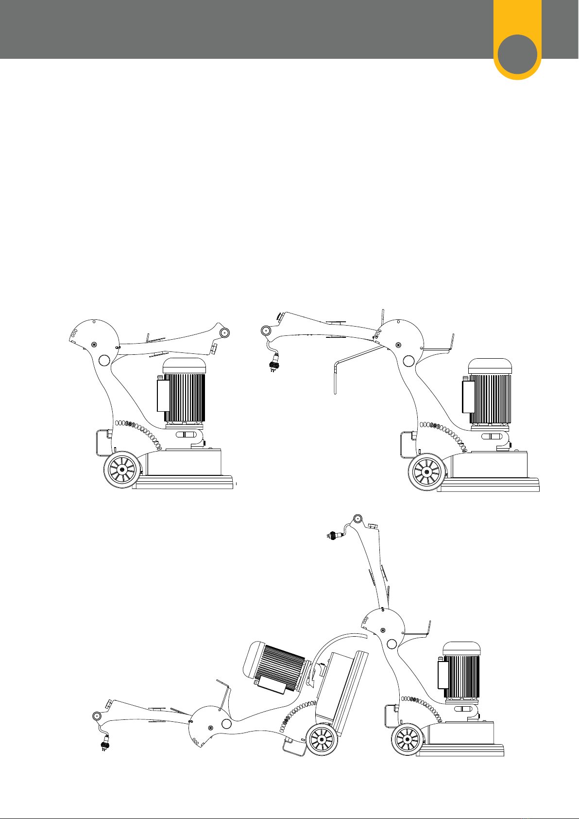
30. WARNING: Disconnect the power before moving the handle to the
TOOLING or LIFT/STORAGE position.
31. WARNING: POISONOUS EXHAUST GASES. Do not operate petrol powered
equipment, including generators, without adequate ventilation. Carbon
monoxide is an invisible, odourless gas that can harm or can kill.
32. Be sure all equipment is tested and tagged prior to use on any job.
33. Bolts, concrete nails, or other embedded metal objects could damage the
tooling or the machine and potentially cause a hazardous situation. Be sure
before starting any job.
34. Ensure there are no obstacles or existing structures that could present a
hazard to the operator. Take necessary action to eliminate the hazard or
mitigate the risk of personal or property damage.
35. When storing the machine after use, fold the handle to the TOOLING
position only after all moving parts have stopped, the cord has been
removed from the power supply and the spark plugs have been removed.
Ensure the machine is locked in place in the TOOLING position, then tilt it
36. The machine takes a set of three diamond tools. Be sure the tools installed
are of even height.
37. Install the tooling with the machine in the TOOLING position. See the
Tooling Position & Magnetic Plugs section for illustrations on how to
correctly install and remove the tooling. Only use genuine retailer’s genuine
diamond tooling with the machine. Failure to comply could result in bodily
injury or damage to the machine or property.
38. Once the tooling is installed, tilt the machine back upright and put the
handle in one of the three OPERATE positions. Adjust to the position that
feels most comfortable for the operator.
39. Never attempt to adjust the handle position while machine is operating.
Operating Instructions
6

40. Connect the machine to a suitable power outlet. Only use heavy duty power
lead suitable for high current use (preferably 2.5mm² cable), no longer than 15
metres.
41.
install a suitable power outlet closer to your work. Alternatively, use 4mm²
cable for up to 40 metres.
42. Connect a suitable dust extractor to the machine with a standard 50mm
dust extractors easy and hassle free.
43. Keep the machine clear of drainage pits, grates, steps, major lips or similar
hazards. Failure to comply could result in bodily injury or could damage the
machine or property.
44. Ensure the machine is used on a level surface with the handle in one of the
three OPERATE positions.
45.
46. The axle height can be adjusted to ensure the operator is using the most
comfortable position to minimise fatigue. As a starting point, adjust the Axle
Height lever to the vertical position or midpoint position. After initial operation,
operator as possible without creating excess force during operation.
47. Switch on the dust extractor.
48.
button.
49. The controls on the RUBICON 480 include an overload device to protect the
motor from irreparable damage. A problem is indicated if the overload is
tripped (ie. undersized power lead or poor power supply). Appropriate power
leads are recommended at Points 40 and 41. Address the problem or decrease
the load on the machine by using tooling with more surface area or use the
weights that have been supplied for this purpose (place them on the brackets
at the base of the machine’s handles).
50. Continuing to use the RUBICON 480 when constant tripping occurs VOIDS
THE WARRANTY.
51. Do not attempt to make any adjustments while the machine is in operation.
Any adjustments must only be performed when the machine has fully
stopped, and the power has been disconnected.
7

52. In the event of the machine continually pulling to one side, adjust the axle
height to obtain the best result (see Axle Height Adjustment section). This
53. It is worthwhile checking for wear on the diamond tooling after a few
minutes of grinding, to see if the diamonds are wearing out too fast due
to soft concrete / abrasive concrete. There is a wide range of diamonds
available to suit every need.
54. Continue to check for wear on magnetic plugs every three hours of use.
55. See the Problem Solving section for tips on how to grind faster on tough
56. WARNING: As with any diamond tooling, breathable silica or other
hazardous dusts may be generated by use and maintenance of this
machine. The dust can cause severe and permanent lung damage, cancer,
and/or other serious diseases. Do not breathe the dust. Do not rely on your
sight or smell to determine if dust is in the air, as silica may be present in
the air without a visible dust cloud. Appropriate respiratory protection must
be worn when operating and maintaining this equipment.
8

Handle Positions
9
57. The handle of the RUBICON 480 can be locked into different positions for
different purposes. These positions must only be used for the intended
purpose, as outlined in this manual. Failure to comply could result in bodily
injury.
58. The positions are shown on the diagrams below and, additionally, appropriate
circumstances to use the various handle positions are described throughout
this manual.
LIFT/STORAGE position
TOOLING position
Tilt onto back
OPERATE position
(3 positions available)

Engine Manual
Instructions of Operation and
Maintenance for Single-Phase
Capacitor-Start Asynchronous
Motor
59. Name of model:
60. Transportation and storage of the motor:
1. Transportation : During transportation, the motor must be kept in an
upright position and placed on a level surface, without being tipped on its
back or side. If it is being moved with a crane, it should be lifted and lowered
slowly without jerky movements. Always avoid damp or dirt penetrating the
motor: ensure it is kept away from rain.
2. Storage : The motor should be stored in a dry and well-ventilated indoor
area and kept away from being stored together with corrosive gases.
61. Preliminary checks before operation:
1. Check the insulation resistance : Before the motor is put into operation,
the winding insulation resistance must be measured. The measurement of
insulation resistance is carried out by means of a Megohmmeter with 500V
applied between the windings and the ground of the motor. The rate of the
resistance must be greater than 20 Megohm, otherwise the winding should
one hour or so, until the dampness is expelled.
Indicates Pole No.
Indicates Frame Length
(L - Long, M - Mid, S - Short)
or Indicates Core Length
(C - Long, B - Mid, A - Short)
Indicates Centre Height
Single-Phase Capacitor-Start
Asynchronous Motor
MC 90 L 2
10

WARNING: During the measurement and immediately afterwards, some of the
terminals carry dangerous voltages and must not be touched.
2. Check the line voltage : Connect the line voltage in accordance with the
value indicated on the nameplate of the motor. To change the direction or
voltage of the motor, the connection diagram should be carefully followed.
switch used should satisfy the requirements indicated on the nameplate of the
motor (such as current capacity, size of fuse, etc.).
4. Inspect the motor enclosure : The motor enclosure should remain free of
gaining access into the motor. Ensure the enclosure allows free space around
the motor to facilitate ventilation and heat dissipation.
5. Check ground connection : The frame of the motor should be grounded to
ensure safety.
6. Rotating condition of the motor : Before the motor is installed, slowly turn
the shaft extension by hand to ensure the rotor does not knock against the
other parts, but instead allows for easy and swift rotation. After the motor has
7. Wiring : Check the wiring connections before the motor is started. The motor
can be started only when the wiring
connections are made in accordance
with the wiring diagram given on the
terminal box. In order to change direction
or voltage of the motor, the following
diagram can be followed to change the
connection method.
Note: The point direction
is indicated to see
rotating direction from
the shaft extension end.
11

62. Maintenance of the motor
1. Daily cleaning : The motor in use should always be kept clean. Water
2. Check on the load current while the motor is in operation. Constant care
should be taken to keep the load current below the rated value.
3. Running sound : While the motor is in operation, there must be no
rubbing sound, shriek or other random noise. If this should occur, stop
the motor immediately and only start again after the situation has been
corrected.
4. The front or end shield of the motor base has a quick-break centrifugal
switch mounted to it. When the motor is running normally, once it reaches
a certain speed after starting, the switch will give a crisp double-click
sound, cutting off the power supply to the secondary winding. When the
motor fails to start or when it starts and is accompanied by a shock and
shriek, instead of the crisp clicks, cut off the power supply immediately and
carefully inspect the centrifugal switch and the capacitor.
63. Overall : In order to ensure reliable operation of the motor, inspections and
service of the motor should be carried out at regular intervals, usually once
a year.
12
MOUNTING & OVERALL DIMENSIONS

64. It is very important to remove all the plugs from the machine before installing
standard diamond disks, this includes the magnetic plugs.
65. To remove the insert pin from the middle of the magnetic plugs, tilt the
machine to the TOOLING position (as per directions in the Operating
Instructions section of this manual), grasp hold of the diamond disk and give it
a sharp pull away from the magnetic plug.
66. To remove the plug from the main black disk, strike the black disk beside the
magnetic plug, as shown on the picture below.
67.
68. Every time you change the satellite disks, dust and other debris must be
cleaned from the magnetic plugs The insert pin should be loaded all the way
into the magnetic plug.
Tooling Position &
Magnetic Plugs
13

69. If the insert pin is showing signs of wear on the top, it is likely because there
is debris in the insert hole or hard-packed dust against the magnet.
70.
71. The next steps would be to clean out the hole in the plug where the insert
pin goes. Ensure there are no particles or pieces of metal/steel (such as
staples, etc.). The hole for the insert pin can be cleaned with a screwdriver to
remove packed dust, etc.
72. Ensure the insert is not worn to less than 20mm diameter where the blade
runs on the insert. This is equivalent to the diameter of the section above it.
73.
74. Put the insert pin through the diamond disk and install the two parts
onto the plug ensuring the insert pin goes completely into the magnetic
plug.
14
If the insert does not go
all the way in, it will result
in wear on the face of the
insert.
If the insert pin does
not go all the way in,
it will result in wear on
the face of the pin.

75.
76. There is a spirit level provided (located behind the motor) for levelling the
machine, to ensure best user experience and coupling life. It does not change
the grinding results in any way.
77. The axle lever should be set so the bubble is up to the forward line on the spirit
level. This assures the longevity of the coupling and ensures the best position
Spirit Level Axle Lever
Axle Height Adjustment
15

78. Check the gear oil every time the machine is to be operated.
pour in around 150ml of gear oil at a time. Gear Oil 80W-90 is recommended
for use in the gearbox.
79. Every six months, clean the gearbox with a special detergent, and then
replace the oil in the gearbox with new gear oil.
Gearbox Maintenance
Oil Filler
Hole
Oil Level
Observation
Hole
16

Display Functions
80. The RUBICON 480 Machines feature a backlit display screen. This is a new
feature that greatly enhances the user experience by displaying the machine’s
function for the operator, taking a lot of the guess work out of the job.
81. When you plug the machine in, the display shown will be similar to the
illustration of the screen below.
82. There are four measurements shown on the display:
a. Voltage (Volts)
b. Current (Amps)
c. Output Power (Watts)
d. Energy (Watt-Hours)
83.
until the power supply ceases.
84. If there are power issues with the machine, this display allows an electrician to
a. Voltage dropping when the machine is under load from too-long
or under-sized extension leads. This often causes the Amps to increase in
proportion to the Voltage loss.
b. High Amps when Voltage is still within 10% of normal can be caused by
high-load jobs like aggressive diamonds or when polishing.
17

85.
persons only.
86. CAUTION: Line terminals may be live when the main switch is in the off
position. Disconnect the machine from the power supply before performing
any maintenance or repairs.
87. WARNING: DO NOT operate the machine with any electrical panels open.
88. WARNING: The controls on the RUBICON 480 include an overload device
to protect the motor from irreparable damage. A problem is indicated if
the overload is tripped (ie. undersized power lead or poor power supply).
Appropriate power leads are recommended at Points 40 and 41. Address
the problem or decrease the load on the machine by using diamond tooling
with more surface area or use the weights that have been supplied for this
purpose (place them on the brackets at the base of the machine’s handles).
89. Continuing to use the RUBICON 480 when constant tripping occurs VOIDS
THE WARRANTY.
90. Never operate the machine if there is moisture present or in wet and rainy
conditions.
91. The overload is there to protect the operator from harm and the machine
from damage. DO NOT bypass or adjust the overload in any way. If it is
faulty, only replace with the original manufacturer’s part that is identical to
the faulty one.
92. Never bypass the over-current devices in this machine. They are there for
the safety of the operator.
93. Never connect or disconnect power cables with voltage present or while the
machine is under load.
94. Disconnect all power connections and observe Lockout/Tagout procedures
before attempting to undertake any maintenance or repairs on the machine.
95. Avoid any contact with rotating parts or driven parts.
96. Never use equipment that has not been tested and tagged (including cords).
97. Before connecting the power, check the condition of all power leads and
cables on the machine or used in conjunction with the machine. DO NOT
USE if there are any faults, cuts, wear marks, etc. Arrange for an electrician
to repair and re-tag the machine and cables as required by Australian
Standards.
98. Connect the machine to an appropriate power outlet. Only use heavy duty
power leads suitable for high current use (preferably 2.5mmcable), no
longer than 15 metres.
99.
install a suitable power outlet closer to your work. Alternatively use 4mm²
cable for up to 40 metres.
100. Do not operate the RUBICON 480 with any of the covers or doors removed
or open.
Electrical Safety
18

Wiring Diagram
19
Brown(black)
Motor
Blue(white)
Brown(black)
Electric parameter display
Blue(white)
Yellow&green(green)

Main Machine Breakdown
20
Table of contents