Ruby 55bh 3SD User guide

1
ruby 48bh 3SD
ruby 55bh 3SD
02 2019
Use and maintenance

2
Warning! Please read the instructi ns bef re use.

3
TECHNICAL DESCRIPTION
ruby 48bh
3SD
ruby 55bh
3SD
Cleaning width mm 508 550
in 20 22
Squeegee width mm 770 770
in 30 30
W rking capacity, up t m
2
/h 2030 2200
sqft/h 21.851 23.681
Brushes diameter mm 1 x 508 2x285
in 1 x 20 2x11
Brushes rpm rpm 155 280
Pressure n the brushes kg 30 24,5
lbs. 66 54
Brushes m t r W 450 420
A 18.5 17.5
Sucti n m t r W 450 570
A 18.8 237.5
Sucti n vacuum mbar 120 120
water lift 48 48
Tracti n m t r W 120 120
A 48 48
Type f drive aut matic aut matic
M vement speed km/h 4 4
mph 2.5 2.5
Maximum gradient % 2 2
Water/S luti n tank l 40 40
gal 10.6 10.6
Detergent s luti n tank (3SD) l 3 3
gal 0,8 0,8
Rec very tank l 42 42
gal 11.1 11.1
Machine length mm 1207 1140
in 47,5 45
Machine height mm 1068 1053
in 42 42
Machine width (with ut squeegee) mm 560 586
in 22 23
Weight f the machine (empty and with ut
batteries )
kg 91 83.5
lbs. 200.6 184.1
Gr ss weight f the machine
(in c nf rmity with EN 60335-2-72 art.
5.z102)
kg 205 197.5
lbs. 452 435,4
Tensi n f the batteries V 24 24
Capacity f the batteries Ah
5
110 110
Weight f the batteries kg 74 74
lbs. 163 163
C mpartment f the batteries mm 350x342x310 350x342x295
in 13,8x13,5x12 13.8x13.5x11.6
Ac ustic pressure level (in c nf rmity with
EN 60704-1) Lpa dB (A) <70 <70
Class
III
III

4
Pr tecti n level IP 23 23
Weight packed machine kg 105 97.5
lbs. 231,5 215
Packing dimensi ns (LxDxH) cm 118x67x119 118x67x119
in 46.5x26.4x47 46.5x26.4x47

5
INTRODUCTION
Thank y u f r having ch sen ur machine. This fl r cleaning machine is used f r the industrial and civil cleaning and is able t
clean any type f fl r. During its advance m vement, the c mbined acti n f the brush and the detergent s luti n rem ves the dirt
which is aspirated thr ugh the rear sucti n assembly, giving a perfectly dry surface.
The machine must be used nly f r such purp se. It gives the best perf rmance if it is used c rrectly and maintained in perfect
efficiency. We theref re ask y u t read this instructi n b klet carefully whenever difficulties arise in the c urse f the machine’s
use. In case f need, we ask y u t c ntact ur service department f r all advice and servicing as may pr ve necessary.
SUMMARY
INTRODUCTION 5
GENERAL RULES OF SAFETY 4
Transfer 4
St rage and disp sal 4
C rrect use 4
Maintenance 4
GENERAL RULES OF THE BATTERIES 4
LEGEND CONTROL PANEL 5
LEGEND MACHINE 5
DISPLAY READING 7
Visualizati n while switching n 7
Battery setting 7
S ftware release 7
H urmeter 7
Visualizati n c ntr ls 7
NAVIGATION CONTROLS 9
General setting 9
Display language selecti n 10
Display tune (display c ntrast) 10
T change the battery setting 10
Display brightness 10
SYMBOLOGY ON THE MACHINE 10
SYMBOLOGY ON THE MANUAL 10
BEFORE USE 9
Handling the packed machine 9
Unpacking f the machine 9
Battery installati n 9
On-b ard battery charger 9
Battery charge level indicat r 9
Charging the batteries 10
Squeegee assembly 10
Adjustment f the squeegee height 10
Adjustment f the squeegee inclinati n 10
Splash guard assembling 11
Brush/es assembly and disassembly 11
Rec very tank 12
Clean water tank 12
Detergent s luti n tank 12
PRE-CLEANING OPERATIONS 12
C nnecti n f the batteries t the machine 12
Water carriage adjustment 12
Detergent s luti n carriage adjustment 12
Selecting the manual adjustment f the detergent s luti n 12
STARTING THE MACHINE 12
W rking with the manual detergent s luti n adjustment 13
Sucti n m t r silent m de 13
W rking brake 13
Detergent s luti n reserve signal (H2O n the display) 13
Overfl w device 14
Draining the water (3SD) 14
Draining the detergent s luti n 14
STOPPING THE MACHINE BY THE END OF THE WORK 14

DAILY MAINTENANCE 15
Rec very tank cleaning 15
Sucti n filter cleaning 15
Manual disassembly f the brush/es 15
Aut matic unl cking the brush 15
Brush/es cleaning 16
Squeegee cleaning 16
WEEKLY MAINTENANCE 16
Rear squeegee rubber replacement 16
Squeegee h se cleaning 16
Cleaning f water tank and filter 16
TWO-MONTHLY MAINTENANCE 17
Fr nt squeegee rubber replacement 17
SIX-MONTHLY MAINTENANCE 17
Splash guard replacement 17
TROUBLESHOOTING GUIDE 18
The sucti n m t r d es n t w rk 18
The brush m t r d es n t w rk 18
The machine d es n t clean pr perly 18
The squeegee d es n t dry perfectly 18
Excessive f am pr ducti n 18
PROGRAMMED MAINTENANCE 20
Peri dic rdinary maintenance chart 20

4
GENERAL RULES OF SAFETY
The rules bel w have t be f ll wed carefully in rder t
av id injury t the perat r and damage t the machine.
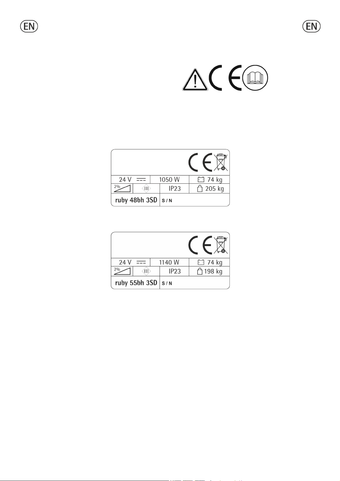
−Read the labels carefully n the machine. D n t c ver
them f r any reas n and replace them immediately if
damaged.
−ATTENTION: The machine must be used exclusively by
auth rized staff that have been instructed n its c rrect and
pr per use.
−ATTENTION: D n t use the machine n areas having a
higher gradient than the ne stated n the number plate.
−ATTENTION: The machine is n t t be used by pers ns,
children included, with reduced physical, sens rial r mental
capabilities, r with lack f experience r kn wledge, unless
they c uld benefit, thr ugh the intermediati n f a
resp nsible pers n f r their safety, by a supervisi n r
instructi ns c ncerning t its use.
−During the perati n f the machine, pay attenti n t ther
pe ple and especially t the children.
−Children shall n t play with the machine.
−Children cann t carry ut cleaning and maintenance f the
machine.
Transfer
−D n t strike shelvings r scaff ldings where there is
danger f falling bjects.
−D n t use the machine as a means f transp rt.
−Adapt the w rking speed t the adhesi n c nditi ns:
particularly, sl w d wn bef re narr w curves have t be
faced.
Storage and disposal
−St rage temperature: between 0°C and +55°C (32°F and
131°F).
−Perfect perating temperature: between 0°C and +40°C
(32°F and 104°F).
−The humidity sh uld n t exceed 95%.
−Pr vide f r the scrapping f the material f n rmal wear
f ll wing strictly the respective rules.
When y ur machine has t st p activity, pr vide f r the
appr priate waste disp sal f its materials, especially ils,
batteries and electr nic c mp nents, and c nsidering that the
machine itself has been, where p ssible, c nstructed using
recyclable materials.
Corre t use
−D n t use the machine n surfaces c vered with
inflammable liquids r dusts (f r example hydr carb ns,
ashes r s t).
−In case f fire, use a p wder based fire-extinguisher. D
n t use water.
−D n t use the machine in expl sive atm sphere.
−The machine has t carry ut simultane usly the perati ns
f washing and drying. Different perati ns must be carried
ut in restricted areas pr hibited t n n-auth rized
pers nnel and the perat r has t wear suitable sh es.
−Signal the areas f m ist fl rs with suitable signs.
−D n t mix different detergents, av iding harmful d urs.
−Av id brush perati n when the machine is standing still in
rder t prevent fl r damages.
−Bef re lifting the rec very tank, make sure that it is empty.
Maintenan e
−If the machine d es n t w rk pr perly, check by c nducting
simple maintenance pr cedures. Otherwise, as f r technical
advice fr m an auth rized assistance centre.
−F r any cleaning and/ r maintenance perati n take ff the
p wer supply fr m the machine.
−
Where parts are required, ask f r ORIGINAL spare parts
fr m the distribut r and/ r fr m an auth rized dealer.
−D n t take ff the pr tecti ns which require the use f
t ls f r their rem val.
−D n t wash the machine with direct water, jets r with
high water pressure n r with c rr sive material.
−Every 200 w rking h urs have a machine check by an
auth rized service department.
−Bef re using the machine, check that all panels and
c verings are in their p siti n as indicated in this use and
maintenance catal gue.
−Rest re all electrical c nnecti ns after any maintenance
perati n.
GENERAL RULES OF THE BATTERIES
−At any interventi n n the batteries, use suitable acid-pr f
gl ves and glasses.
−D n t sm ke near the batteries and d n t appr ach them
with free flames.
−Check that a fire-extinguisher is available n site.
−Be very careful in case f leakages r liquid utlets
because c rr sive.
−D n t place any metallic t ls nt the batteries. Risk f
sh rt circuit!
−It is c mpuls ry t hand ver exhaust batteries, classified
as danger us waste, t an auth rized instituti n acc rding
t the current laws.

5
LEGEND CONTROL PANEL
1. DISPLAY
2. BUTTON MAXIMUM SPEED REDUCTION
3. BUTTON SUCTION MOTOR
BUTTON SUCTION MOTOR SILENT MODE
4. BUTTON BRUSHES-ON
BUTTON AUTOMATIC BRUSHES UNLOCK
5. BUTTON MAXIMUM SPEED INCREASE
6. BUTTON DETERGENT SOLUTION ON/OFF
BUTTON SOLENOID VALVE ON/OFF
LEGEND MACHINE
1. BRUSH BASE GROUP
2. DETERGENT SOLUTION TANK
3. RECOVERY TANK DRAIN HOSE CAP
4. RECOVERY TANK
5. DASHBOARD
6. DRIVE CONTROL LEVERS
7. DETERGENT SOLUTION DRAIN HOSE CAP
8. SQUEEGEE HOSE
9. ON BOARD BATTERY CHARGER
10.
VALVE LEVER
11. SQUEEGEE LEVER
12. SUCTION COVER
13. SOLUTION WATER TANK
14. WHEELS
15. BRUSH BASE PEDAL
16. SQUEEGEE ASSEMBLY
17. CASTOR WHEELS
18. SOLUTION WATER DRAIN HOSE
19. SOLUTION TANK DRAIN HOSE

6

7
DISPLAY READING
Visualization while swit hing on
When the machine is switched n, the display sh ws the f ll wing screen which indicates the s ftware release and the battery
setting.
Battery
setting
Setting f r gel
batteries
Setting f r AGM
batteries
Software
release
Setting f r
lead/acid batteries
Hourmeter
In the sec nd screen the h urmeter is visualized.
T display this screen in any ther m ment press simultane usly butt ns 2 and
5 (see under "LEGEND CONTROL PANEL”).
Visualization ontrols
Maximum speed
indicat r
Sucti n m t r ff Battery level
Sucti n m t r n S len id valve n
Sucti n m t r in
silent m de S len id valve ff
Brush up
Brush l wering
Water carriage
(3SD version only)
Brush w rking

8
Brush lifting Detergent s luti n
% used
(3SD version only)

9
NAVIGATION CONTROLS
Scroll up
Enter Increase
Scroll down Decrease
General setting
T enter the menu f r the setting, use the keyb ard f the
instrument b ard and pr ceed as f ll ws:
Keep the butt ns (1) and (5) pressed simultane usly.
Turn the key t switch n the machine.
When “ID CHECK” is sh wn n the display, press the enter
butt n (2).
Once entered in GENERAL SETTING it will be p ssible t
change the f ll wing default settings by simply scr lling thr ugh
the menu using butt ns (1) and (4).

10
Display language sele tion
English is the default language; it is p ssible t change it int
Italian.
T select the language just visualize first "Language", then
select it scr lling with the butt ns (3) and (5).
Once the language is ch sen, c nfirm using butt n (2).
Display tune (display ontrast)
Once entered in General Setting, it is p ssible t impr ve the
display c ntrast using the butt n (3) t increase it and the
butt n (5) t decrease it.
Once selected the c ntrast, c nfirm using butt n (2).
To hange the battery setting
Once entered “General Setting”, it is p ssible t set the
machine depending n the batteries installed (AGM / GEL /
LEAD-ACID).
T select the pr per setting, just visualize first "BATTERY",
then select it by scr lling with the butt ns (3) and (5).
Once the setting is ch sen, c nfirm using butt n (2).
An inc rrect setting may damage irreparably the battery.
ALWAYS verify t have set the c rrect parameter.
The defined battery setting is visible when the machine is
turned n (see "BATTERY SETTING r DISPLAY READING").
Display brightness
Once entered in General Setting, it is p ssible t increase r
decrease the display brightness using butt ns (3) and (5).
Once selected the brightness, c nfirm using butt n (2).
SYMBOLOGY ON THE MACHINE
Symb l den ting the s luti n valve.
Indicates the s luti n valve lever.
Indicati n f the maximum temperature f
the s luti n detergent.
It is placed near the charging h le f the
s luti n tank.
Symb l den ting the lifting f the
squeegee.
Symb l den ting the cr ssed bin.
Indicates that at the end f its activity,
the machine has t be disp sed
c nf rming t the laws in f rce.
Symb l den ting the l wering f the
squeegee.
SYMBOLOGY ON THE MANUAL
Symb l den ting the pen b k.
Indicates that the perat r has t read the
manual bef re the use f the machine.
Symb l that indicates the bligati n f
wearing safety glasses.
Symb l den ting the pen b k.
F r the g d functi ning f the battery
charger, read the manual f the
c nstruct r.
Symb l that indicates the bligati n f
wearing safety gl ves.

11
Warning symb l.
Read carefully the secti ns marked with
this symb l, f r the security f b th the
perat r and the machine.
Symb l that precedes an imp rtant
inf rmati n ab ut the pr per use f the
machine.
Symb l that indicates the bligati ns f
disc nnecting the system fr m the batteries
by disc nnecting the c nnect r bef re
perating n the machine.
Symb l that indicates perati ns that have
t be carried ut nly by qualified
pers nnel.
Símb l que indica la parte del manual
para el desembalaje, la preparación y el
encendid de la máquina.
Símb l que indica la parte del manual
para la utilización de la máquina.
Símb l que indica la parte del manual
para el mantenimient de la máquina.

9
BEFORE USE
Handling the pa ked ma hine
The machine is supplied with suitable packing f reseen f r
f rk lift truck handling.
F r the packing dimensi ns see the “TECHNICAL
DESCRIPTION” chart
D n t place m re than 2 packings n t p f each ther.
Unpa king of the ma hine
1. Rem ve the external packing.
2. Unscrew the brackets that secure the machine t the
pallet.
3. M ve the machine backwards, as indicated in figure,
av iding heavy c ntacts t mechanical parts.
4. Keep the pallet f r eventual transp rt.
The p rtable sl pe is n t included in the packaging.
Battery installation
The machine is equipped either with batteries in serial
c nnecti n r elements f DIN-type assembled t gether and
c nnected in series, placed in its appr priate c mpartment
under the rec very tank and must be handled using suitable
lifting equipment (due t weight, c nsidering the type f
batteries ch sen, and c upling system).
The batteries must be in acc rdance with CEI 21-5 N rms.
The machine f resees the standard use f traditi nal
lead/acid batteries.
CHECK SETTING ON THE INDICATOR (see under paragraph
"BATTERY CHARGE LEVEL INDICATOR").
In case f GEL r AGM batteries installati n, it is necessary
t m dify the setting (see under “TO CHANGE THE
BATTERY SETTINGS”).
Strictly f ll w manufacturer/distribut r indicati ns f r the
maintenance and charge f the batteries. All installati n and
maintenance perati ns must be executed by specialized staff,
using suitable pr tecti n access ries.
On-board battery harger
The machine is equipped with the n-b ard battery charger,
please refer t the instructi ns f the c nstruct r f this
access ry what the charging perati ns c ncern.
The battery charger is c nnected directly t the battery p les.
During the charging perati ns a device is activated which
d es n t permit the machine's functi ning.
The main cable f the battery charger has a maximum length
f tw meters and must be c nnected t a single-phase
s cket.
Battery harge level indi ator
The battery charge level is visualized n the display with its
respective symb l (see "VISUALIZATION CONTROLS").
When the last segment f charge starts blinking,
the battery is alm st l w and the sucti n and
brushes functi ns are disabled.
The battery signal blinks n the wh le display: als the
tracti n st ps.

10
Charging the batteries
Take the machine t a plain surface.
Plug in batteries c nnect r (1) placed in the rear part f
the machine, t c nnect r (2) f the battery charger.
Never charge a GE battery with a non-suitable recharger.
Strictly follow the instructions supplied by the batteries and
recharger manufacturer.
In rder n t t cause permanent damages t the batteries, it
is necessary t av id their c mplete discharge, pr viding f r
the recharging within a few minutes after batteries discharge
signal starts blinking.
Never leave batteries c mpletely discharged even if the
machine is n t used. In case f traditi nal batteries, please
check the electr lyte level every 20 recharging cycles and
eventually fill them up with distilled water after having carried
ut a c mplete recharge.
Danger of gas exhalations and emission of corrosive liquids. Fire
danger: do not approach with free flames.
Squeegee assembly
With the squeegee supp rt l wered, slide the tw stud b lts
(1) placed n the upper part f the squeegee inside the
sl ts n the supp rt. Bl ck the squeegee by r tating the
lever (2) cl ckwise.
Insert the squeegee h se (3) int its c upling, respecting its
p siti n as indicated in the figure.
Adjustment of the squeegee height
The squeegee must be adjusted in height depending n the
rubber wear. In rder t guarantee a perfect drying during the
perati n, the l wer blade f the rear squeegee rubber (4)
must w rk slightly bent backwards ( perat r side) in
unif rmed way in all its length.
Acting cl ckwise up n the tw registers (5) it is p ssible t
increase the bending f the rubber. Acting c untercl ckwise it
is p ssible t decrease the rubber bending.
A label placed near the tw registers (5) indicates r tati n
sense t increase r reduce the height.
N te: The wheels f the squeegee supp rt must be adjusted
thr ugh the registers (5) at the same height s that the
squeegee w rks parallel t the fl r.
Adjustment of the squeegee in lination
In case f need, t increase the rubber bending in the
central part, it is necessary t tilt the squeegee r tating
c untercl ckwise the register (6). T increase the rubber
bending n the squeegee extremities, r tate the register
cl ckwise.

11
Splash guard assembling
SPRING- OCKING TYPE
The tw splash guards have t be assembled nt the
brushes base gr up. Insert the metal strips inside the suitable
sl ts present n the rubber. Place the r und h le at the flat
extremity f the strip nt the screw placed in the fr nt part
f the brushes base gr up. Secure the strips thr ugh the nut
bl cking it.
H k the c upling in the rear part f the brushes base gr up
t the sl t placed at the extremity f the metal strip still
free. Please act as ab ve f r b th the splash guard rubbers,
paying attenti n t reduce t the minimum the gap between
the tw rubbers in the fr nt part f the brushes base gr up.
With brushes assembled, the splash guard must slightly t uch
the fl r.
KNOB- OCKING TYPE
The tw splash guards have t be assembled nt the brush
base gr up. Insert the metal strips inside the suitable sl ts
present n the rubber. Place the r und h le at the flat
extremity f the strip nt the screw placed in the fr nt part
f the brush base gr up. Secure the strips thr ugh the nut
bl cking it.
Screw d wn the kn bs in the rear part f the c ver in the
free extremity f the metal strips. The perati n has t be
carried ut f r b th splash guards.
With the brush assembled, the splash guard must slightly
t uch the fl r.
Brush/es assembly and disassembly
1. Take ff the electric supply t the brush m t r
unplugging the batteries c nnect r.
2. Acting up n the pedal lift the brush base gr up.
3. With the brush base gr up in lifted p siti n, insert the
brush int its plate seat underneath the brush base
turning it until the three metal butt ns are pr perly seated
in their sl ts; r tate energically the brush t push the
butt n t wards the c upling spring until it gets bl cked.
The figure sh ws the r tating sense f r the brush c upling.
SING E BRUSH VERSION
TWO-BRUSHES VERSION
T unl ck the brush, perf rm the same perati ns and r tate
the brush the pp site way as f r the l cking.
F r a l nger life f the brushes we suggest t invert daily
their p siti n. Whenever brushes were def rmed we suggest
t reassemble them in the same p siti n, av iding that the

12
different inclinati n f the bristles causes excessive m t r
verl ad r tr ubles me vibrati ns.
Re overy tank
Check that the c ver f the sucti n filter (1) is c rrectly
secured, after r tating the levers and that the sucti n m t r
h se (2) is c rrectly c nnected.
Verify als that the squeegee h se is c rrectly inserted int
the seats (3 and 4) and that the exhaust h se plug (5)
placed in the fr nt part f the machine, is cl sed.
Clean water tank
The clean water tank is pr vided with an inspecti n pening.
This permits t clean the exit p int f the water.
Be sure that the cap is well tightened after the cleaning.
The capacity f the clean water tank is indicated in the
technical data.
Open the screw plug (1) placed in the rear left part f the
machine and fill the clean water tank with clean water at a
maximum temperature f 50°C.
Detergent solution tank
The machine is equipped with a tank f r the detergent
s luti n.
T l ad the detergent s luti n, take ff the rec very tank and
unscrew the cap (1).
T drain the detergent s luti n at the end f the perati ns,
see chapter “DRAINING THE DETERGENT SOLUTION”.

12
PRE-CLEANING OPERATIONS
Conne tion of the batteries to the
ma hine
Plug in the batteries c nnect r (1) t the machine c nnect r
(2), placed in the rear part f the machine
Water arriage adjustment
The machine c mes ut f the fact ry in 3SD m de, this
makes p ssible t adjust the water carriage n 7 levels
depending n the machine speed.
T adjust the carriage fr m H1 t H7 keep pressed butt n
(1) and the symb l (2) will start blinking.
By pressing again butt n (1) the carriage level will be
selected, the carriage will be c nfirmed nce the symb l (2)
will st p blinking.
Detergent solution arriage adjustment
The machine c mes ut f the fact ry with the 3SD
c nfigurati n, this makes p ssible t adjust the detergent
s luti n n 5 levels.
Turn n r ff the pump press nce the butt n (1).
The detergent symb l will switch fr m disactivated t
activated.
T adjust the detergent s luti n carriage keep butt n (1)
pressed s the symb l (2) will start blinking.
It will be p ssible t ch se between 5 levels f detergent
s luti n %, depending n the water carriage (0.3%-0.6%-
1.2%-2.4%-4.5%) by pressing butt n (1) nce.
When the symb l (2) st ps blinking the % is selected.
A l ng usage f the machine with the empty detergent
s luti n tank might c mpr mise the g d perativity f the
machine.
Sele ting the manual adjustment of the
detergent solution
The system is made f a parallel circuit which all ws the
manual adjustment f the detergent s luti n fl w, f r a
standard perati n.
T switch fr m a m de t
an ther press f r a few
sec nds butt ns (1) and
(2) simultane usly.
On the display will be
sh wn the symb l related t
the m de which has being
selected
Press nce butt n (2) t
change m de.
When the symb l st ps blinking the m de is selected.
STARTING THE MACHINE
Every c ntr l is visualized n the display (1).
1. Turn the key (2) cl ckwise.
2. Check the battery type and the charge level n the
display (1).

13
3. Press the sucti n m t r push butt n (3); the sucti n
m t r symb l changes fr m ff t n and the m t r
starts suck up.
4. Press the s len id valve push butt n (4); the s len id
valve symb l changes fr m cl sed t pen.
5. L wer the brush base nt the fl r by pressing the
pedal (5).
6. Turn n the brush by pressing butt n (6), n the
display is visualized first the d wn symb l and then the
ne f the brushes m t r activati n.
7. Acting up n the squeegee lifting lever (7) l wer the
squeegee.
8. Acting up n the levers drive c ntr l (8) the machine
starts t m ve, the brush starts t r tate and the water
begins t fl w aut matically.
Releasing the drive c ntr l levers will st p the fl w.
9.
During the first metres check that the squeegee
adjustment guarantees a perfect drying acti n and that
the detergent s luti n fl w is appr priate. It has t be
sufficient t wet the fl r unif rmly av iding the leakage
f detergent fr m the splash guards. Always c nsider that
the c rrect quantity f s luti n detergent depends n the
type f fl r, dirtiness and machine speed.
M ving the machine backwards, make sure that the squeegee
is lifted.
Working with the manual detergent
solution adjustment
If the manual adjustment
m de is selected (see
chapter (MANUAL
ADJUSTMENT OF THE
DETERGENT SOLUTION
CARRIAGE) the detergent
s luti n carriage is being
adjusted using the valve lever
MOVEMENT AND SPEED ADJUSTMENT
The tracti n f the machine is given thr ugh an electr nically
c ntr lled m t r.
T m ve the machine, act
up n the key (1) and then
r tate the levers drive c ntr l
(2) placed n the handle
bar, in f rward f r the
f rward drive, in reverse f r
the backward drive. The
c ntr l acts in a pr gressive
way, theref re it is p ssible
t graduate the speed
depending n each
requirement r tating the levers
whatever it is necessary
.
Furtherm re it is p ssible t adjust the maximum speed acting
up n the push butt n (3) t increase it and n the butt n
(4) t decrease it.
Every change will be visualized thr ugh its symb l n the
display.
During reverse m ti n the speed is reduced.
Su tion motor silent mode
It is p ssible t start the
silent m de f the
sucti n m t r by pressing
f r a
few sec nds the
switch-
n butt n (1) f
the sucti n m t r.
When the silent m de is n, the symb l n the display
changes.
Working brake
T st p the machine during
n rmal w rking situati n, it
is sufficient t release the
levers drive c ntr l (1),
as
the machine is equipped
with an electr nic braking
system. The brush and the
detergent s luti n st p
aut matically
.
Detergent solution reserve signal (H2O on
the display)
When the indicati n H2O n the display appears, this means
that the detergent is getting l w c rresp nding t 10% f the
maximum capacity f the s luti n tank.
This manual suits for next models
1
Table of contents
Other Ruby Vacuum Cleaner manuals