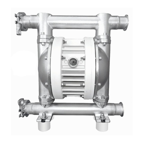
Ruby Black Line Ruby 120 Manual

Air Operated Diaphragm Pumps
Installation, Operation and
Maintenance
Installation, Operation and Maintenance
Ruby 120 Non Metallic

INDEX
1.0 Introduction.................................................................................................................... 1
1.0.1 Pump Identification...................................................................................................... 2
1.0.2 Markings and general information................................................................................ 3
1.0.3 Composition Codes ...................................................................................................... 3
1.1 Warranty ........................................................................................................................ 4
1.2 Transport, unipacking, storage........................................................................................ 5
1.3 Principle of function........................................................................................................ 5
1.4 Pump operation.............................................................................................................. 6
1.5 Improper use .................................................................................................................. 6
2.0 Safety Rules.................................................................................................................... 7
2.1 Equipotential bonding / earthing....................................................................................11
3.0 Installation.....................................................................................................................12
3.1 Connection of air supply line..........................................................................................13
3.2 Connection of cuction and pressure lines .......................................................................14
3.3 Pump in suction operation .............................................................................................14
3.4 Pump in submerged operation.......................................................................................14
3.5 Connecting to the product circuit...................................................................................14
3.6 Noise emissions (2003/10/EC)........................................................................................15
3.7 Temperature range of the diaphragm material...............................................................16
3.8 Temperature range of the Housing material...................................................................16
4.0 Troubleshooting.............................................................................................................17
5.0 Technical Data ...............................................................................................................18
5.1 Dimensional Drawings....................................................................................................18
5.2 Performance..................................................................................................................19
5.3 Exploded View ...............................................................................................................22


1

1
ATEX Pumps - Conditions For Safe Use
1.Ambient temperature range is as specified in page 16.
2.ATEX compliant pumps are suitable for use in explosive atmospheres when the equipment is
properly grounded in accordance with local electrical codes
3.
Conductive Polypropylene, conductive Acetal or conductive PVDF pumps are not to be installed
in applications where the pumps may be subjected to oil, greases and hydraulic liquids.
4.
Ruby 010 3/8’’ shall not be installed in applications and areas with hydrogen and acetylene
atmosphere.
5.
When operating pumps equipped with non-conductive diaphragms that exceed the maximum
permissible projected area, as defined in EN ISO 80079-36 : 2016 section 6.7.5 table 8, the following
protection methods must be applied:
-Equipment is always used to transfer electrically conductive fluids or
-Explosive environment is prevented from entering the internal portions of the pump, i.e. dry
running.
1.0 Introduction
Ruby pumps have been manufactured to the 2006/42/EC, 2014/34/EU directives. The relevant
area criteria are indicated in the EN-60079-0:2018 , EN-12100:2010 , EN-809:1998+A1:2009 , EN-
80079-36:2016, EN-80079-37:2016, EN-80079-38:2016 harmonized European standards.
Therefore, if used according to the instructions contained in this manual, the Ruby pumps will not
represent any risk to the operator. This manual must be preserved in good condition and/or
accompany the machine as reference for maintenance purposes. The manufacturer rejects any
liability for any alteration ,modification, incorrect application or operation not complying with the
content of this manual and that may cause damage to the health and safety of persons, animals or
objects stationing near the pumps. The following instructions solely refer to Ruby Air Operated
Diaphragm Pumps. Since the pumps are used in combination with other assemblies, such as
solenoid valves, sensors or pulsation dampers, the valid operating instructions for these
components and the associated notes on safety must also be taken into account. These
instructions contain information on safety, installation, operation, maintenance, repair and
environmental waste disposal of the Ruby Air Operated Diaphragm Pump. Thoroughly read these
instructions before use and always follow the information contained therein. Persons entrusted
with the installation, operation, maintenance or repair of the pump must have read and
understood these instructions, especially the chapter on “Health and Safety”. This applies in

2
particular for those who are only occasionally involved in work on the pump, like cleaning or service
personnel. Each pump is subjected to stringent inspections and function tests before leaving the
factory.
You should always bear in mind that a correct function, a long lifetime and optimal operational
reliability of the pump mainly depend on :
correct installation
correct commissioning
and correctly performed maintenance and repair work.
Enquiries concerning service, spare parts or repairs should be addressed to the manufacturer
Always provide the following information:
series
pump size
serial number of pump
This information is stamped on the identification plate on top of the pump.
Danger!
When returning pumps or pump parts to your supplier for repair or general overhaul, the delivery
must be accompanied by certificates stating that pumps or pump parts are free of product and
other aggressive or hazardous substances.
1.0.1 Pump Identification
Each pump has an identification plate carrying its specification details and materials.
Always refer to this data when contacting the manufacturer, dealer or customer service centers.
WARNING: removing or altering this identification plate and or the data it contains is
forbidden. Identification code on the plate against the “TYPE” heading specifies the composition
and the materials used to build the pump. This data will help ascertain whether the pump is
suitable for the product to be pumped.

3
1.0.2 Markings and general information
In compliance with the 2014/34/EU standards, the Ruby pumps carry the following identification
marks:
EU Directive 2014/34/EU Equipment and protective systems intended for use in potentially
explosive atmospheres (ATEX)
EN ISO 80079-36 :2016 Non electrical equipment for use in potentially explosive atmospheres -
Basic method and requirements
EN ISO 80079-37:2016 Non electrical equipment for explosive atmospheres –No electrical type
of protection by constructional safety '' c '' , control of ignition source “b” , liquid immersion “k”
EN ISO 80079-38:2016 Equipment and components in explosive atmospheres in underground
mines
Machinery Safety Directive: 2006/42/EC
IEC 60079-0 :2018 Explosive atmospheres - Equipment General requirements
CLC/TR 60079-32-1 :2018 Explosive atmospheres- Electrostatic hazards, guidance
For Zone 1: II 2/2 G Ex h IIC T4 Gb
II 2/2 D Ex h IIC T35 Db
For Zone 2: II 3G Ex h IIB T4 Gc
II 3G Ex h IIIB 135c Dc
1.0.3 Composition Codes
Ruby Pumps composition codes

4
1.1 Warranty
The correct function of each Ruby pump is tested in the factory.
However, should any defect appear, please contact the Manufacturer’s After-Sales Service, your
dealer or the nearest Customer Service Centre where you will receive assistance as quickly as
possible. In any case, please provide:
Α- Your complete address B- Pump identification
C- Explosion risk protection class
D- Anomaly description
All Ruby pumps are covered by the following warranty:
Five years for any faulty mechanical parts. The warranty period starts from the date of supply.
Any fault or anomaly must be reported to the Manufacturer within eight days.
Warranty repair will be carried out exclusively at the Manufacturer's premises. Transportation
charges will be at the client's expense.
Warranty shall not be extended in case of repair or replacement.
Faulty parts must be forwarded to the Manufacturer who reserves the right to test them in this
own factory to identify the fault or any external reason that may have caused it. Should the parts
be found not faulty, the Manufacturer reserves the right to invoice the total cost of the parts that
had been replaced under this warranty.
Costs and transportation risks of faulty, repaired or replaced parts including custom charges will
be borne entirely by the client. Repair or replacement of faulty parts cover any obligation under
this warranty.
The warranty DOES NOT cover any indirect damage and in particular any normal consumable
material such as diaphragms, ball seats, balls and others.
The warranty does not cover parts damaged as a consequence of incorrect installation,
carelessness, neglect, incorrect maintenance, or damages due to transportation or to any other
reason or event that is not directly linked to functional or manufacturing defects.
The warranty excludes all cases of improper use of the pump or incorrect applications or non-
observance of the information contained in this manual.
Any controversy falls within the jurisdiction of the Court of Athens.

5
1.2 Transport, unipacking, storage
In order to avoid any problems you should check the delivered goods against the delivery note for
completeness and correctness. Be careful when unpacking the pump and proceed as follows:
Check the packaging material for transport damage.
Take the pump carefully out of the packaging material.
Check the pump for visual damage.
Remove the plugs from all pump ports.
Check seals and fluid lines for damage.
The following points must be strictly observed when preparing the pump for storage:
Store the pump in a dry place.
Thoroughly clean used pumps before storage.
Do not subject stored pumps to extreme temperature fluctuations.
1.3 Principle of function
No.
Description
1.
Discharge manifold
2.
Top valve ball (closed during suction)
3.
Diaphragm
4.
Pump chamber
5.
Bottom valve ball (opened. Medium flows into
chamber)
6.
Top valve ball (open. Product is pressed out)
7.
Center Block (the drive air displaces the medium
via the diaphragm and at the same time pulls back
the second diaphragm)
8.
Bottom valve ball (closed during delivery)
9.
Suction manifold
10.
Air control unit
11.
Air valve drive

6
1.4 Pump operation
Ruby Air Operated Diaphragm Pumps are oscillating positive displacement pumps with two pump
chambers arranged opposite each other. Both of these are separated by a diaphragm each into an
air and a fluid section.
Both diaphragms are linked by a piston rod, so that with every stroke product is displaced to the
outside from the one pump chamber and product is drawn into the opposite pump chamber.
1.5 Improper use
Particularly, it is FORBIDDEN to use Ruby pumps for :
production of vacuum;
operation as an on -off valve, as a non-return valve or as a metering valve
operation with liquid that is chemically incompatible, with the materials of construction;
operation with suspended products whose specific weight is higher than the liquid's (for example
with water and sand).
With air pressures, temperatures or product characteristics that do not comply with the pump's
technical data.
WARNING: since an endless variety of products and chemical compositions exist, the user is
presumed to have the best knowledge of their reaction and compatibility with the pump's
construction materials. Therefore, before using the pump. all necessary checks and tests must
be performed with great care to avoid even the slightest risk, an event that the manufacturer
cannot foresee and for which he cannot be held responsible.
WARNING: the user must consider the ratio between the pump’s maximum surface
temperature indicated on the marking and the minimum ignition temperature of the layers and
clouds of powder as shown in the ΕΝ1227-1.
WARNING: Use of the pump that does not comply with the instructions indicated in the use
and maintenance manual will cancel the safety and explosion protection requirements. The risks
associated with use of the pumps under the exact conditions set forth in the use and
maintenance manual have been analyzed, whilst the analysis of the risks associated with the
interface with other system components must be carried out by the installer
The user is responsible for classifying the area of use whilst identification of the equipment
category is the responsibility of the manufacturer.

7
2.0 Safety Rules
Dangerous or hazardous practices or practice not complying with the safety rules and with the
recommendations contained herein, may cause serious injuries, material damage and even
explosions and /or death for which the manufacturer cannot be held responsible.
WARNING: these instructions are essential for the pumps' compliance to the requirements of
the 2006/42/EC directive and must therefore be available, known, understood and applied.
WARNING: the personnel in charge of installing, inspecting and servicing the pumps must
have suitable technical knowledge and training in matters concerning potentially explosive
atmospheres and the related risks
WARNING: use of the pumps in a manner that does not comply with the instructions
indicated in the use and maintenance manυaI will cancel all the requirements for safety and
protection against of explosions.
WARNING: before intervening on the pump and/or servicing or repairing it, please- note that
you must:
A - Discharge any product that was being pumped
B - Wash it internally using a suitable non-flammable fluid, then drain.
C - Cut-off the air supply using the relevant valve and make sure that no residual pressure
remains inside it. D - Close all on-off valves {delivery and intake sides) relative to the product.
Ε - Disconnect the network air supply;
F - Wear suitable individual protection before any maintenance or repair (goggles / face
protection, gloves, closed shoes, aprons and others).
WARNING: before using the pump, make sure that the fluid to be pumped is compatible with
the explosion protection class and with construction materials of the pump.
DANGER OF CORROSION, PRODUCT SPILLS AND/ OR EXPLOSIONS CAUSED BY CHEMICAL REACTIONS
For installation and use in a potentially explosive environment, comply with these general
precautions
ascertain that the pump is full and if possible, that the level is above it by 0.5 m;
ascertain that the fluid treated does not contain or cannot contain large solids or solids of a
dangerous shape.
ensure that the intake or delivery ports are not obstructed nor limited to avoid cavitation or
pneumatic motor strain.

8
also ascertain that the connection piping is strong enough and cannot be deformed by the pump
weight or by the intake. Also check hat the pump is not burdened by the weight of the piping.
If the pump is to stay in disuse for a long period of time, clean it carefully by running a non-
flammable liquid detergent through it that is compatible with the pump's construction materials.
if the pump was turned off for a long period of time, circulate clean water it in for some minutes
to avoid incrustations.
before starting, after long periods of disuse, clean the Internal and external surfaces with a damp
cloth;
check the grounding;
always protect the pump against possible collisions caused by moving objects or by various blunt
materials that may damage it or react with its materials;
protect the pump's surrounding ambient from splashes caused by accidental pump failure;
if the diaphragms are completely torn, the fluid may enter the air circuit, damaging it, and be
discharged from the exhaust port. It is therefore necessary for the exhaust port to be conveyed by
pipes to a safe area.
WARNING: the air supply pressure must never be over 8 bar or below 2 bar.
WARNING: when using the pump with aggressive or toxic liquids or with liquids that may
represent a health hazard you must install suitable protection on the pump to contain, collect
and signal any spills: DANGER OF POLLUTION, CONTAMINATION, INJURIES AND/OR DEATH.
WARNING: the pump must not be used with fluids that arc not compatible with its
construction materials or in a place containing incompatible fluids.
WARNING: installing the pumps without on off valves on the intake and delivery sides to
intercept the product in case of spillage is forbidden: danger of uncontrolled product spillage.
WARNING: installing the pumps without on-off. three way or check valves on the air supply
piping to prevent the pumped liquid from entering the pneumatic circuit if the diaphragms are
broken is forbidden: danger of fluid entering the compressed air circuit and being discharged
into the environment.
WARNING: Should the user think that the temperature limits set forth in this manual may be
exceeded during service, a protective device must be installed on the system to prevent the
maximum allowed process temperature from being reached.
If exceeded, respect of the maximum temperature marked cannot be guaranteed.

9
WARNING: The pumps must always be grounded irrespective of any organ to which they are
connected. Lack of grounding or incorrect grounding will cancel the requirements for safety and
protection against the risk of explosion.
WARNING: the use of pumps made with non-conductive material, which become charged
with static, and without suitable grounding for flammable liquids is forbidden: RISK OF
EXPLOSIONS DUE TO STATIC CHARGE.
WARNING: Aggressive, toxic or dangerous liquids may cause serious injuries or damage to
health, therefore it is forbidden to return a pump containing such products to the manufacturer
or to a service center. You must empty the internal circuits from the product first and wash and
treat it.
WARNING: Pumps containing aluminum parts or components coming into contact with the
product cannot be used to pump.
Ill-trichloroethane, methylene chloride or solvents based on other halogenated hydrocarbons:
DANGER OF AN EXPLOSION CAUSED BY A CHEMICAL REACTION.
WARNING: Conductive Polypropylene, conductive PVDF pumps are not to be installed in
applications where the pumps may be subjected to oil, greases and hydraulic liquids.
WARNING: The components of the pneumatic exchanger, including the shaft are made from
materials that are not specifically resistant to chemical products, if the diaphragm should break,
replace these elements completely if they have come into contact with the product.
WARNING: The air-driven motor of the Ruby pumps is self-lubricating and will not require
any greasing. Therefore a void using Iubricated and non- dried air.
WARNING: ascertain that during service no anomalous noise appears. In that case, stop the
pump immediately.
WARNING: ascertain that the fluid at the delivery side does not contain gas. Otherwise stop the
pump immediately.

10
WARNING: Periodic controls must be made to ensure that there is no powder and/or
deposits on the external and internal.
surfaces of the pump and, if necessary, they must be cleaned with a damp cloth
WARNING: removal of the silencer and the air supply fitting must be done when free from
powder. Before restarting the pump, ensure that no powder has entered the pneumatic
distributor.
To replace worn parts, use only original spare parts.
Failure to comply with the above may give rise to risks for the operator, the technicians, the
persons, the pump and/or the environment that cannot be ascribed to the manufacturer.
WARNING: diaphragm pumps with negative suction are affected by the following factors:
-viscosity and specific weight of the fluid;
-suction diameter and length.
Position the pump as close as possible to the point of collection {within 2.5 m.) and in any case
never more than 5 m. The diameter of the intake pipe must never be smaller than the connection
of the pump, but must be increased as the distance increases. Fluid to be pumped with negative
suction must never exceed a viscosity of 5.000 cps at 20° C and a specific weight of 1.4 Kg/I. These
elements can cause derating and reduce the duration of the diaphragm: DANGER OF
PREMATURE BREAKAGE.

11
2.1 Equipotential bonding / earthing
In principle, pumps and accessories must be earthed or provided with equipotential bonding if
there is the possibility of product specific electro-static charging and when used in potentially
explosive areas. Pumps and pulsation dampers with ATEX II 2/2 G Ex h IIC T4 Gb –II 2/2 D Ex h IIC
T35 Db approval are therefore fitted with an earthing screw.
Please Pay attention
For Zone 1
Aluminum in combination with stainless steel (greater or equal 16,5% Cr) is only be used if the
steel cannot corrode and no iron oxide and/or rusty particles can be deposited on the surface.
(appropriate reference to the properties of the stainless steel shall be given in the technical
documentation and instruction for use.
For Pumps with diaphragm type TFM:
1.Not run empty with flammable fluid/gas.
2.Flush before
For Zone 2
1.Not run empty with flammable fluid / gas.
2.Flush before
WARNING: the use of pumps made with non-conductive material, which become charged
with static, and without suitable grounding for flammable liquids is forbidden:
RISK OF EXPLOSIONS DUE TO STATIC CHARGE

12
3.0 Installation
To be observed before installation
1.The installation must only be carried out by persons who have the necessary skills for this work.
2.Before installation align the pump correctly and fasten it without any tension. Pipelines must be
assembled in a way that the basic weight of the lines is not reasting on the pump.
3.In order to avoid damage to the pump new installations should generally be checked for any
debris (welding beads, pieces of wire, etc.) in tank and pipeline system.
4.Consider the arrangement of the pump with respect to suction and discharge heads.
5.The pump system must be designed according to the requirements of the application. Valves or
spools must be installed as close as possible to pressure port. This also applies for T-fittings with
valve for bypass control or pressure relief valves, pressure gauges, flow control valves and shut-off
valves.
6.Thoroughly examine the alignment of the pump with the pipelines, in order to avoid strain and
premature wear.
7.Check all pipelines for leaks. This applies in particular for the suction line, in order to avoid the
intake of air.
8.If the fluid to be pumped contains solid particles bigger than specified , a filter must be installed.
The filter must be of such a size, that the change in resistance at the pump inlet port is only minor.
This filter must be permanently monitored and, if necessary, cleaned.
9.Fluids which change their viscosity must be permanently agitated, or the tank must be fitted with
a temperature sensor. With increasing viscosity start the agitator and/or the heating. This is of
special importance for intermittent operation!
Note: It is recommended to install flexible, shape and pressure resistant hoses or compensators
at the suction and pressure ports of the pump. This will prevent the transfer of pulsation shocks
into the pump.

13
3.1 Connection of air supply line
We recommend to supply the air through a hose to the pump. Using moisturized compressed air
requires the installation of a service unit with water separator. This control equipment can
additionally be used to regulate the flow capacity of the pump. The diaphragm must not be
subjected to shock loads. For this reason we recommend the installation of a spool, diaphragm or
needle valve as shut-off element.
WARNING: pneumatic supply to the Ruby pumps must he made using FILTERED. DRIED. NON
LUBRICATED OIL FREE AIR at a pressure of not less than 2 bars and not more than 8 bars.
WARNING: do not remove RESET for any reason and/or do not connect the air supply to the
RESET channel Warning! Do not use a ball valve as shut-off element.
Note: Especially for plastic pumps or pumps with PTFE diaphragms it is highly recommended to
install a slow start valve in the supply line to the pump. This valve protects both the diaphragm
and housing parts against suddenly occurring pressure shocks
.

14
3.2 Connection of suction and pressure lines
Suction and pressure lines must be installed in a way that no additionally loads are applied to the
pump ports.
The tightening torque of the mounting screws and the pressure strength of the sockets and flanges
must be observed with the installation of the suction and pressure lines. After assembly check the
system for leaks.
3.3 Pump in suction operation
Ruby Air Operated Diaphragm Pumps are dry self-priming. Depending on the pump design a
suction head of max. 9 mwc can be reached, when the suction line is filled.
3.4 Pump in submerged operation
The Ruby Air Operated Diaphragm Pumps are suitable for submerged operation. However, it must
be assured that the surrounding fluid will not attack the pump.
When installing the pump make sure that the air discharge muffler has been removed and the
exhaust air is discharged from the fluid through a hose.
3.5 Connecting to the product circuit
After positioning the pump you can now connect it to the product circuit as follows:
WARNING: only fittings with cylindrical gas threads in materials compatible with both the
fluid to be pumped and the pump’s construction materials must be used.
For example:
Pump made from PP - PP fitting.
Stainless steel pump = stainless steel fitting.
1.On the suction and discharge manifold install a manual valve of the same diameter as the pump
inlet (never smaller) to intercept the fluid correctly in case of spills and / or when servicing the
pump.
2.Install the sleeves to secure the flexible hoses on both valves.

15
WARNING: the pump must be connected with FLEXIBLE HOSES REINFORCED WITH A RIGID
SPIRAL of a diameter never smaller than the pump's connection. The filters or other equipment
installed at the intake side must be suitably dimensioned in οrder to avoid pressure drops. For
negative installations and/or viscous fluids, use hoses with an OVERSIZE DIAMETER, especially
on the intake side. Connections using rigid pipes may cause strong vibrations and break the
manifolds.
3.Connect the product intake and delivery hoses to their respective fittings whilst taking into
consideration the signs on the pump:
IΝ" = INTAKE (down) and
OUT" = DELIVERY (up)
or according to that indicated by the arrows.
4.Secure the hoses using the relevant clamps
WARNING: Provide appropriate support for the piping. THE PIPING MUST BE STRONG
ENOUGH TO AVOID DEFORMATION DURING THE SUCTION PHASE AND MUST NEVER WEIGH
DOWN ON THE PUMP IN ANY WAY OR VICE VERSA.
5.If used for drum suction (not below head), the submersed end of the intake hose must be
provided with a diagonally cut fixing to prevent it from adhering to the drum bottom.
WARNING: Ascertain that the fluid treated does not contain or cannot contain large solids or
solids of a dangerous shape and that the intake or delivery ports are not obstructed nor limited
to avoid either cavitation or pneumatic motor strain.
Connection off the product circuit finishes here.
3.6 Noise emissions (2003/10/EC)
In a room with several pumps you may experience an extreme development of noise . Depending
on the sound pressure level the following measures must therefore be applied:
Below 70 dB (A) : No special measures required
Above 70 dB (A) : Persons who are permanently in the room must wear ear defenders.
Above 85 dB (A : Room with dangerous noise level.! Each door must have a clearly noticeable
waning sign to warn persons from entering the room without ear defenders.

16
3.7 Temperature range of the diaphragm material
TFM Compound Diaphragm
-10o C - 130o C
NBR Conductive Diaphragm
-10o C - 100o C
TFM Full capacity Compound Diaphragm
-10o C - 130o C
EPDM Conductive Diaphragm
-10o C - 100oC
VITON Conductive diaphragm
-40o C - 170o C
3.8 Temperature range of the Housing material
Stainless steel
-25oC - 130o C
Aluminium
-10o C - 130o C
Polypropylene
0oC - 60oC
PVDF + CF
-10oC - 120oC
Table of contents
Other Ruby Water Pump manuals
Popular Water Pump manuals by other brands

Dover
Dover PSG WILDEN HS430S manual

Pfeiffer Vacuum
Pfeiffer Vacuum HiPace 2300 operating instructions

Bomba Elias
Bomba Elias BF Series Installation and assembly

Edson
Edson 165AL-30 Operations & parts manual

Grundfos
Grundfos Unilift KP 150 Installation and operating instructions

B+BTec
B+BTec VAC 800 Translation of the original instructions

Ambu
Ambu Res-Cue Pump Directions for use

Enerpac
Enerpac XC Series instruction sheet

Gator Prime
Gator Prime GP Series Installation, operation, and maintenance manual with parts list

Lotus
Lotus Diamond 750 Installaltion & maintenance manual

EHEIM
EHEIM 1260 manual

Drummond
Drummond 63317 Owner's manual & safety instructions