Ruckus Wireless SC8800-S User manual

Copyright © 2013 Ruckus Wireless, Inc. Page 1 of 4
Published November 2013, Part Number 800-70486-001 Rev A
SC8800-S Media Converter
Kit
Quick Setup Guide
This Quick Setup Guide provides step-by-step
instructions for installing a Media Converter Kit in a
Ruckus WirelessTM ZoneFlex™ SmartCell™ SC8800-S
Outdoor Access Point.
BEFORE YOU BEGIN
Before deploying your Ruckus Wireless device, please
check the Ruckus Wireless Web site for the latest
software and release documentation.
• Release Notes and User Guides are available at
http://support.ruckuswireless.com/documents
• Software Upgrades are available at
http://support.ruckuswireless.com/software
• Open Source information is available at
http://support.ruckuswireless.com/open_source
PACKAGE CONTENTS
• One Media Converter Assembly
• Four 4" (100mm) nylon cable ties
• Two locking wire saddles, with arrowhead
• One M25 cable gland
• M25-to-5/8" thread adapter and O-ring, for use with
optional customer-supplied FOTC (fiber optic trunk
cable)
•ThisQuick Setup Guide
RELATED PARTS
The media converter requires one of the following small
form-factor pluggable (SFP) transceivers as an interface
to the customer-supplied fiber-optic cable.
• Single-Mode EPON SFP Optic Module Kit
(P/N 902-0202-0000)
• Single-Mode 1000Base-LX SFP Optic Module Kit)
(P/N 902-0203-0000)
REQUIRED TOOLS AND SUPPLIES
• Phillips screwdrivers
• Wide flat-blade screwdriver
• Security Torx T30 bit
• 27mm hex socket
• Ratchet wrench
•Torquewrench
• Torque screwdriver with assorted bits
• Cable tie cutter
OPTIONAL SUPPLIES
• Customer-supplied FOTC (fiber optic trunk cable),
including strain relief connector and fitting nut
• Customer-supplied FOTC heat-shrink tubing
STEP 1: INSTALLING THE LOCKING WIRE SADDLES
A. Lay the SC8800-S on its back on a flat surface, and
open the front cover.
B. Snap the two locking wire saddles into the interface
circuit board inside the FIBER port.
WARNINGS!
This is a Class 1 laser product.
The laser radiates when the system is open and the
interlocks are bypassed.
Ruckus Wireless products must be installed, serviced and
replaced by a professional installer.
CAUTION!
This procedure assumes that the SC8800-S is being
modified before it is mounted on a pole. After the
SC8800-S is mounted on a pole, this procedure becomes
much more difficult.
WARNING!
A short-circuit backup protection device must be
connected to AC-powered equipment according to local
or national electrical codes.
Cable
management
plate
Locking
wire saddles
(2 places)
Interface circuit board

Copyright © 2013 Ruckus Wireless, Inc. Page 2 of 4
Published November 2013, Part Number 800-70486-001 Rev A
STEP 2: INSTALLING THE MEDIA CONVERTER
A. Cut and remove the cable tie fastening the media
converter power cable to the cable management
plate.
B. Move the media converter power cable, and plug the
power connector into the media converter before you
install the media converter.
C. Use the four captive screws to install the media
converter in the SC8800-S chassis. Tighten the screws
to 0.8 N.m (7 in-lbs).
STEP 3: INSTALLING THE SFP TRANSCEIVER
Use the ESD-prevention wrist strap or other grounding
device to an ESD ground or to bare metal on the Ruckus
Wireless equipment.
A. Remove the separately-ordered SFP transceiver from
its package. Refer to Related Parts for available SFP
transceivers.
B. Gently insert the SFP module into the FIBER port of
the media converter until it clicks into place.
C. Verify that the SFP module is correctly installed by
gently pulling on the SFP module without releasing
the latch.
When the SFP module cannot be removed, it is cor-
rectly installed.
D. If the SFP module can be removed, then install it
again and use slightly more force to press it into its
slot. If necessary, repeat until the SFP module is firmly
secured into its socket.
To remove the SFP module, pull on its latch.
STEP 4: UNPLUGGING THE ETHERNET CABLE
FROM THE INTERFACE CIRCUIT BOARD
A. Unplug the Ethernet cable from the interface circuit
board, and move it out of the way. If necessary,
untwist or cut the 1 or more cable ties indicated in the
figure.
B. Continue with Step 5: Plugging the Ethernet Cable
into the Media Converter.
CAUTION!
BE CAREFUL not to damage the external antenna feed
cables.
Media
converter
Plug in
power
connector
Cut cable tie here
Move power
connector
NOTE:
Do not remove the optical plugs until later in this
procedure.
Media
converter
SFP transceiver
Insert
this way
CAUTION!
Do not cut or damage the cables.
Unplug the Ethernet
cable from here
Cut cable tie(s) here,
if necessary

Copyright © 2013 Ruckus Wireless, Inc. Page 3 of 4
Published November 2013, Part Number 800-70486-001 Rev A
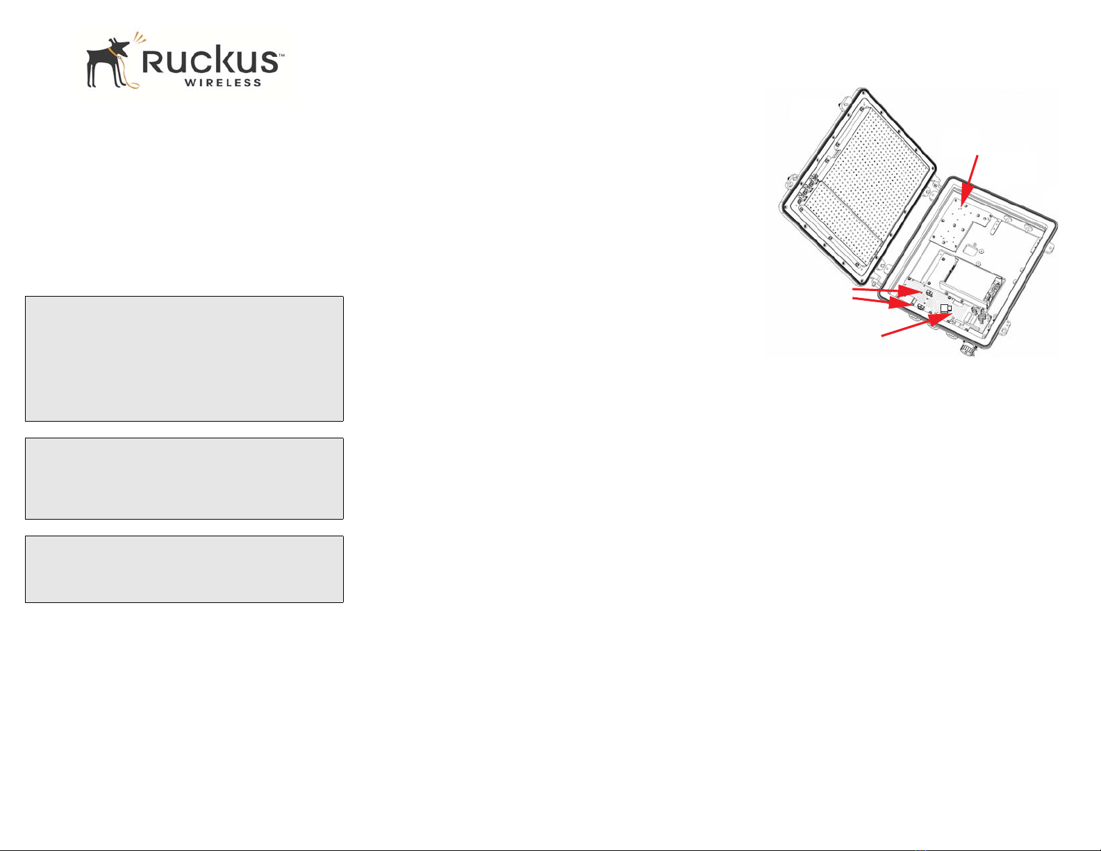
STEP 5: PLUGGING THE ETHERNET CABLE INTO
THE MEDIA CONVERTER
A. Take the Ethernet cable unplugged from the interface
circuit board in Step 4: Unplugging the Ethernet
Cable from the Interface Circuit Board, and plug it
into the media converter 10/100/1000 port.
B. Continue with Step 6A: Installing the
customer-supplied FOTC (fiber optic trunk cable) or
Step 6B: Installing the M25 Cable Gland, as required.
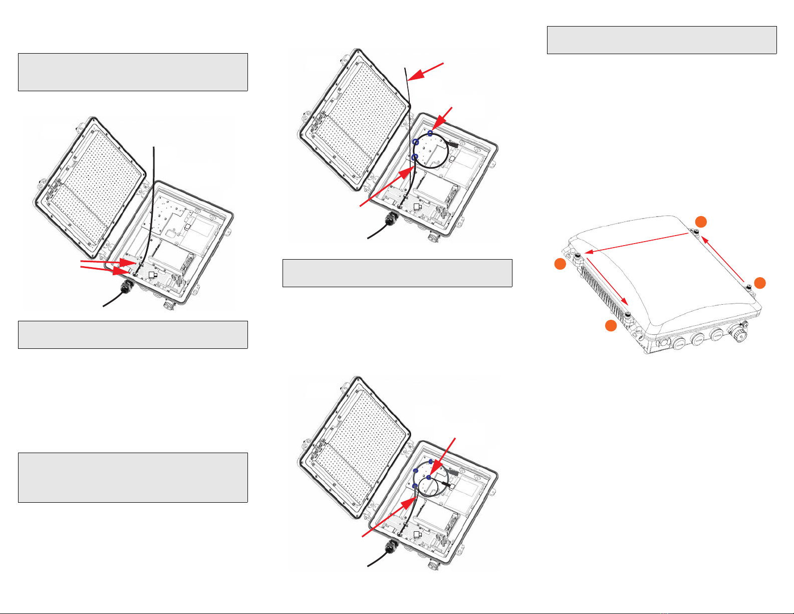
STEP 6A: INSTALLING THE CUSTOMER-SUPPLIED
FOTC (FIBER OPTIC TRUNK CABLE)
If you are not using a customer-supplied FOTC, then skip
this step and continue with Step 6B: Installing the M25
Cable Gland.
If you are using a customer-supplied FOTC:
A. Use a wide flat-blade screwdriver to remove the
FIBER blanking cap.
B. Assemble the M25-to-5/8" thread adapter with O-ring
and the strain relief cable connector. Make sure the
O-ring stays on the thread adapter.
C. Feed the connectorized fibers through the FIBER
opening. Do not force the fibers and do not tightly
bend the fibers.
D. Screw the thread adapter and strain relief cable
connector assembly into the cable gland opening.
E. Tighten the thread adapter and strain relief cable
connector assembly in the FIBER port until the O-ring
is compressed.
F. Continue with Step 7: Securing the Fiber-Optic Cable
Fibers Using the Locking Wire Saddles.
STEP 6B: INSTALLING THE M25 CABLE GLAND
If you are using a customer-supplied FOTC, then skip this
step and complete Step 6A: Installing the
customer-supplied FOTC (fiber optic trunk cable).
A. Use a wide flat-blade screwdriver to remove the
FIBER blanking cap, and replace with the cable gland.
B. Install the base of the cable gland in the FIBER port.
Use the 27mm hex socket to tighten the cable gland
base to 9.0 to 9.6 N.m (80-85 in-lbs).
C. Separate the cable gland locking ring and rubber
grommet from the cable gland base, and slip over the
end of the fiber-optic cable.
D. Gently feed the fiber-optic cable fibers through the
cable gland or the M25-to-5/8" thread adapter into
the SC8800-S chassis. Do not force the fibers and do
not tightly bend the fibers.
E. Hand-tighten the cable gland locking ring onto the
cable gland base until the rubber grommet is
compressed.
F. Continue with Step 7: Securing the Fiber-Optic Cable
Fibers Using the Locking Wire Saddles.
Plug in the Ethernet
cable here
CAUTION!
BE CAREFUL not to damage the FOTC fibers.
CAUTION!
BE CAREFUL not to damage the external antenna feed
cables.

Copyright © 2013 Ruckus Wireless, Inc. Page 4 of 4
Published November 2013, Part Number 800-70486-001 Rev A
STEP 7: SECURING THE FIBER-OPTIC CABLE
FIBERS USING THE LOCKING WIRE SADDLES
A. Secure the cable with the two locking wire saddles.
B. Continue with Step 8: Positioning the Cable Ties.
STEP 8: POSITIONING THE CABLE TIES
A. The Media Converter Kit includes four cable ties.
Depending on your cable type and planned fiber
routing, position the cable ties through any four of the
cable tie holders on the cable management plate.
Secure the cable ties in loops but leave them loose.
B. Continue with Step 9: Routing Out-of-Service Fibers.
STEP 9: ROUTING OUT-OF-SERVICE FIBERS
A. Gently route the in-service fiber to the side.
B. Route the out-of-service fibers through a few of the
loose cable ties.
C. Gently dress the cable ties. Do not overtighten and
crush the fibers.
D. Continue with Step 10: Routing In-Service Fiber.
STEP 10: ROUTING IN-SERVICE FIBER
A. Gently route the in-service fiber through one or more
of the loose cable ties.
B. Loosely dress the cable tie(s). Do not overtighten and
crush the in-service fiber.
C. Plug the terminated end into the SFP module.
D. Continue with Step 11: Fastening the SC8800-S Front
Cover.
STEP 11: FASTENING THE SC8800-S FRONT
COVER
A. Make sure that the gasket around the front cover is in
its channel.
B. Loosely close the front cover of the SC8800-S.
C. Tighten the four front-cover captive screws in the
order shown to 1.7 N.m (15 in-lbs).
D. Retighten the four front-cover captive screws in the
order shown to 2.3 N.m (20 in-lbs).
E. Retighten the four front-cover captive screws in the
order shown to 2.8 N.m (25 in-lbs).
You have completed the installation of the SC8800-S
outdoor access point media converter kit.
CAUTION!
BE CAREFUL not to damage the external antenna feed
cables.
NOTE:
The M25 Cable Gland is shown in this figure.
NOTE:
Refer to Step 9: Routing Out-of-Service Fibers and Step
10: Routing In-Service Fiber for possible cable tie
locations.
Secure cable
in locking
wire saddles
NOTE:
The M25 Cable Gland is shown in this figure.
Loose cable ties
(as required)
In-service fiber
Out-of-service
fibers
Loose cable tie(s)
(as required)
In-service fiber
NOTE:
The M25 Cable Gland is shown in this figure.
2
3
4
1
Other manuals for SC8800-S
2