Rugged Radios GMR5-M User manual

GMR5-M
P.N. GMR5-M

Thank you for purchasing a Rugged Radios 2-Way Radio. This radio was
pre-programmed and fully optimized before being shipped to you. Please
use caution before changing any settings on this radio. For questions,
please call the Rugged Radios Tech Department at 888-541-7223.
TYT Electronics
Co., Ltd.

USAGE TIPS ----------------------------------------------------------------------------- 2
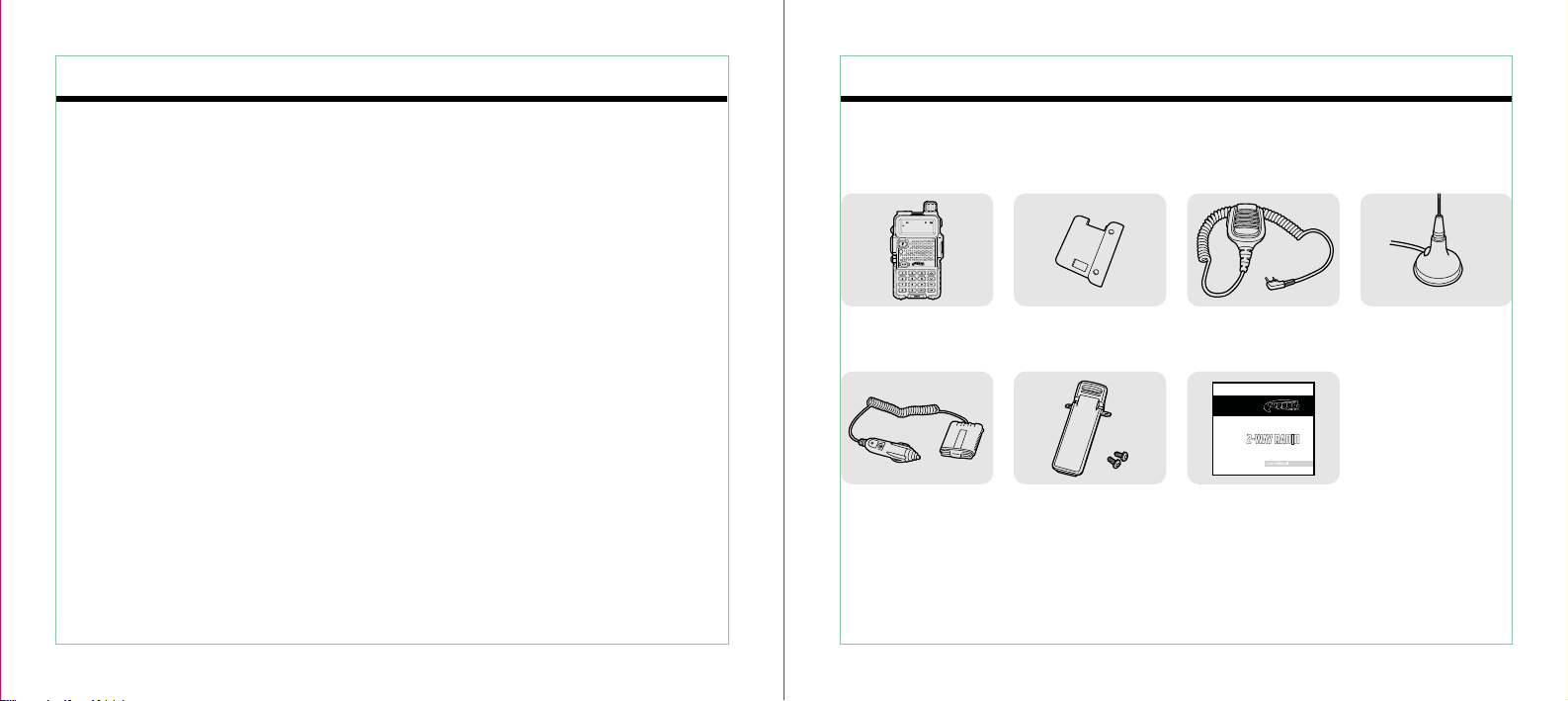
UNPACKING & CHECKING EQUIPMENT ------------------------------------------------- 3
CONFIGURATION ----------------------------------------------------------------------- 4
ACCESSORY INSTALLATION ----------------------------------------------------------- 7
GETTING FAMILIAR -------------------------------------------------------------------- 9
OPERATION MODES -------------------------------------------------------------------- 14
MENU ---------------------------------------------------------------------------------- 15
DETAILED FUNCTION DESCRIPTION --------------------------------------------------- 17
ADVANCED FUNCTIONS ---------------------------------------------------------------- 22
TECHNICAL PARAMETERS ------------------------------------------------------------- 25
WARRANTY REGISTRATION ------------------------------------------------------------ 27
FCC NOTICE
The GMR5-M Radio operates on GMRS (General Mobile Radio Service) frequencies which require a Federal
Communications Commission (FCC) license. You must be licensed prior to operating on channels 1-7,
15-22 or RP15-22, and RUGGED which comprise the GMRS channels of the GMR5-M. Serious penalties
may result from unlicensed use of GMRS channels in violation of FCC rules as stipulated in the
Communications Act Sections 501 and 502 (amended). You will be issued a call sign by the FCC that should
be used for station identification when operating your radio on GMRS channels. You should also cooperate
by engaging in permissible transmissions only, avoiding channel interference with other GMRS users, and
being prudent with the length of your transmission time.
To obtain a license or inquire about the license application, contact the FCC at 1-888-CALL-FCC or visit the
FCC website at http://www.fcc.gov and request form 605.
Contents
RF exposure waring:
This equiment complies with FCC radiation exposure limits set forth for an uncontrolled environment. This
equipment shall be installed and operated with minimum distance 44.8cm between the radiator & body.
For a transmitter that can only be operated with an FCC license,warnings concerning compliance with
applicable licensing requirements and information concerning license application procedures.

Usage Tips Unpacking & Checking Equipment
02 03
Please read the following instructions. Failure to comply with these instructions may be
dangerous or violate the law.
Check your package for the items listed below. If any items are missing or damaged during
shipment, contact your dealer.
GMR5-M Radio
Power Adapter Mounting Clip User Manual
Radio Mount Speaker Mic Magnetic Roof
Mount Antenna
• Obey local government regulations. Improper use may be punishable by law.
• Turn off the radio before entering flammable or explosive areas.
• Do not charge or change the battery in flammable or explosive areas.
• Turn off the radio before getting close to blasting zones or detonation areas.
• Do not use a radio with a damaged antenna. Touching a damaged antenna may cause heat
injury.
• Do not attempt to open the radio. Maintenance work should be done by technical experts only.
• To avoid trouble caused by electromagnetic interference or electromagnetic compatibility,
please turn off the radio in places with "Do Not Use Wireless Equipment" displayed, such as
hospitals or other healthcare facilities.
• In cars with airbags, do not keep the radio within the scope of airbag deployment.
• Do not store the radio under direct sunlight or in hot areas.
• When transmitting with the radio, always remain at least 35 inches from the antenna.
• If the radio appears or smells burnt or emits smoke, shut off power immediately and contact
your local dealer.
• Transmitting for an extended period of time may cause the radio to overheat and potentially
harm the user.
GMR5-M
P.N. GMR5-M
1-10
BFG RLY

04 05
Example of Radio Placement • Antenna should be mounted as high up on the vehicle as
possible, centered on the roof if possible.
• Carefully route the coax cable as to not have any pinches
or coils.
NOTE: Avoid interaction between the coax cable and power
cables.
Configuration Antenna Placement
MAGNETIC
ROOF MOUNT
ANTENNA
SPEAKER MICRADIO
POWER
ADAPTER

Power Adapter
06 07
1) Fit the supplied power adapter into the trough, then slide it toward the top of the radio to insert
it completely (in the direction the of arrowhead below)
2) Push the power adapter lock to release the power adapter and slide it toward the bottom of the
radio to remove it (in the direction the of arrowhead below)
Mounting Clip
1. Align the two holes of the mounting clip with the two holes of the radio and affix them with the
supplied M2.5x5 screws. Loosen the screws to remove the mounting clip.
2. Secure the GMR5-M to the radio mount as shown.

08 09
Speaker Mic Getting Familiar
With the radio turned off, open the cover of the microphone/speaker jack and insert the speaker
mic plug into the jack. Remote Antenna
Connector
Internal Speaker
Volume Dial
Keypad
Busy/TX
Internal Microphone
Indicator turns green
while receiving and red
during transmission or
emergency alarm.
Toggles tranceiver power
on/off and adjusts audio
levels.
BAT T EXIT
FM
1-10
BFG RLY
: Up & Down Arrow Keys
: Locks & Unlocks Radio
: Displays Battery Voltage
: Enter & Exit FM Mode
: Exit Key Functions & Menus

PTT
Mounting Clip
Microphone/Speaker Jack
Power Adapter
MONITOR
Press to transmit and release
to receive after your
transmission is completed.
The jack provides connection
points for microphone audio,
earphone audio, speaker
Pressing and holding this key
disables noise squelching
action, allowing you to hear
weak signals near the
background noise level.
10 11
LCD Display
Icons Description of Functions
Operating Band Signal & Power Meter
Low TX Power Active
Dual Watch/Standby Active
Repeater Shift Direction
Keypad Lock Active
Narrow Band Mode Active
The following table defines the icons that display on the radio LCD.

12 13
Icons Description of Functions
Squelch Active
Beep Tone Active
Battery Power Indicator
Set CTCSS Tone
Set DCS Tone
Operating A Band Indicator
Operating B Band Indicator
Frequency Mantissa Indicator
Channel Number/Menu Items Number Indicator
Busy Channel Indicator
Channel Scanned Available Under CH Mode
Keypad Functions
Press
key Enter Menu
mode/confirm
the setting
Upper menu
item, channel
or frequency
Lower menu
item, channel
or frequency
Switch
between VFL
Mode and
MR Mode/exit
the setting
Hold key
and turn on
radio
Channel delete
mode (will not
delete preset
channels)

14 15
Operation Modes Menu
1) Channel Mode (MR)
Use [ ] / [ ] keys to change or input frequencies by keypad directly and store channels.
2) Listen Only Frequency Mode (VFL)
In VFL mode, press [ ] to enter MR mode. The frequency will be indicated on the display and
the channel number will be indicated on the right side.
4) FM Radio Mode
GMR5-M provides 76.00-108.00MHz FM radio. In FM mode, you can choose the frequency you
need directly, scan frequency range, and store your favorite channels. Press [ ] to enter and
exit FM radio mode.
5) MENU Mode
Press [ ] key to enter MENU mode
No. LCD Display
01 SCAN Frequency/Channel Scan/
02 SQL SQL Level Setting0-9
03 DUALDSP Dual Wait/StandbyON/OFF
04 LED LED Display ModeON/AUTO/OFF
05 BACKLIT Background Light ColorCOLOR 1/COLOR 2/COLOR 3
06 BEEP Keypad Beeper SettingON/OFF
07 ROGER Receive End BeepON/OFF
08 BUSYLOK No Transmit Over CarrierON/OFF
09 VOICE Voice PromptON/OFF
10 ON MSG Power On DisplayOFF/VOLTS/MESSAGE
11 BATTERY Battery Power Voltage/
12 PON.MSG Power On Message-1A, @
13 TONE TX/RX Tone CoderOFF/67.0/D023N
14 RX-TONE RX Tone CoderOFF/67.0/D023N
15 TX-TONE TX Tone CoderOFF/67.0/D023N
Available Values Description of Function

16 17
Menu Operation Detailed Function Descriptions
1) In standby mode, press [ ] to enter menu setting. The LCD will display "MENU."
2) Press [ ] or [ ] to select the desired menu item. The LCD will display the current setting of
the selected item.
3) Press [ ] to enter, and then press [ ] or [ ] to select the desired setting.
4) Press [ ] to confirm.
5) Press [ ] twice to exit and return standby mode.
1) Scan & Scan Mode setting (SCAN)
Functions: Under VFL/MR mode, GMR5-M allows you to scan the entire current operating band
and memory channels.
2) Squelch Adjustment (SQL --- MENU 2)
Enter Menu 1st and press [ ] key to start scanning.
When you have started scanning, press [ ] / [ ] key to change direction. The radio will halt
on a signal it encounters. Press PTT key to stop scanning. Press MONI key to stop scanning
temporarily. Press [ ] key again to exit the scanning function.
Functions: The GMR5-M Squelch system allows you to mute background noise when no signal is
being received. The Squelch system significantly reduces battery consumption.
Enter Menu 2 to set SQL level. Default: 5
3) Dual Wait/Standby (DUALDSP --- MENU 6)
4) LED Display Mode (LED --- MENU 4)
Functions: Receive a sub band signal even while working on the operating band. Monitor signals
under both master and sub bands at the same time.
Functions: Select the LED/Keypad Lamp mode.
Enter Menu 4 to select LED display mode. Default: AUTO
Enter Menu 3 to set Dual Wait. Default: ON

18 19
ON: LED display lights all the time.
AUTO: Illuminates the LED when any key is pressed. Light turns off after 3 seconds.
OFF: Disable the LED lamp.
8) No Transmit Over (BUSYLOK --- MENU 8)
Functions: Prevent transmission over a present carrier.
Enter Menu 8 to set BUSYLOK. Default: OFF
9) Voice Prompt (VOICE --- MENU 9)
Functions: Enable/disable voice prompt.
Enter Menu 16th to set VOICE. Default: ON
10) Power-On Display Setting (ON MSG, BATTERY, PON. MSG. --- MENU 10, 11, 12)
11) Tone Coder (TONE, RX-TONE, TX-TONE --- MENU 13,14,15)
Many repeater systems require that a very-low-frequency audio tone be superimposed on your
FM carrier in order to activate the repeater. This helps prevent false activation of the repeater by
radar or spurious signals from other transmitters.
Many repeater systems require that a very-low-frequency audio tone be superimposed on your
FM carrier in order to activate the repeater. This helps prevent false activation of the repeater by
radar or spurious signals from other transmitters.
• Press [ ] key to select CTCSS/ DCS/ OFF. After you choose CTCSS/DCS, press [ ] / [ ]
keys to choose the right group you need.
• Press [ ] key to select DCS direction.
The GMR5-M has 50 CTCSS groups and 104 normal/inverted DCS groups.
Functions: Choose power-on display mode and edit power-on message.
Function 1: CTCSS/DCS Operation
Enter Menu 10 to set ON MSG. Default: OFF
Enter Menu 11 to check battery voltage.
Enter Menu 13, 14, 15 to set TX & RX Tone coder, RX Tone coder, TX Tone coder.
Enter Menu 12 to edit power-on message, also you can edit it directly with program software.
5) Background Light Color (BACKLIT)
Functions: Choose LED background light color.
COLOR1: Purple
COLOR2: Blue
COLOR3: Orange
OFF: Displays model version
VOLTS: Battery power voltage
MESSAGE: Power-on message
Using [ ] / [ ] to select character;
Enter Menu 5 to select background light color. Default: COLOR1
6) Keypad Beeper Setting (BEEP)
Functions: Enable/disable the keypad beeper.
Enter Menu 6 to set keypad beeper. Default: ON
7) Receive End Beep (ROGER --- MENU 7)
Functions: Beeps to inform that receiving is over.
Enter Menu 7 to set ROGER. Default: OFF

20 21
Note: Also known as PL/CT/CTCSS Tones. Privacy codes can be programmed for use on any
channel.
Privacy Tones Frequency Chart (Hz)
67.0
71.9
74.4
77.0
79.7
82.5
85.4
88.5
91.5
94.8
97.4
100.0
103.5
107.2
110.9
114.8
118.8
123.0
127.3
131.8
136.5
141.3
146.2
151.4
156.7
162.2
167.9
173.8
179.9
186.2
192.8
203.5
210.7
023
025
026
031
032
036
043
047
050
051
053
054
065
071
072
073
074
114
115
116
122
125
131
132
134
143
145
152
155
156
162
165
172
174
205
212
223
225
226
243
244
245
246
251
252
255
261
263
265
266
271
274
306
311
315
325
331
332
343
346
351
356
364
365
371
411
412
413
423
431
432
445
446
452
454
455
462
464
465
466
503
506
516
523
526
532
546
565
606
612
624
627
631
632
645
654
662
664
703
712
723
731
732
734
743
754
218.1
225.7
233.6
241.8
250.3
CTCSS
DCS Codes

22 23
Advanced Functions
In standby mode, press [ ] for 2 seconds to lock or unlock the keypad. [ ] will be displayed at
the top of the LCD when keypad is locked.
1) Keypad Lock Settings
3) FM Radio Function
On/Off Radio Receiver
In standby mode, press [ ] to open FM radio function. LCD will display "76.00."
Pressing [ ] again will exit FM radio mode.
Mode Selection
In FM radio mode, press [ ] to switch between FM memory mode and FM frequency mode.
Note: This function is unavailable when there are no FM memory channels.
Frequency Selecting
In FM frequency or memory mode, input digits directly by keypad or press [ ] or [ ] to
choose the desired frequency or stored FM channel.
FM Radio Search
In FM radio mode, press [ ] + [ ], then press [ ] again to enter FM
radio scanning. On the "RADIO" screen, press [ ] or [ ] to change scanning
direction. The radio will stop scanning when a frequency is available and then exits.
FM Radio Storage
In FM frequency mode, press [ ] and then press[ ]. The channel number for storage
will blink at the right of the screen. Press [ ] or [ ] or use number key to select the desired
channel number and press [ ] to confirm.
FM Radio Channel Delete
In FM memory mode, turn off the radio. Press [ ] to turn on the radio. "DEL ?"
will appear on the screen and the channel number will blink. Press [ ] or [ ]
to choose the channel number you wish to delete, then press [ ] to confirm.
Note: In FM radio mode, if a signal is received, the radio will exit FM mode. The radio will return
to FM mode 5 seconds after signal ends.
To access a repeater, press and hold the [ ] key for the amount of time specified by the
repeater. The transmitter will automatically be activated, and a 1750Hz audio tone will be
superimposed on the carrier. Once access to the repeater has been gained, you may release the
[ ] key and use PTT for activating transmission.
2) Tone Calling (1750Hz Tone)

24 25
Technical Parameters
Listen Only Frequency Range
Channel No.
Frequency Stability
Antenna
Antenna Impedance
Operating Voltage
Mode of Operation
Dimensions (WxHxD)
462.550-462.7250MHz,462.5625-462.7125MHz,
2x128
±2.5PPm
High Gain Antenna
50Ω
12 Volts (With Power Adapter)
Simple or Semi-Duplex
110x58x32mm (Not Including Antenna)
General
Note: Specifications may be revised without notice due to technical improvement.
Transmitter
Modulation Mode
Maximum Deviation
Spurious Radiation
Adjacent Ch. Power
Pre-emphasis Characteristics
Current
CTCSS/DCS
Intermediation Sensitivity
Intermediation Distortion
< 5kHz / < 2.5KHz
< 7.5μW
< -65dB / < 60dB
6db
< 1.6A(5W)
0.5kHz±0.1kHz / 0.4kHz±0.1kHz
8-12mv
< 5%
Receiver
RF Sensitivity
Audio Power
Audio Distortion
Intermediation
Selectivity
Spurious Rejection
Blocking
-122dBm(12dB SINAD)
1W
< 10%
> 60dB > 55dB
> 65dB > 60dB
> 65dB
> 85dB
467.550-467.7250MHz
11K0F3E

26 27
Rugged Radios Intercoms, Radios, and Headsets are backed by a 3-year warranty. For more
information, or to register your product, please visit our website.
Product Registration: www.ruggedradios.com/warranty
Questions: 888.541.7223
Model Number:
Serial Number:
Purchase Date:
Purchase Location:
Name:
Phone:
Email:
Warranty Registration
Notes
Table of contents
Other Rugged Radios Two-way Radio manuals