Ruihua PS1002 User manual

Ningbo Ruihua Electronic Plastic Co., Ltd.
Product specification
Product Name: Power Station
Product model: PS1002
Special description:
Confirm the signature
Production business engineering
Address: Website No. 49, Zhennan Road, Ditang Street, Yuyao City, Zhejiang Province, China
http://www.nbruihua.com

1.Overview
Products are designed for mobile office,
long distance transmission,
Smart device power supply,
Safe and reliable, excellent electrical conductivity;
Recoverable overload protection device can effectively protect the use of electrical appliances.The built-in reactive
power compensation circuit is used to increase the power factor, adjust the grid voltage, reduce the line loss, improve the
power quality, and thus save 10%~30% of the power.It is especially effective for power consumption when starting a
motor type such as a refrigerator or a washing machine.
No solder joints, high-quality copper sheets are resistant to plugging and insertion, and the meshing technology is
elastic. The large pitch holes are convenient for plugging and unplugging the jacks and no longer interfere with each other.
four usb jack outputs match more smart devices.
The main functions are as follows:
9-way ac output
4 usb sockets
Wireless Router
Surge protection
FCC STATEMENT
1. This device complies with Part 15 of the FCC Rules. Operation is subject to the following two
conditions:
(1) This device may not cause harmful interference.
(2) This device must accept any interference received, including interference that may cause
undesired operation.
NOTE: This equipment has been tested and found to comply with the limits for a Class B digital
device, pursuant to Part 15 of the FCC Rules. These limits are designed to provide reasonable
protection against harmful interference in a residential installation.
This equipment generates uses and can radiate radio frequency energy and, if not installed and
used in accordance with the instructions, may cause harmful interference to radio communications.
However, there is no guarantee that interference will not occur in a particular installation. If this
equipment does cause harmful interference to radio or television reception, which can be
determined by turning the equipment off and on, the user is encouraged to try to correct the
interference by one or more of the following measures:
Reorient or relocate the receiving antenna.

Increase the separation between the equipment and receiver.
Connect the equipment into an outlet on a circuit different from that to which the receiver is
connected.
Consult the dealer or an experienced radio/TV technician for help.
Warning: Changes or modifications to this unit not expressly approved by the part responsible for compliance could void the
user's authority to operate the equipment.
FCC Radiation Exposure Statement
The device has been evaluated to meet general RF exposure requirement. The device can be used in fixed/mobile
(min20cm)exposure condition without restriction.
2.Product parameters
Product number PS1002
Electrical parameters
Rated voltage 120V~
Maximum current 12A
Maximum power 1440W
Usb output 5V-2.4Amax
WiFi routing parameters
Lan port (device connection port) 100M network port
Wan mouth (network cable access
port) 100M network port
Transmission standard IEEE 802.11n;IEEE 802.11g;IEEE 802.11b;IEEE 802.3;IEEE
802.3u
Transmission band 2.4GHz frequency band
Network protocol Tcp/ip protocol
Wireless protocol 802.11n
Wireless rate 300Mbps
safety standard WPA-PSK/WPA2-PSK
Transmission distance Recommended about 110 square meters
Product Size 345.5*180*59.5mm
product weight ≤1Kg (net weight)
3.Environmental conditions
Serial number project Technical indicators unit Remarks
1 Operating temperature -30 -- +50 ℃
2 Storage temperature -40 -- +70 ℃
3 Relative humidity 5 -- 95 %

4
Altitude
≤2000
M
5
cooling method
Natural cooling
Stay away from hot areas
4.Panel introduction
1. Switch panel:
○
1 Surge indicator ○
2 Left socket switch ○
3 Usb switch
○
4 Right socket switch ○
5 Power Indicator
2. USB socket and WiFi panel
○
1 USB socket ○
2 WiFi routing switch ○
3 Wired network input

○
4 Wired network output ○
5 WiFi routing switch to restore factory button
3. Socket panel:
○
1 Ac input socket ○
2 Ac output socket ○
3 Ac output socket ○
4 Overload protector
4.Introduction to WiFi routing settings
Product default routing mode, open the WiFi power switch Connect the network
cable and set it up, and the WiFi route will send a “B-LINK-XXXXXX”wireless network
name, the initial state is no password open.Commonly used settings are wireless relay mode
and routing mode, which can be operated on the phone or computer:
5.Wireless relay mode setting:
①Open the phone wlan list,
②Open your phone web browser,
Connect to the wireless network address bar of b-link-xxxx and enter 192.168.16.1 click to access
Enter the username and password (default is admin) to log in to the router.
Phone operation steps

③Click on the routing settings,
④Select the wireless network to relay,
Swipe to find mode switch Click to enter the input selection network password click save to take effect
Select universal relay mode (wisp)
⑤Choose the way to access the Internet, ⑥Set the router to restart automatically.
Select Dynamic Acquisition Click Next to return to the phone Wlan list, connect to the settings after the
wireless network Set the WiFi name and password and click Save to take effect. Note: The system restart
time is about 30S.After rebooting, you can log in again to view
Router Routing Mode Internet
Up going Rate:0B/s
Downlink
Rate:OB/s
Routing Status
Routing Settings
Welcome to use Router
00000
onLogon
00LLo
gon
ogon
000
…
Logon
channel Wi-Fi Name Strength
1 1111111111
1 360 free WiFi-54
1 110110
2 ChinaNet-3sti
3 Xiaomi-8E64
6 TP-Link-086E
Relay Mode
Client Mode
AP(Access Point)Mode
Universal Relay Mode(WISP)
Routing Mode
AP(Access Point)Mode
Relay Mode
Client Mode
Universal Relay Mode(WISP)
Routing Mode
←Mode Switch
step up
re-scan
←Mode Switch
channel Wi-Fi Name Strength
1 1111111111
1 360 free WiFi-54
1 110110
2 ChinaNet-3sti
3 Xiaomi-8E64
6 TP-Link-086E
2.4GChannel Setup
2.4G Signal Strength
Wi-Fi Closing Time
Network Speed
Measurement
Mode Switch
Panel Lighting Switch
Blacklist
WLAN
Available WLAN List
B-LINKAD7134
Connected(No Internet access)
Xiaomi8E64
Saved,Encryption(
good network quality
)
TPLINK_2E2A
Saved,Encryption(Internet access)
11011
Encryption
111111
Encryption
192.168.16.1 Visit
←WLAN …
⁞⁞⁞
Routing Status
Routing Settings
CPU Terminal On-line Time
8% 1 0:0:28:44
Wi-FiName
Password
xiaomi_8E64
←Mode Switch
12345678
Save Effective
Cancel
2
1

.
1. Routing mode settings:
step up
next step
←Mode Switch
Broadband Dynamic Static
Number Acquisition Settings
Equipment Connection
Available WLAN List
B-LINKAD7134
Connected
(
good network quality
)
Xiaomi8E64
Saved,Encryption
(
good network
quality
)
TPLINK_2E2A
Saved,Encryption(Internet
access)
If using ADSL Internet broadband Internet access, please follow the following figure 1, 2, 3, 4, 5 order connection;If you use the broadband network in the community,
please connect in the sequence of 3, 4 and 5 as shown in the figure below, and connect the WAN of the router directly to the broadband network in the community.
ON/OFF
Wi-Fi Name
Wi-Fi Password
Telephone
Telephone line
ADSL MODEM
Speech separator
B-LINK-AD7
134
12345678
Save Effective
step up
2.4G Wi-Fi
←Mode Switch
←WLAN
…
⁞⁞⁞
B-LINK-AD7
134
12345678
Save Effective
step up
2.4G Wi-Fi
←Mode Switch
Wi-Fi Name
Wi-Fi Password
The router is
rebooting,Expectation
67s
USB X4
Computer operation steps
ADSL Broad band
access
LIN IN
LIN OUT
Reset
Telephone line
Telephone line
Ethernet cable
Community broadband access
Ethernet cable
Ethernet cable
Wireless connection
warning
1. In thunderstorm weather, please remove the
power supply and all connections of the
equipment to avoid lightning strike;
2.Keep away from heat and maintain ventilation;
3. In the storage, transportation and operation
environment, please pay attention to
waterproofing;
4. Use rated power adapter;
5. Place equipment on a level, flat surface.
After connecting, please check whether the indicator light is normal
Indicator
light
Name
normal state
(WPS)wireless
encryption
indicator light
Trigger WPS connection, blink;
Connection successful, stop
flashing;
Wireless status
indicator
Always bright or flashing
(WAN) WAN
Status
indicator
Port connected, indicator light
On:
There is data transmission,
indicator light flashing
(LAN) LAN
Status
indicator light
Port connected, indicator light
On:
There is data transmission,
indicator light flashing
Power
indicator
Normally on
use ADSL Broadband Internet Access,Please click 1, 2, 4 and 5 to connect in sequence in the picture below;If you use
cell broadband,Please click 3, 4 and 5 below to connect in sequence,To put the WAN Direct access to cell broadband.

Automatic Access IP Address(D)
Automatic Access DNS Server Address(B)
Use the following DNC server address (S)
Conventional Standby configuration
Automatic Access DNS Server Address(B)
Use the following DNC server address (S)
Automatic Access DNS Server Address(B)
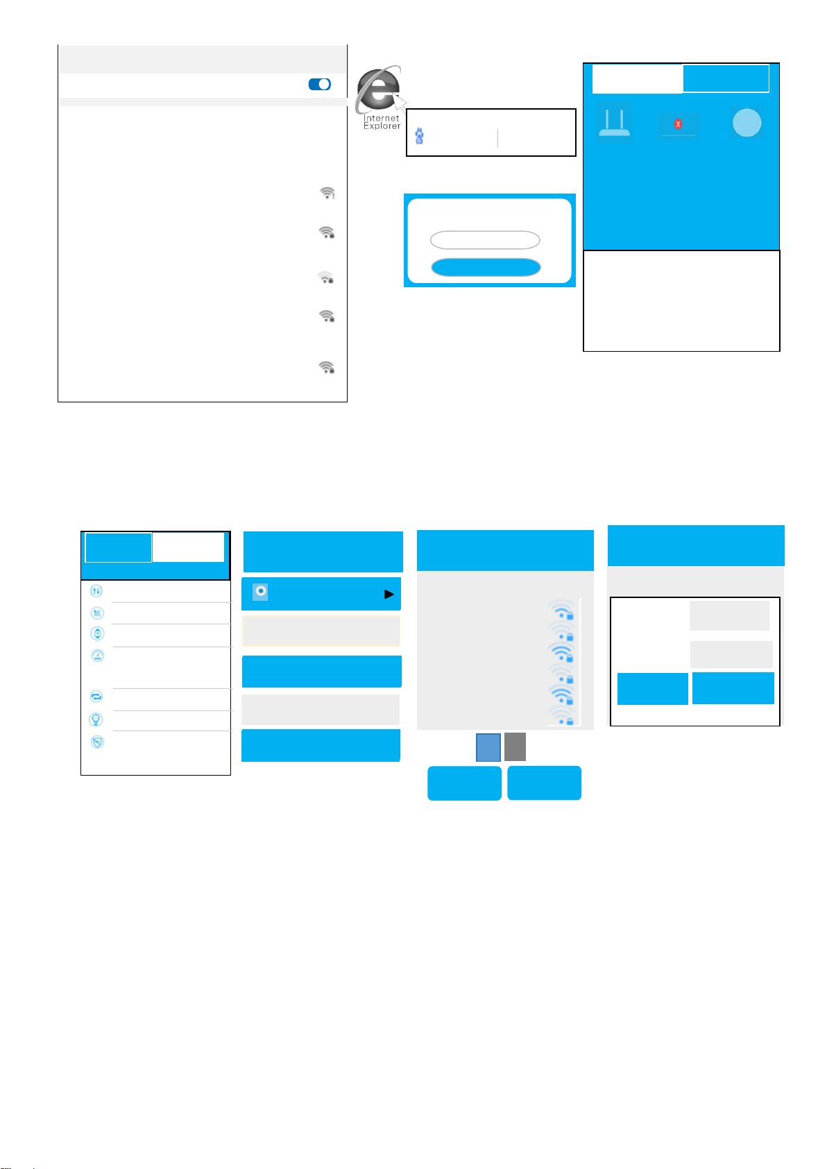
2. Computer ip address setting
0
Windows 2000 or Windows XPP lease click the following steps to set up.
Right-click on the
desktop"Online
Neighbor"Select"Property"The
n right-click on"Local
Connections",Select"Property"
Select"Automatic Access IP
Address"and"Automatic Access
DNS Server Address",Click"Make
sure"Back to the last
interface,Click on"Make sure"
Local connection
Have even on
Disable (B)
State (U)
Repair (P)
The bridge (G)
Create shortcuts
(S)
Delete (D)
Rename (M)
Double click"Internet
Agreement(TCP/IP)"
Conventio
n
al
senior
AEGIS Protocol (IEEE 802.1X) V3.7.5.0
instructions
TCP/IP is the default wan protocol that provides
communication across multiple internetworks.
Automatic Access DNS Server Address(B)
Advan
ced
(V)
Display icon in notification area after connection (W)
Notify me when this connection is restricted or
disconnected (M)
Disable (B)
Connect/disconnect (O)
State (U)
Diagnosis of (I)
Bridge (G)
Create shortcuts (S)
Delete (D)
Rename (M)
local connections
Click “start →control panel →network
and Internet→network and share
center”→manage network
connections (change adapter Settings)
→local connections”, right-click “local
connections”, and “select properties”.
Use when connecting
Internet Agreement(TCP/IP)
Network Monitor Driver
determin
e
Local connection attribute
Automatic Access IP Address(D)
Realtek Pcle GBE Family Contr
Use the following DNC server address (S)
cancel
network
Local connection attribute
Set up(c)
Intel
®pro/1000 MT Network Connection
PreferrAed DNS server (P)
Standby DNS server (A)
Microsoft web client
QoS packet planner
Microsoft network file and printer sharing
Internet Agreement versions 6 (TCP/IP v6)
Link-layer topology discovery mapper I/O driver
Link-layer topology discovery responder
describe
TCP/IP. This protocol is the default wide-area
network protocol, which provides communication
on different interconnected networks.
Preferred DNS server (I)
Standby DNS server (U)
Use the following IP address (S)
If the network supports this feature, you can get automatic
assignment IP Settings.Otherwise, you need to buy the
appropriate IP Settings from the network system administrator.
Conventional Standby configuration
Installation(N)
Uninstall(U)
Propert(R)
determin
e
cancel
WindowsVista or Windows7 lease click the following steps to set up.
Select"Automatic Access IP
Address"and"Automatic Access
DNS Server Address",Click"Make
sure"
Back to the last interface,Click
on"Make sure"
Double click"Internet Agreement
versions 4(TCP/IPV4)"
Property(R)
Property(R)
Use when connecting
Set up(c)
Use the following items when connecting :(O)
Internet Agreement versions 4(TCP/IP v4)
Installation(N)
Uninstall(U)
Propert(R)
Internet Agreement(TCP/IP)
Use the following DNC server address (S)
Automatic Access DNS Server Address(B)
Use the following IP address (S)
Preferred DNS server (I)
Standby DNS server (U)
Advan
ced
(V)
Verify the Settings when exiting
PreferrAed DNS server (P)
Standby DNS server (A)
If the network supports this feature, you can get automatic
assignment IP Settings.Otherwise, you need to buy the
appropriate IP Settings from the network system administrator.
Internet Agreement versious4(TCP/IPv4)Property
Conventional Standby configuration
Automatic Access IP Address(D)
determin
e
cancel
determin
e
cancel

Terminal Number
Terminal
List
Firmware version number:1.0.1
Upload Total Memory Time
488B/S 57.10MB 03:18:20
Download Remaining Memory CPU Occupancy rate
568B/S 30.70MB 0%
3. Router settings
TWO
Mode
Switch
Terminal Number
Enter 192.168.16.1 in the address bar and click
to enter the login password (default is admin)
to log in to the router.
Go to the router management page
The management page can view the router status. Select mode switch to set the router
working mode. The operation method is the same as the previous relay mode.
Estimated
upgrade
Current routing status connection type
Connected Dynamic access
Terminal
List
Local IP address
192.168.16.1
Outer network IP address
192.168.1.203
MAC address
14:68:9C:RD:71:34
My Route
Expended
function
Expended
function
Cable equipment ONE 2.4G equipment TWO
Logon password
Welcome to use Router
Login
Mode
Switch
Terminal
List
Upload Total Memory Time
488B/s 57.10MB 0:3:18:20
Download Remaining Memory CPU Occupancy Rate
568B/s 30.70MB 0%
......
Double-click on the following icon
to open a web browser.
My Route
Estimated
upgrade
Internet
Explorer
Table of contents
Popular Portable Generator manuals by other brands

Mase Generators
Mase Generators VOYAGER Use and maintenance manual

Winco
Winco PSS20B2W/D Installation and operator's manual

Analog way
Analog way SPU001 quick start guide

DAYLIFF
DAYLIFF DG3600D Installation & operating manual

Mase Generators
Mase Generators IS 6.1 Use, maintenance and installation manual

Daewoo
Daewoo DDAE8000SE user manual