-10-
12-94
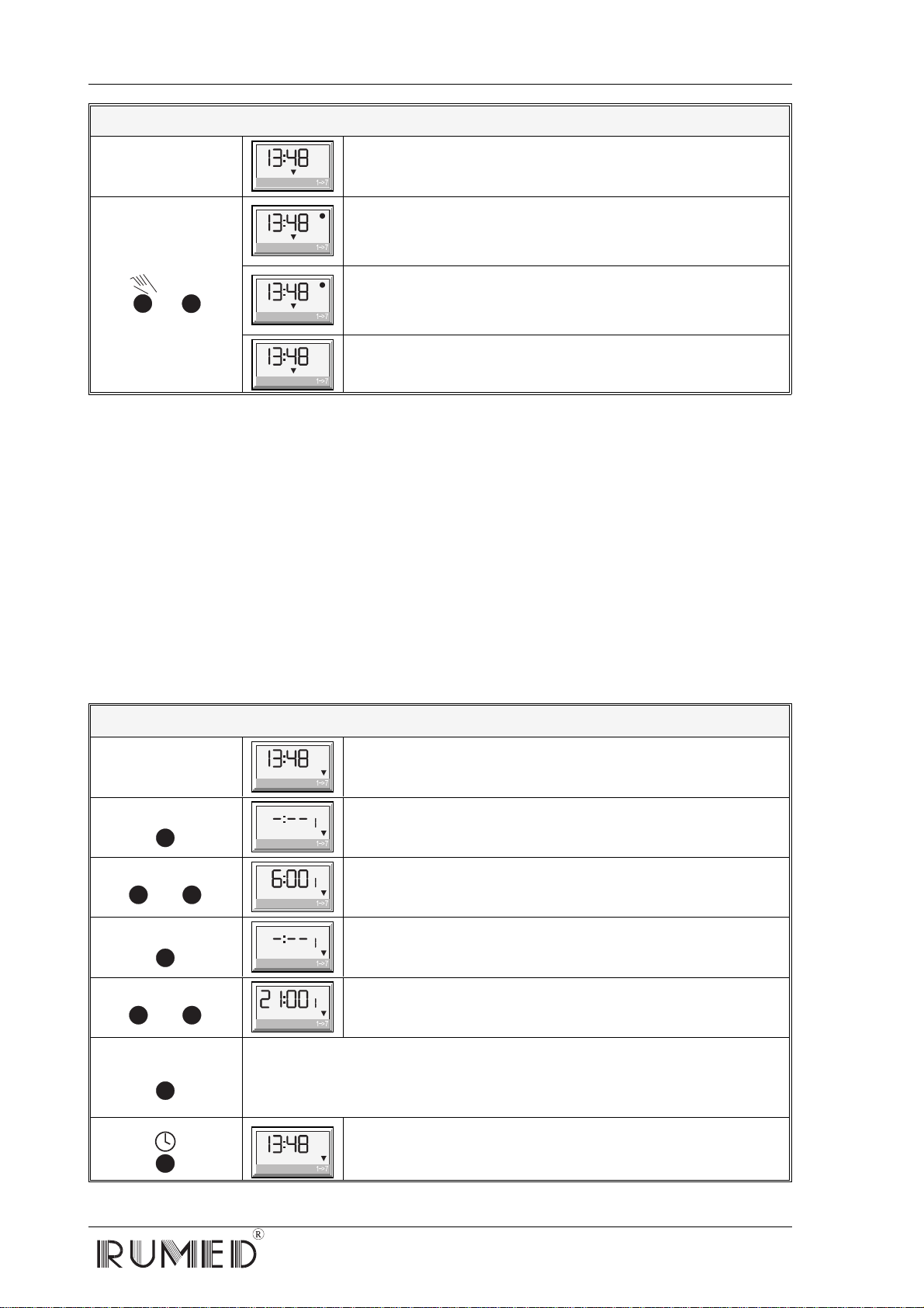
Change of the Switching Status
OFFOF
1234567
Clock indicates the actual time
(f. ex. 13.48 h) Switching status is "Automatic OFF"
+
m
ON
1234567
Press and hold key m and press key Hand once. The switching
status will change-over to "PERMANENT ON"
(display indicates a point above ON)
OFFOF
1234567
Press and hold key m and press key Hand once. The switching
status will change-over to "PERMANENT OFF"
(display indicates a point above OFF)
OFFOF
1234567
Press and hold key m and press key Hand once. The switching
status will again change-over to "AUTOMATIC" (point disappears)
Daily Programme
When the mode "daily programme" is activated, maximum 6 ON- and 6 OFF-commands can be
programmed. However, for one programme cycle only 1 ON- and 1 OFF-command is required. The
command ON starts the programme, the command OFF terminates the programme. At the same time,
a programme reset is effected in the temperature controller, which is the only possibility for a further
programme start.
Correspondingly, the time delay between an OFF-command and the next ON-command must be at
least 1 minute, otherwise the programme reset cannot be effected and the programme controller will
not change to the next programme cycle (i. e. in the operating mode "daily programme" it is possible to
run a four-hour programme cycle six times per day maximum).
The following table shows the programming of the response times for our dual setpoint programme
example.
Programming On- and Off-Commands (Operating Mode "Daily Programme")
OFFOF
1234567
Clock indicates the actual time
(f. ex. 13.48 h)
Prog.
ON
1234567
Press once, to call the programming mode
(Here: f. ex. not yet programmed)
or
h
m
ON
1234567
Enter time for the command 1 ON by means of the keys h
and m(Here: f. ex. 6.00 h)
Prog.
OFFOF
1234567
Press once, to call the command 1-OFF
(Here: f. ex. not yet programmed)
or
h
m
OFFOF
1234567
Enter time for the command 1 OFF by means of the keys h
and m(Here: f. ex. 21.00 h)
Prog.
There are no further switching commands required for our example
programme! If requested, all other switching commands can be called
successively on pressing the key Prog.
(2 OFF, 3 ON, 3 OFF, 4 ON, 4 OFF, 5 ON, 5 OFF, 6 ON, 6 OFF ☛after 6 OFF, 1 ON 1 OFF etc. will be repeated)
OFFOF
1234567
Press once, to terminate the programming mode and to
return to the normal display (If there will be no entry within 30 sec., the
display will automatically return to actual time).