www.victorruoshui.co.kr
이자료는 저작권법에 따라 보호받는 저작물이므로 무단배포 및무단복제를 금하며, 내용의 전부 또는 일부를 이용하려면, 반드시 한국 VictorRuoshui 社의서면동의를 받아야 합니다.
(3) Connect the alligator clips to the inductor leads.
(4) Read the display. The value is direct reading in the electrical
units (uH, H) indicated at the selected switch. If DISPLAY
show “1”. It indicates on Out-of-Range measurement. If the
display indicates one of more reading zeros, shift to the next
lower range scale to improve the resolution of the
measurement.
NOTE:
(a) If the inductance value is unmarked, start from the 2mH
range and keep increasing until the over range indication goes
off and a reading is obtained.
(b) Very low inductance measurement should be performed by
using extremely short leads in order to avoid introducing any
stray inductance.
(c) This instrument is not intended for determining the “Q”
factor for the inductor. Misleading readings may be obtained
if the measurement of the inductance of a resistor is
attempted.
(d) At range 2Mh,short –circuit the test leads,to measure the
inductance value ,then substracts it from the real
measurement .
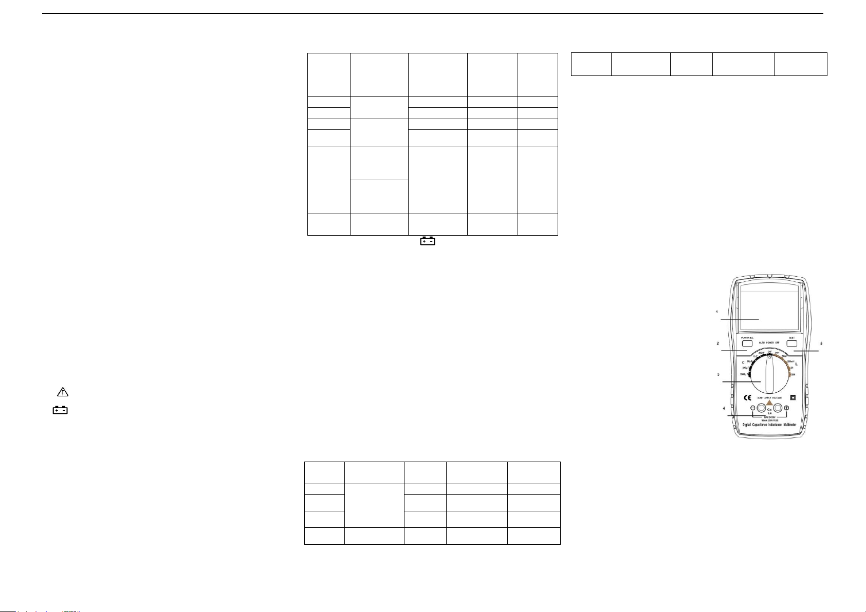
4-4.CAPACITANCE(C) MEASURING PROCEDURE
(1) Set POWER switch to “ON” position.
(2) Select the range switch for the maximum expected
capacitance.
(3) Fully discharge any capacitors.
(4) Connect the alligator clips to the capacitor leads.
(5) Read the display. The value is direct reading in the electrical
unit (nF, uF) indicated at the selected range switch. If
DISPLAY show “1”, It indicate on Out-of-Range
measurement. If the display indicates one or more leading
zeros, shift to the next lower range scale to improve the
resolution of the measurement.
NOTE:
(a) If the capacitance value is unmarked, start from the 2nF
range and keep increasing until the over-range indication
goes off and a reading is obtained.
(b) A shorted capacitor will read over-range on all ranges. A
capacitance with low voltage leakage will read over range,
or a much higher value than normal.
An open capacitor will read zero on all ranges (possible a few
pF on 2nF range, due to stray capacitance of the instrument).
(c) Very low capacitance measurement should be performed by
using extremely short leads in order to avoid introducing any
stray inductance.
(d) When using the optioned test leads, remember that the leads
introduce a measurable capacitance to the measurement. As
a first approximation, the test capacitance did measured by
opening the leads at the trips, recording the open circuit
value and subtracting the value.
(e) Capacitors, especially electrolytic, often have notoriously
wide tolerances. Do not be surprised if the measured value is
greater than the value marked on the capacitor, unless it is a
close tolerance type. However, value is seldom drastically
below the rated value.
5. MAINTENANCE
DO NOT try to verify the circuit for it’s a precision meter.
1.Beware of waterproof, dustproof and shockproof.
2.Do not operate and store the meter in the circumstance of high
temperature, high humidity, and flammability, explosive and
strong magnetic field.
3.Use the damp cloth and soft solvent to clean the meter, do not
use abrasive and alcohol.
4. If do not operate it for a long time, should take out the battery.
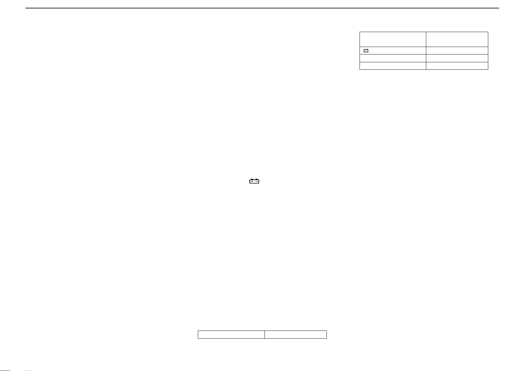
5.When LCD displays “”symbol, should replace the
battery as below:
(a). Ensure the instrument is not connected to any external circuit.
Set the selector switch to OFF position and remove the test
leads from terminals.
(b). Remove the screw on the bottom case and lift the bottom
case.
(c). Remove the spent battery and replace it with a battery of the
same type.
FUSE REPLACEMENT
Use the same type fuse as specified.
1. Remove the screw on the back of the case.
2. Replace the fuse with a new one .
3. Reinstall the screw in the case bottom.
6. TROUBLE SHOOTING
If the meter does not work properly, check the meter as
following:
●Power is off
●Replace battery
●The specifications are subject to change without
notice.
●The content of this manual is regarded as correct,
error or omits Pls. contact with factory.
●We hereby will not be responsible for the accident and
damage caused by improper operation.
●The function stated for this User Manual cannot be
the reason of special usage.
601E-6243-001A