General Information 3
General Information
Safety Informations
Only authorized profes-
sional electricians are
allowed to work on the
230 V power supply!
Potential risk of death
due to electric shock!
Disconnect the power supply
before performing any instal-
lation tasks!
Follow the currently valid stand-
ards and directives in order to fulfill
the general safety regulations for
telecommunications equipment
and to prevent interference. In
combined systems, make sure
there is shock protection for the
high voltage section. According to
DIN VDE 0620, protection against
shock must also be guaranteed
after you have remove the shared
cover (this is not always the case
in older systems).
When setting up combined
systems, make sure to maintain
the minimum distance of 10 mm
between data and telecommu-
nication lines and high-voltage
power cables.
Working on existing data networks
may require the consent of the
corresponding network/data
protection officer, and it may also
be necessary to create a data
backup prior to the work.
Please note the permissible oper-
ating temperature as well. Never
place the AC WLAN directly next
to devices that generate a lot of
heat (e. g. dimmers).
Proper Use
This device has three operat-
ing modes. It can be used as an
access point for devices commu-
nicating wirelessly or as a repeater
to extend the range of the WLAN
network. Furthermore, it can be
connected to devices that do not
have their own WLAN adapter.
Do not use the device for any
other purpose. Only operate the
device indoors.
General Information
The AC WLAN offers an excel-
lent alternative for fulfilling the
requirements of modern network
infrastructures according to DIN
18015-2 and RAL-RG 678 without
having to go without the flexible
use of modern, mobile tech-
nologies such as tablet PC‘s or
laptops, for example, or having to
restrict the wireless data rate.
In addition, the AC WLAN oper-
ates like a normal wall outlet box
with an RJ45 outlet for a conven-
tional data end device (data rate
100 Mbit/s). Power is supplied via
the 230 V connection on the back
of the device. The AC WLAN is
connected to the internal data net-
work using a classic copper data
cable, but also using a polymer
optical fiber (POF) cable.
The WLAN range can be adapted
to the conditions of the room and
can be restricted to the room.
This creates powerful room wire-
less cells that ensure the maxi-
mum bandwidth is available in the
room while simultaneously ensur-
ing low power consumption and
low emissions.
Due to its low power requirement
and resulting low emissions,
separation problems between
individual access points, overlap-
ping between WLAN areas, and
lowered data rates are avoided for
the most part. The AC WLAN can
be controlled directly via UDP.
It is the first WLAN access point in
the world to fit in a commercially
available installation box, and it
also fits in with all of the designs
offered by renowned switch
manufacturers.
System Requirements
· Connection to a LAN via a
copper network cable or, as an
alternative, a POF cable
· Internet browser
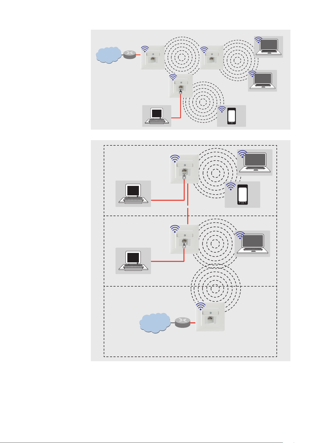
Access Point
Connection of the end devices
in the building to the Internet via
WLAN and RJ45 outlet
· Hard-wired network connection
via a POF or Cu connection
· Interface to the LAN/Internet
· Mode: Access Point
Access Point
Connection of the end devices to
the Internet via WLAN using the
existing installation with a patch
cable
· Mode: Access Point
Function Types
The AC WLAN operates as an
interface for wireless communica-
tion devices in the network. All
devices in the network can com-
municate with each other.
If the AC WLAN is connected to
a network router without a WLAN
interface, then WLAN devices can
also obtain access to the network
router through the AC WLAN.
When using more than one AC
WLAN, the base station and the
client must have the same SSID,
the IP address must be in the
same range (e.g. 192.168.0.xxx),
and they must use the same
encryption method.
The MAC address of the base sta-
tion must be entered in the client
in the BSSID field.
The Access Point mode (WDS/
Repeater) must be set on the
base station, and the Client mode
(WDS) must be set on the client.
Internet
AC WLAN
Router
Internet
AC WLAN
Router
Ethernet
Jack/
Splitter