RVR Solar EasyStove Setup guide

EasyStove
Hydraulic interface unit for solid fuel systems
Installation, Usage and Maintenance Instructions
20170412

2
EasyStove Installation, Usage and Maintenance Instructions
CONTENTS
01. General Information........................................................................................................................................ 3
Warning ..................................................................................................................................................... 3
02. Operation.......................................................................................................................................................... 3
03. Technical Information..................................................................................................................................... 4
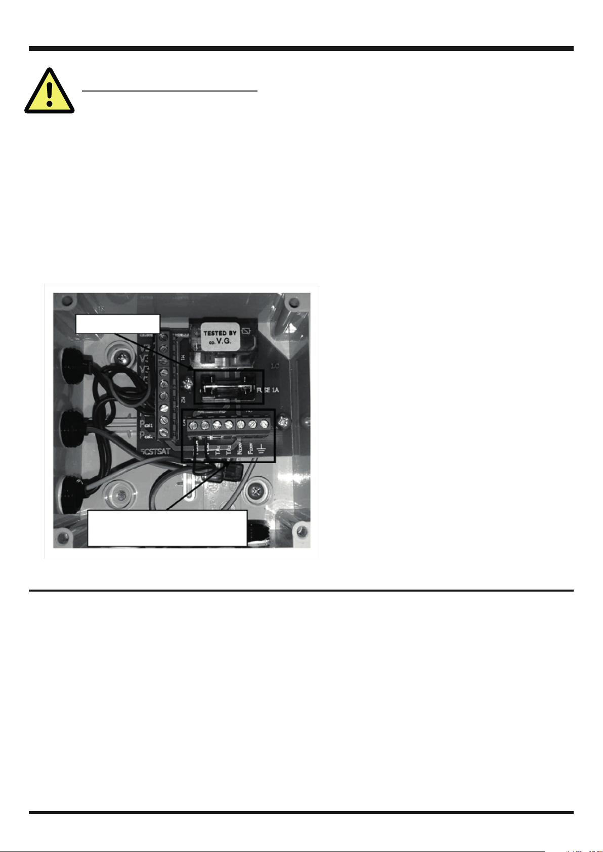
Principal Components............................................................................................................................ 4
Heat Exchanger Characteristics .......................................................................................................... 5
Flowrate Vs Pressure ............................................................................................................................. 5
04. Important Points.............................................................................................................................................. 6
Safety Warnings ...................................................................................................................................... 6
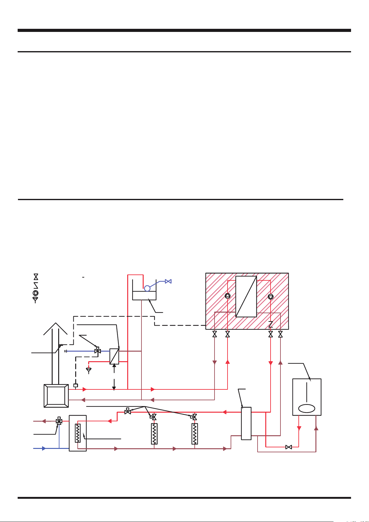
05. System layout .................................................................................................................................................. 7
Fundamental requirements .................................................................................................................. 7
Suggested System Layout ................................................................................................................... 7
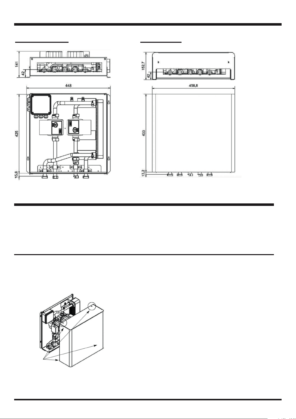
07. Dimensions....................................................................................................................................................... 8
Without Cover .......................................................................................................................................... 8
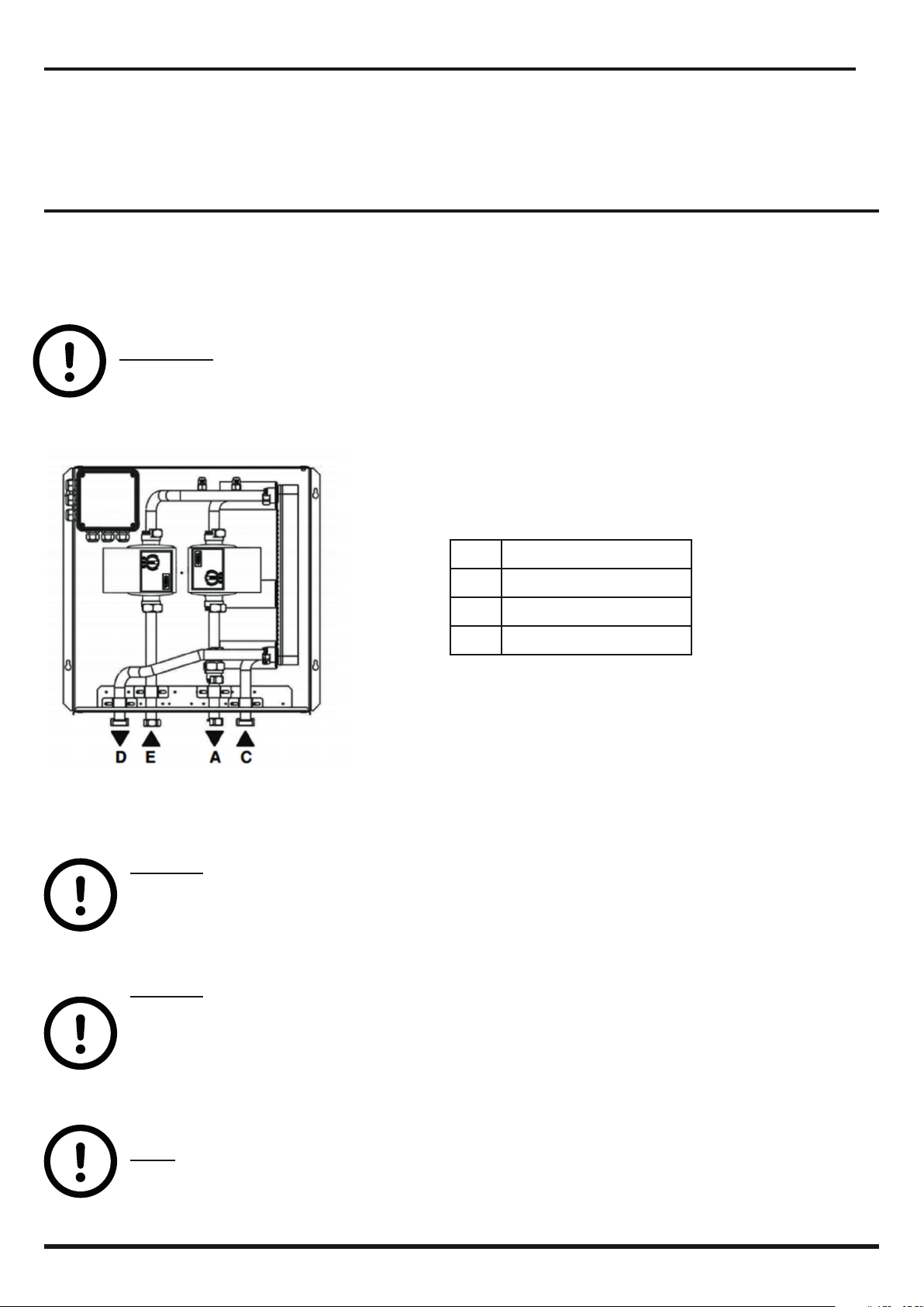
06. Installation ........................................................................................................................................................ 8
Wall Mounting .......................................................................................................................................... 8
With Cover ................................................................................................................................................ 8
Mounting of Flue Thermostat................................................................................................................ 9
Hydraulic connection ............................................................................................................................. 9
08. Electrical connection ...................................................................................................................................10
Power supply .........................................................................................................................................10
Connection to solid fuel boiler ...........................................................................................................11
Schematic...............................................................................................................................................11
09. Commissioning..............................................................................................................................................12
Circulation Control................................................................................................................................12
10. Maintenance and troubleshooting.............................................................................................................13
11. Spare Part List ..............................................................................................................................................13

3
EasyStove Installation, Usage and Maintenance Instructions
Thank you for selecting an EasyStove interface unit. This product is the result of extensive research and experi-
ence in heating system design.
This manual is an integral part of the product and should be retained. Please read it carefully, as it
provides important information regarding the installation and maintenance of the product.
The product should only be installed and maintained by a person qualified in the design and instal-
lation of heating systems. Failure to properly install or maintain the EasyStove product may lead to injury, death
or property damage.
01. GENERAL INFORMATION
1 Heat Exchanger
2 Secondary Circuit Pump
5 Stove Circuit Pump
7 Non Return Valve
A Flow to Secondary System
C Return from Secondary System
D Return to Stove
E Flow from Stove
02. OPERATION
The EasyStove allows the simple and safe integration of a solid fuel stove into a conventional central heating
system, allowing the automatic use of heat from the stove when it is available.
The stove circuit is normally an open circuit operating at atmospheric pressure while a modern central heating
system may be a sealed system operating at a higher pressure. The EasyStove RC provides hydraulic separa-
tion between these circuits via a plate heat exchanger and works equally well in both open and sealed systems.
The EasyStove operates automatically, supplying heat to the heating system when the stove is in operation.
The central heating system is fed with hot water from the gas/oil boiler until the solid fuel boiler has reached a
suitable operating temperature. When this temperature is reached, the stove supplies heat to the central heating
system. If heat is no longer available from the stove, then the stove circuit is switched off.
The recommended method of detecting that the stove is in operation is by using a suitable flue thermostat. A
flue thermostat is supplied with the EasyStove.
WARNING
Carefully read the instructions contained in the manual as they provide important information re-
garding safe installation and maintenance. The installation and maintenance must be performed in
accordance with current standards and according to the manufacturer’s instructions.
In the case of failure or malfunction of the appliance, do not attempt to repair it yourself. Please contact RVR
Energy Technology Ltd by email at info@rvr.ie.
Repairs must be only be carried out by a qualified technicians. Failure to comply with these requirements can
compromise the safety of the device.

4
EasyStove Installation, Usage and Maintenance Instructions
1 Heat Exchanger
2 System Pump
3 Air Vent
5 Stove Circuit Pump
6 Electrical Box
7 Non Return Valve
8Cover
A Flow to System
C Return from System
D Return to Stove
E Flow from Stove
03. TECHNICAL INFORMATION
Stove Circuit
Fluid Type Water
Max. Temperature 90°C
Max Operating Pressure 6 bar
Secondary Circuit
Fluid Type Water
Max Temperature 90°C
Connections
Material Brass
Size 3/4”
Casing and Cover
Material Galvanised Steel
Colour RAL9010
Power Supply
Voltage 230V
Frequency 50Hz
Power 100 W
Protection IP56
Environmental
Installation Location Indoors
Ambient Temperature 5 - 55°C
Ambient Humidity 25 - 85% RH
Weight incl. Cover 11.0 kg
PRINCIPAL COMPONENTS

5
EasyStove Installation, Usage and Maintenance Instructions
HEAT EXCHANGER CHARACTERISTICS
The EasyStove is designed for use with solid fuel stoves with a combustion output* of up to 20kW (max output to
water* of 14kW)
Residual Head (m)
Secondary Connections - Connections A - C
Residual Head (m)
* The combustion output of the boiler/stove is the amount of heat generated by combustion.
** The output to water is the portion of the stove/boiler output that is transferred to water.
FLOWRATE VS PRESSURE
Kvs = 2.5
Primary Circuit - Connections D - E
At Nominal Capacity Primary Stove Circuit Secondary Heating Circuit
Flowrate L/h 800 700
Temperature °C IN/OUT 80/65 55/72

6
EasyStove Installation, Usage and Maintenance Instructions
04. IMPORTANT POINTS
The water connections are on the bottom of the unit.
The 230V, 50Hz power supply must be protected by a suitable MCB.
A flue thermostat must be mounted on the solid fuel boiler/stove and connected as a volt-free contact to the
EasyStove. The ESBE CTF150 model flue thermostat is supplied with the EasyStove.
SAFETY WARNINGS
INCORRECT SYSTEM DESIGN HAZARD!
System design and installation should only be undertaken by skilled and experienced professionals
and in accordance with all relevant regulations. These include but are not limited to the Building
Regulations, IEE regulations and the instructions provided by manufacturers of stoves and boilers.
Incorrect design and installation may lead to unsafe operation resulting in injury, death or property
damage.
ELECTRICAL HAZARD!
The unit contains live equipment. Disconnect the power supply before working on this equipment.
BURN HAZARD!
The equipment may become very hot in normal operation. Do not touch the equipment while in use.
SCALD HAZARD!
Hot water heated by solid fuel stoves may become very hot. A suitable control device such as a
blending valve should be fitted to the domestic hot water supply to ensure that users are not ex-
posed to scalding hot water.
USAGE WARNING
This appliance must be used only for the purpose for which it is intended. Any other use is not
permitted and may be dangerous.

7
EasyStove Installation, Usage and Maintenance Instructions
Easystove
Solid
fuel
stove
Feed/Expansion
Tank
Flow (1"pipe)
Primary
Return (1" pipe)
Primary
Heat
Dissipation Kit
CWM
>=500mm
Waste
Pipe
3
4
*Piping is " unless stated
otherwise
I.V.
NRV
Pump
Tundish
Gas/Oil
Boiler
Motorized Zone Valves
CTF 150
Flue
Therm.
Hydraulic
Header
VTS 100
Water
Heating Tank
Blending
Valve
05. SYSTEM LAYOUT
FUNDAMENTAL REQUIREMENTS
System designers and installers should use their experience, comply with all standards and best practice, and
must ensure that the following fundamental requirements are met:
1. The solid fuel circuit should be “open vented” and fitted with a suitable expansion tank and vent pipe.
2. A permanent heat load, capable of operating in the event of power failure, should be available to dissipate
heat from the solid fuel system and prevent “pitching” to the expansion tank. The EasyStove Heat Dissipa-
tion kit is a good solution for safe heat dissipation.
3. A suitable and approved blending valve must be fitted to the domestic hot water supply to ensure that the
possibility of excessively hot water being delivered to water outlets is eliminated. Hot water may become very
hot when heated by solid fuel. If this is delivered to water outlets, it may cause scalds and burns.
SUGGESTED SYSTEM LAYOUT
The scheme below will suit many systems. It takes account of the fundamental requirements outlined above.
Some stoves and boilers will have a heat dissipation facility but if this is not present, the EasyStove heat dis-
sipation kit should be installed as shown. The heat dissipation kit should be installed on the feed and expan-
sion pipes as indicated. Dimension L should not be less than 500mm and the heat dissipation kit should be
at least 800mm below the expansion tank.

8
EasyStove Installation, Usage and Maintenance Instructions
07. DIMENSIONS
06. INSTALLATION
The EasyStove is suitable for mounting indoors and should be protected from frost. It should be mounted on
a vertical wall capable of supporting the weight of the unit. Leave adequate space around the unit to facili-
tate maintenance operations.
WALL MOUNTING
The EasyStove is normally supplied without a cover. If the unit is equipped with a cover, it should be re-
moved and placed in a safe place. The cover is attached to the frame using four screws, two on the top and
two on the bottom.
WITHOUT COVER WITH COVER
Installation requires no. 4 screws Ø 8mm (not included),
suitable for the type of wall. The position must be selected to
allow easy connection of the pipes to the appliance.
Once you have chosen the position of the unit, confirm that
clearances for service are maintained and that the wall and fix-
ings are robust enough to support the weight of the appliance.

9
EasyStove Installation, Usage and Maintenance Instructions
MOUNTING OF FLUE THERMOSTAT
Ensure that the flue thermostat is firmly and securely inserted in or bonded to the flue pipe.
WATER CONNECTION
The water connections are at the bottom of the unit. Where pipe connections are rigid, flexible connections
may be used to compensate for mechanical and thermal stresses.
IMPORTANT
Isolation valves should be fitted to all connections to facilitate maintenance operations.
All water connections are female threaded with a union in accordance with ISO 228/1 G3 / 4 “F.
CAUTION
Take care when tightening the unit connections to avoid distortion of the copper tubes. Do not apply
excessive torque and support connections adequately.
CAUTION
All units are pressure tested with water. It is possible that seals have suffered a natural volume
reduction due to drying. The installer should check all connections and tighten them if necessary
to restore the compression of the gasket. The installer is responsible for ensuring that the entire
system is watertight.
NOTE
Ensure thorough flushing of the system, to eliminate dirt, before commissioning.
A Flow to System
C Return from System
D Return to Stove
E Flow from Stove

10
EasyStove Installation, Usage and Maintenance Instructions
08. ELECTRICAL CONNECTION
WARNING - ELECTRICAL HAZARD!
Isolate the power supply before performing any work on the equipment.
The electrical installation must be carried out by a qualified electrician. The equipment must be installed
in accordance with IEE and all other relevant regulations.
The EasyStove requires a 230 volts, 50Hz, single phase power supply. The power supply must be protected by
a suitable MCB.
The EasyStove must be earthed in accordance with the IEE Regulations and local codes.
Observe the proper electrical polarity. The method of connection to the electrical supply must facilitate com-
plete isolation and should preferably be made via a fused isolator having a contact separation of at least 3mm in
all poles and supplying the appliance only. The isolator should be located within 1m of the appliance.
FUSE 1A
ELECTRICAL CONNECTION TERMINALS
POWER SUPPLY
The cable supplying the appliance must be a heat resistant type with 3 conductors of minimum CSA = 1.5 mm²
Conductor colours must comply with IEE requirements:
• Neutral - Blue
• Phase - Brown
• Earth – Green / Yellow
Note: a permanent power supply is required for operation of the appliance.

11
EasyStove Installation, Usage and Maintenance Instructions
CONNECTION TO SOLID FUEL BOILER
A heat resistant cable with 2 x 0.75 mm² conductors is required to connect to the flue thermostat of the solid
fuel boiler. The thermostat device must be provided with dry contacts(voltage-free) and be connected to the
terminals TCcom - TCno.
Operation:
Contact TCcom - TCno closed:
The solid fuel boiler/stove is off or not at temperature.
Contact TCcom - TCno opened:
The Solid fuel boiler/stove is at operating temperature
NOTE
On increase of the temperature of the solid fuel boiler/stove, the TCcom -TCno contacts will move from CLOSED
to OPEN.
SCHEMATIC
ESBE CTF150 Flue Thermostat
2. N/C contact max.16(2.5)A, 230VAC
4. N/O contact max.6.3(2.5)A, 230VAC
V31
V32
TCcom TCNO TA1 TA2
V33
V34
V35
Fuse 1A
14
2
Pcam1
Pcam2
Pcal1
Pcal2
E
L
N
RELE
Solid Fuel
Stove

12
EasyStove Installation, Usage and Maintenance Instructions
09. COMMISSIONING
Before operating the equipment, ensure that all air is purged from the EasyStove using the appropriate manual
air vents and that the pump impeller of the pump is free to rotate. Ensure that all air is purged from the EasyS-
tove Heat Dissipation kit (if used). The presence of air in the primary stove circuit will prevent normal circulation.
Once the installation is complete and after checking that all of the electrical and hydraulic connections are cor-
rect, the unit can be started by switching on the power supply.
CIRCULATION CONTROL
Set the pump control to match the type of system. In most cases, the Δp-c operating mode is a good choice.
Operating mode: Δp-c
The electronic control maintains a constant differential pressure generated by the pump at the set-point Hs.
Operating mode: Δp-v
The electronic control varies the set-point of the differential pressure to maintaining linear pump operation be-
tween Hs and ½Hs
Air Purging Function:
An integrated purging function alternates high and low speed pump operation for 10 minutes after start up.

13
EasyStove Installation, Usage and Maintenance Instructions
10. MAINTENANCE AND TROUBLESHOOTING
Maintenance and repair work must be performed by experienced technicians only. Disconnect the
power supply before carrying out any work on the equipment.
The EasyStove must be inspected annually to ensure correct operation and the absence of leaks. A record of
the annual inspection should be preserved.
Troubleshooting:
Problem Solution
No Circulation • Check that the unit is properly connected
Check operation of the circulation pumps
• Check for obstructions in the system
• Clean any filters
Heat Exchange does not occur when
TCcom - TCno contact is open
• Check the electrical connections to the unit
ensuring that the polarity is correct
• Check the circulation pumps
The stove boils even though the power
is connected to the EasyStove
• Check that the flue thermostat is installed properly and has a
good contact with the flue pipe
• Check that the Flue Thermostat is set correctly. A temperature of
about 150°C is usually satisfactory
• Check that the normally closed contacts of the flue thermostat are
connected
• Check that the pumps are running and the speed is set correctly
• Check if the Stove output is exceeds the specifications of the
EasyStove
11. SPARE PART LIST
A RVCIES
B RFSFIATO18
C RFSCAM14S
D RFCIRCYP
E RVFN34MF

Contact us:
RVR Energy Technology Limited
Kenmare
Co. Kerry
V93 F386
Ireland
Sales direct line: +353 (0)64 6689522 Email: sales@rvr.ie
Table of contents