RVR Solar Closet 300 PS Setup guide

Closet 300 PS Unit
Installation, Usage and Maintenance Instructions
20171206
Water pressurisation unit

2
Closet 300 PS Unit Installation, Usage and Maintenance Instructions
Thank you for selecting an RVR Energy Technology product. This product is the result of extensive research and experi-
ence in water pressurisation. This manual is an integral part of the product and should be retained. Please read it careful-
ly, as it provides important information regarding the installation and maintenance of the product.
The product should only be installed and maintained by a person qualied in the design and installation of
water pressurisation systems. Failure to properly install or maintain the product may lead to injury, death or
property damage.
01. INTRODUCTION
This document contains instructions for the use and maintenance of the Closet 300 PS unit. The Closet 300 PS has been
designed to pump clean water not containing abrasive particles.
Before installing and using the Closet 300 PS, read the following instructions carefully. RVR Energy Technology declines
any responsibility in case of accidents or damage caused by improper use of the unit or due to negligence or lack of ob-
servance of the instructions contained in this booklet or use of the product under conditions outside of the rated specica-
tions.
The Closet 300 PS is suitable for the provision of a pressurised water supply in residences and commercial premises. It
contains the following:
A MULTI-IMPELLER SUBMERSIBLE PUMP which is suitable for use in appli-
cations with up to 40 start/stop cycles per hour. The pump is tted with a
continuous duty asynchronous motor and thermal overload protection.
A PRESSURE CONTROLLER which controls the starting and stopping of the
pump. It must be installed in a vertical position with the water inlet at the
bottom and the water outlet at the top. It starts the pump when the outlet
pressure falls below 1.2 bar and stops when the flow stops.
A 300 LITRE TANK INCLUDING FLOAT VALVE AND OVERFLOW. The tank
is manufactured from WRAS approved material and comes with recessed
handles for ease of lifting during installation.
PERFORMANCE
Flowrate (l/min) 10 20 30 40 50 60 70 80
Pressure (bar) 3.4 3.1 2.9 2.5 2.1 1.7 1.2 0.7
Remove the pump
assembly from the
packaging
Insert the pump assembly
into the tank via the top
mounting hole
Ensure that the top plate
is sitting correctly within
the vibration isolating
insulation
Read these instructions
thoroughly before
installing the unit
02. ASSEMBLY

3
Closet 300 PS Unit Installation, Usage and Maintenance Instructions
The Closet 300 PS is supplied with a 3 core mains cable with a length of 2 metres. A 220/240V 50Hz single phase supply
with neutral and earth is required. All wiring must comply with l.E.E. and all local, national and EU requirements. THIS
APPLIANCE MUST BE EARTHED.
Pump Model Motor Power Rated Current Minimum Fuse Size
Diver 6-700 M-A 0.65kW 3.8A 6A
The method of connection to the electricity supply must facilitate complete isolation and should preferably be made via
a fused isolator having a contact separation of at least 3mm in all poles and supplying the pump circuit only. The fused
isolator should also protect the cable supplying the unit.
A fuse/MCB suitable for the protection of motor loads should
protect the circuit to which the pump is connected. The instal-
lation of a ground fault interrupter / RCCD-protector is strongly
recommended.
Cable extensions should only be made with a safe and water-
proof system. The system should be interconnected as shown
in the diagram (L: Brown N: Blue E: Green/Yellow ) using suitable
cable with a cross section of at least 1.5mm2.
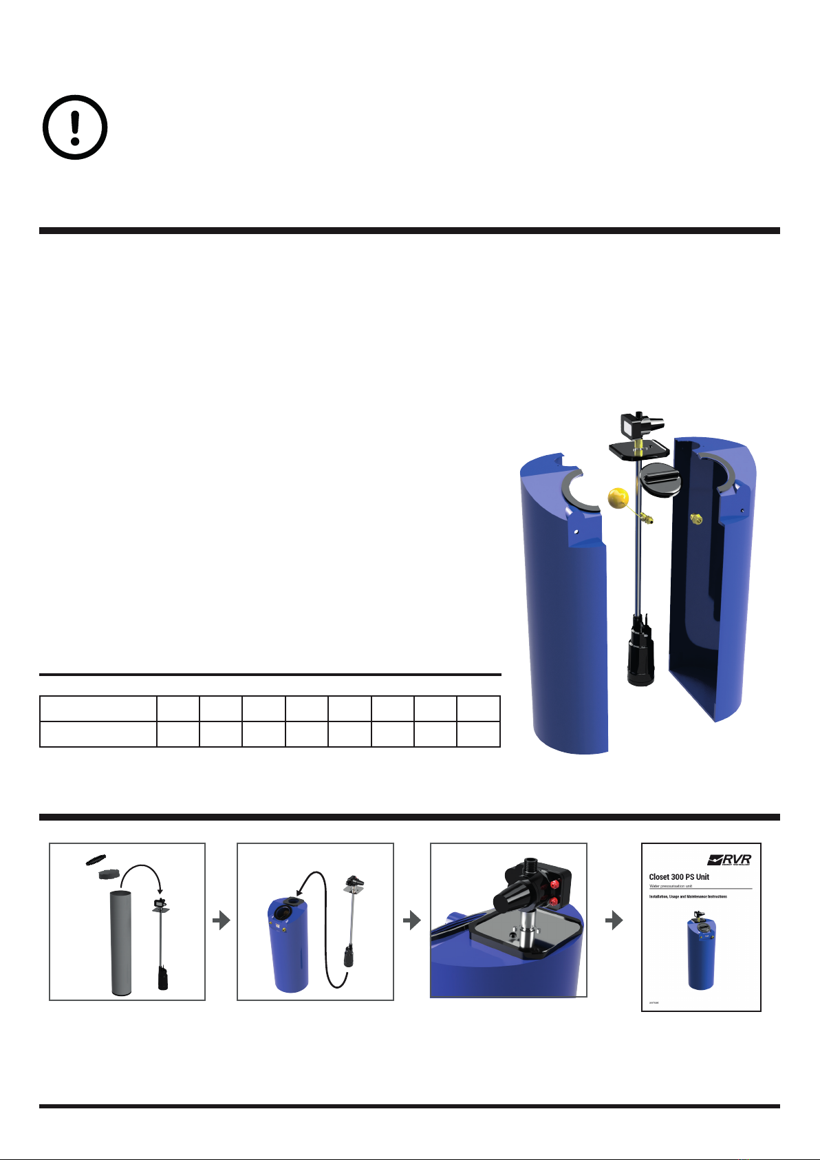
Note - the pump connection (indicated in shaded area) comes
pre-connected on Closet 300 PS.
03. INSTALLATION AND CONDITIONS OF USE
This product must be installed subject to the following limitations:
▪Temperature of pumped liquid between 0ºC and +35ºC
▪Voltage variation allowed +/-5%
▪Maximum number of starts per hour : 40
▪Maximum water column between controller and highest water outlet: 6m
▪Minimum positive head level: 100mm
▪The pump is not suitable for pumping inflammable liquids or for use in locations where
there is a danger of explosion
▪The pump is not suitable for use in swimming pools or garden ponds
▪Do not cover or place anything on top of the controller
Install the Closet 300 PS unit in a dry location, indoors. Vibration isolating material
should be installed underneath the unit. The unit must be installed in a vertical
orientation, otherwise the pump will not operate correctly or leaks may occur.
Make sure that the water is free from sand, grit and other dirt. Do not run the
pump without water. The controller will stop pump operation when there is no
water and will need to be reset when this occurs.
The installer must pressure test the water system fully to ensure there are no leaks before connecting and starting the
pump for the rst time. The maximum pump pressure is 3.5 bar. The pressure test should be carried out at a pressure of
at least 5 bar. Failure to ensure the integrity of all pipework, joints and ttings may result in flooding and property damage.
RVR Energy Technology accepts no liability for damage due to leaks either inside or outside the product.
We recommend the installation of a small (5 litre) expansion vessel on the cold water outlet, which will result in reduced
pump operating cycles and also eliminate frequent starting due to drips and leaks. This will prevent premature failure due
to frequent cycling. If an expansion vessel is installed, the expansion vessel charge pressure should be set to 1.5 bar with
no water pressure in the system. The system will operate satisfactorily without an expansion vessel provided the number
of start/stop cycles does not exceed 40 per hour.
We recommend the installation of an isolation valve on the pressurised outlet. A suitable flexible hose or connector should
be used to connect the Closet 300 PS to the pipework.
COLD WATER
INLET
OVERFLOW
PRESSURISED
OUTLET
04. ELECTRICAL INSTALLATION

The controller has a green Power on light, a yellow Pump On light and a red Failure
light. The green Power On light indicates that a voltage is connected to the control-
ler. The yellow Pump On light indicates that the pump is running.
When the power supply is turned on, both the green and yellow lights come on
and the pump is started for a few seconds in order to allow the system to build up
pressure. If the time is not sufcient, press the Restart button until water is coming
out of an open water outlet. The pump will stop and go into Standby mode when
the water outlet is closed. The green light will be lit. The pump is now ready for
automatic operation.
When a water outlet is opened, the pump starts and runs as long as the outlet is
opened. After the outlet is closed, maximum pressure is restored to the system,
the pump then stops and returns to Standby mode.
If there is a shortage of water during operation, the controller stops the pump, protecting it from dry running. Once water
supply has been restored, the restart button may be pressed to restore normal operation. If the reset button is not manual-
ly pressed, the controller will automatically make 10 double attempts to restart over a 24 hour period. If automatic restart
fails, then the reset button will have to be manually pressed.
If the electricity supply fails, the system will automatically restart once the electricity supply is restored.
RVR Energy Technology Limited
Kenmare
Co. Kerry
V93 F386
Ireland
Sales direct line: +353 (0)64 6689522
Email: sales@rvr.ie
05. OPERATING INSTRUCTIONS
Problem Causes or actions
The pump fails to start Check electrical connections
The pump starts but
fails to deliver water
Water column exceeds 6m
The pump starts and
stops frequently
Leak in the system or no expansion
vessel tted
The pump fails to stop Leak in the system or controller not
installed in vertical orientation
The pump jams Water supply problems, check for
dirt or grit
06. WARNINGS
Carefully read the instructions contained in the manual as they provide important information regarding safe installation
and maintenance. The installation and maintenance must be performed in accordance with current standards and accord-
ing to the manufacturer’s instructions.
Failure to ensure the integrity of all pipework, joints and ttings may result in flooding and property damage.
RVR Energy Technology accepts no liability for damage due to leaks or frost damage either inside or outside
the product, or on any components whether supplied by RVR Energy Technology or not. It is the sole respon-
sibility of the installer to ensure the water soundness of the entire system and the environmental conditions in
which the unit is installed.
This product should not be installed in a location where water leakage is likely to cause damage. If it is necessary to in-
stall this product in such a location such as an attic or higher floor of a building, a ‘tanked’, waterproof chamber should
be created underneath to ensure that any potential leaks from the product and associated ttings or pipes are contained
and drained away safely.
Repairs must be only be carried out by a qualied technicians. Failure to comply with these requirements can compro-
mise the safety of the device.
07. TROUBLESHOOTING
Table of contents
Popular Water Pump manuals by other brands

REMS
REMS Calc-Push instruction manual

BUSCH
BUSCH COBRA NC 1000 B instruction manual

Graco
Graco Husky 1040 Instructions-parts list

GORMAN-RUPP PUMPS
GORMAN-RUPP PUMPS PA6C60-4045T FT4 Installation, operation, and maintenance manual with parts list

Grundfos
Grundfos UPS 15-30 130 instructions

Nexto
Nexto X-PUMP quick start guide

Lowara
Lowara e-HM series Installation, operation and maintenance

Oase
Oase Optimax 10.000 operating instructions

KSB
KSB Calio S BMS Installation & operating manual

Riken Keiki
Riken Keiki RP-D58 AC operating manual

Becker
Becker T 4.25 DV operating instructions

Zehnder Pumpen
Zehnder Pumpen MICROBOY operating instructions