Rycom PATHFINDER PLS Series User manual

Manual Part # 030-00113-00
User Manual
Pathfinder Precision Locating System

1.816.353.2100 www.rycominstruments.com
Copyright
Copyright © 2017, 2019, 2020, 2021 RYCOM Instruments, Inc. All rights reserved.
No part of this manual may be reproduced, copied, modified or adapted, without the prior written
consent of the RYCOM Instruments, Inc.
Please feel free to contact RYCOM Instruments, Inc. to request permission for reproduction and use
of this manual for training purposes.

1.816.353.2100 www.rycominstruments.com
General InformatIon
Introduction ...............................................2
Disclaimer of Liability ........................................2
Important Notices ..........................................2
Compliance ..............................................3
Prepare for Use.............................................4
Register Extended Warranty..................................4
Programming Frequencies . . . . . . . . . . . . . . . . . . . . . . . . . . . . . . . . . . . 5
Transmitter Controls and Indicators ............................6
Direct Connect ............................................7
Flexi-Coupler Connection....................................7
Inductive Connection .......................................8
Blind Search ...............................................8
Selecting the Tracing Signal ..................................9
Receiver Controls and Indicators ............................10
PathLink Controls ..........................................11
Locating the Cable or Pipe .................................12
Selecting the Locating Mode ...............................12
Peak Locating Mode.......................................12
Null Locating Mode ........................................13
Left/Right Auto-Gain Mode .................................14
Absolute Signal Strength ....................................14
Gain Change Indication....................................14
Passive 50/60 Hz Locating...................................15
Passive Radio Frequency Locating ...........................15
Passive Rectifier CP Locating ................................15
Push Button Depth .........................................16
Depth Measurement 45 Degree Angle Method ................17
Current Measurement ......................................17
Tilted Magnetic Field Identification ...........................18
Locating a Sonde .......................................19-20
Sonde Depth Measurement.................................20
STAFF Fault Finder Controls ..................................22
Fault Locating...........................................23-25
PATHFINDER PLS Transmitter Specifications.....................26
PATHFINDER PLS Receiver Specifications ......................27
Factory Service............................................28
Warranty .................................................28
Parts List ..................................................29
table of Contents

1.816.353.2100 www.rycominstruments.com
introduCtion
Congratulations on the purchase of your new RYCOM PATHFINDER PLS Series Cable, Pipe & Fault
Locator. The PATHFINDER PLS Locator is specially designed to detect conductors such as buried pipes
& cables. This device may detect buried power cables, CATV cables, gas and water pipes, sewer
lines, telecommunication lines, fiber optic cables with sheath, sondes, inspection camera transmitters.
You have chosen a quality product that is designed for years of field use without the need for annual
or periodic calibration and service.
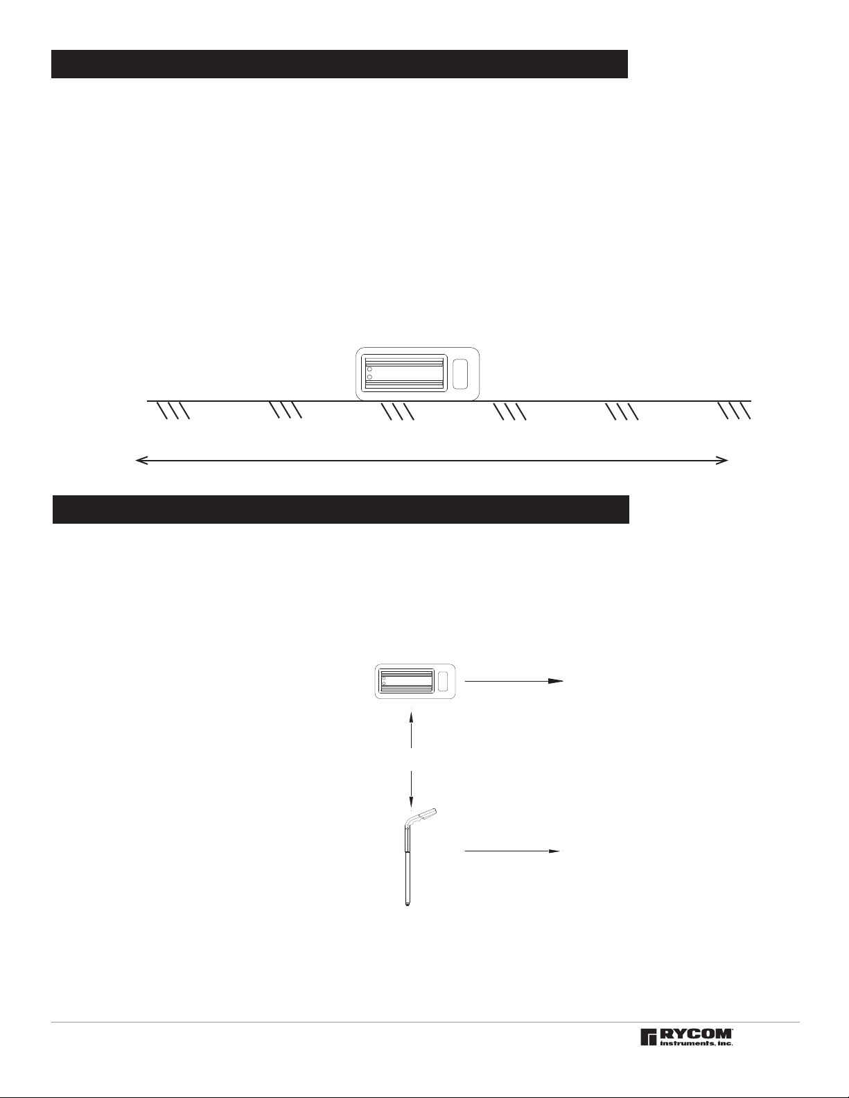
The basic principle of the locator's operation is as follows:
The TransmiTTer emits a signal to a conductive cable or pipe. The receiver detects the
electromagnetic field that is generated by the transmitted signal. You can locate the relative
position of the buried utility by following the tracing signal.
For safely & to help ensure the best locating results, please read & understand the manual in its
entirety before using the product.
RYCOM Instruments, INC shall not be liable to Distributor, Reseller, or any other person for any
incidental, indirect, special, exemplary or consequential damages, or injury of any type whatsoever,
and caused directly or indirectly by Products sold or supplied by RYCOM INSTRUMENTS, INC.
disClaimer ofliability
important notiCes
Failure to follow these warning could result in serious injury or death.
Only persons qualied and trained to operate cable & pipe locators may operate this equipment.
Follow appropriate safety procedure, your companies policies and applicable safety codes and/or
laws.
Do not connect to utilities, cables or pipes without authorization and training.
Use tool only for intended purpose as described in this manual
Do not expose tool to rain or moisture.
Do not expose to hazardous chemicals, hazardous gas or explosive environment.
SHOCK HAZARD - Lethal voltages may be present at the transmitter's output. Turn off transmitter before
touching test lead or any un-insulated conductor. Make connection to ground and target conductor
before turning on transmitter.
SHOCK HAZARD - Do not connect to live voltage or active utility lines. De-energize any circuits in or
around the work area.
This tool is designed to detect electromagnetic eld emitted from cables and buried metallic utilities.
There are buried cables, pipes, and utilities this instrument CANNOT detect.
LOCATING is not an exact science. The only certain way to be sure of the existence, location, or depth
of buried utilities is to carefully expose (dig up) the utility.
WARNING!
WARNING!
WARNING!
WARNING!
WARNING!
WARNING!
WARNING!
WARNING!
WARNING!
WARNING!
WARNING!

1.816.353.2100 www.rycominstruments.com
This equipment complies with Part 15 of the FCC Rules.
Operation is subject to the following two conditions:
(1) The equipment may not cause harmful interference.
(2) The equipment must accept any interference received, including interference that may
cause undesired operation.
This equipment has been tested and found to comply with the limits for a Class A digital device,
pursuant to Part 15 of the FCC Rules. These limits are designed to provide reasonable protection
against harmful interference when the equipment is operated in a commercial environment. This
equipment generates, uses, and can radiate radio frequency energy and, if not installed and used in
accordance with the instruction manual, may cause harmful interference to radio communications.
Operation of this equipment in a residential area is likely to cause harmful interference in which case
the user will be required to correct the interference at this own expense.
Modifications: Any modifications made to this equipment not approved by RYCOM Instruments, inc.
may void the authority granted to the user by the FCC to operate this equipment.
CAN ICES-3(A) Class A Notice:
This Class A digital apparatus complies with Canadian ICES-003.
Avis NMB-003, Classe A:
Cet appareil numérique de la classe A est conforme à la norme NMB-003 du Canada
ComplianCe
fCC ComplianCe statement
industry Canada ComplianCe statements

1.816.353.2100 www.rycominstruments.com
prepare for use
Unpack your new PATHFINDER PLS Locator . Make sure there is no shipping damage and all the parts
are included.
Locate the battery compartment on the back of the of the receiver and on the bottom of the
TransmiTTer.Open the compartments using a Phillips screwdriver. If your unit is a rechargeable system,
remove the terminal isolation paper to allow the battery spring to contact the battery terminal.
If the unit is configured for alkaline batteries, Install the six alkaline Duracell®“C” batteries as marked
in the receiver and twelve Duracell®“D” batteries as marked in the TransmiTTer.
For rechargeable units, please charge for at least 5 hours before use. Remove the terminal isolation
paper inside the battery compartments to allow the battery spring to contact the battery terminal.
Note: For longer battery life and reliable operation under adverse conditions, use only Duracell®
alkaline batteries.
Note: The battery type used must be selected in the programming menu of the transmitter and the
receiver. For instructions on how to select please see page 4.
register extended Warranty
By registering your unit online at http://www.rycominstruments.com/extended.html within one month
(30 Days) of purchase RYCOM will extend the warranty period from one year to 4 years.
This instrument is under warranty for one year from the date of delivery against defects in material
and workmanship (EXCEPT BATTERIES). We will repair or replace products that prove to be defective
during warranty period.
This warranty is void if, after having received the instrument in good condition, it is subjected to abuse,
unauthorized alterations or casual repair.
No other warranty is expressed or implied. The warranty described in this paragraph shall be in lieu of
any other warranty, including but not limited to, any implied warranty of merchantability or fitness for
a particular purpose. We are not liable for consequential damages.

1.816.353.2100 www.rycominstruments.com
Vol
voL 1
vol 2
vol 3
vol oFF
Light
Light
oFF /on
Units
Metric
oFF /on
Orient
Orient
oFF /on
dePth
depth
oFF /on
Curnt
Curnt
oFF /on
Ac Sory
Ac Sory
oFF /on
Vibrtn
Vibrtn
oFF /on
To select the desired frequency set for software versions 3.43 and greater:
• Press and hold depressed the Power onBuTTon.
• Pressing the informaTion BuTTon will toggle through available configurations. Repeat pressing
until 'u5' is displayed in the frequency indicaTor section of the LCD.
• Release the Power onBuTTon.'Pro'will be displayed on the LCD.
• Press the frequency BuTTon to toggle through the available frequencies.
• To select and store the desired frequency press the informaTion BuTTon. The count of the
selected frequency will be displayed on the LCD.
• Continue to toggle through and select the desired frequencies,
• Press the Power onBuTTon to shut the unit off. This will save the selected frequencies for
availability during normal operation.
The PATHFINDER PLS operating modes, frequencies and other functions are user programmable and can
be changed at anytime through a quick selection process in the programming menu.
To select the programming options for software versions up to 3.42:
• With the unit on, press and hold depressed the ProGram menu (Power on) button for 5 seconds. Once
released "Pro"'will be displayed at the top of the LCD.
• To scroll through the programming menu headings, use the uPor Down arrow (GaIn uP/GaIn Down)
buttons.
• To enter a selection's sub-menu use the arrow rIGht (ShIft/loG/DePth) key.
• To exit a selection's sub-menu use the arrow left (frequency) key.
• To scroll through sub-menu options use the arrow uPor arrow Down (GaIn uP/GaIn Down) key.
• To select an item or to toggle between item options, press the Select (moDe)key.
• Pressing the ProGram menu (Power on)button at any time will save the selected options for availability
during normal operation and exit the programming menu.
Changing preset funCtions, modes & frequenCies
reCeiver
transmitter
P-Link
P-Link
oFF /on
dFF
dFF
oFF /on
batt
L,-,on / A1ka
OpMode
W-Pk
oFF /on
W-Pk ><
oFF /on
P-Pk
oFF /on
P-Pk ><
oFF /on
Null
oFF /on
Null ><
oFF /on
LR
oFF /on
Pro
Sonde
512 hz
oFF /on
640 hz
oFF /on
815 hz
oFF /on
1.01 hz
oFF /on
4.10 hz
oFF /on
8 khz
oFF /on
33 khz
oFF /on
116 khz
oFF /on
Line
RF
oFF /on
PWR-50
oFF /on
50Phz
oFF /on
150Phz
oFF /on
250Phz
oFF /on
350Phz
oFF /on
450Phz
oFF /on
CP5
oFF /on
PWR-60
oFF /on
60Phz
oFF /on
180Phz
oFF /on
300Phz
oFF /on
420pHz hz
oFF /on
540Phz hz
oFF /on
CP6
oFF /on
200 hz
oFF /on
256 hz
oFF /on
273 hz
oFF /on
512 hz
oFF /on
570 hz
oFF /on
577 hz
oFF /on
640 hz
oFF /on
760 hz
oFF /on
797 hz
oFF /on
815 hz
oFF /on
833 hz
oFF /on
870 hz hz
oFF /on
920 hz hz
oFF /on
940 hz
oFF /on
1.01 khz
oFF /on
1.02 khz
oFF /on

1.816.353.2100 www.rycominstruments.com
815 Hz
82 kHz
8 kHz
TX OUTPUT
I / O
I
LOADING
FOR INDUCTIVE MODE
PLACE ARROWS ALONG CABLE PATH
8878
I / O
I82 kHz
8 kHz
815 Hz
LOADING
TX OUTPUT JACK
The red/Black cord, Coupler and flexicouPler connects here to create a circuit on the buried utility.
FREQUENCY SELECTOR
This button toggles through the available frequencies. The selected frequency is displayed on the
LCD. When dual frequency transmission options are selected, indicated by the D1 & D2 icons to the
right large numeric segments, the frequencies will flash from one to another.
LOAD INDICATOR (visual & audible)
The Load Indicator symbol flashes to indicate signal output.
The quick triple beep audible tone indicates the circuit is open and no signal is being transmitted.
A steady continuous beep indicates a closed circuit and signal is transmitted . When the indicator
blinks 4 times per second, it is indicating a nearly short circuit. When the indicator blinks 1 time every
10 seconds, it is indicating a nearly open circuit.
OUTPUT SIGNAL LEVEL CONTROL
The OUTPUT SIGNAL LEVEL CONTROL adjusts the power output from the TransmiTTer. There are 5
selections on the standard power setting and 5 selections on the HPO setting. The standard power
output maximum is 30volts. In the HPO setting the maximum voltage is 200volts. Holding down the
Output Signal Level button for 3 Seconds will activate the High Power Output mode.
High Power Output is a SHOCK HAZARD - Lethal voltages at the transmitter's output. Turn off transmitter
before touching test lead or any un-insulated conductor. Make connection to ground and target
conductor before turning on transmitter.
SIGNAL INFORMATION SELECTOR
The unit can display the relative resistance, current and voltage of the transmitted signal. The
resistance is based on the feed back from the selected frequency and is not an actual impedance
meter. The selections can be toggled by pressing the SIGNAL INFORMATION button.
Power On & Off
Tx Output Jack
Frequency
Selector
Battery Condition
Indicator
Load Rate
Indicators
Output Signal
Level Control
Relative
Resistance, Volt,
Current
CAUTION
Lethal Voltages May Be Present
Signal Information
Selector
transmitter Controls & indiCators
Output Level
Indicator
High Power
Output
Indicator
WARNING!

1.816.353.2100 www.rycominstruments.com
direCt ConneCtion
Direct Connection is the most reliable method of signal application. This method is relatively free
of interference. The greatest amount of signal strength can be achieved by this method. Low,
mid, and high frequency may be used. The far end of the utility must be grounded.
Connect the red TesT cord to an existing ground point or an exposed metallic section of the utility
. Place the Ground rod approximately 10 feet from this point, at an angle of 90º to the buried
cable or pipe. Push the Ground rod into the ground 8 to 10 inches. Connect the Black TesT cord
to the Ground rod.
Plug the red/Black TesT cord into the TX OUTPUT JACK. Select the desired frequency. The Signal
Output Indicator will flash once signal is established.
The optional flexicouPler and Hard couPler are very easy to use, and services do not have to
be interrupted. The operation range is shorter than for Direct Connection methods. The tracing
signal can be affected by neighboring cables and pipes. The red/Black TesT cord or the Ground
rod are not needed for this method.
Successful couPler operation requires an insulated conductor that is grounded on both near and
far ends.
Loop the flexicouPler around the cable and connect the two ends, or clamp the Hard couPler
around the cable. It is important to connect the couPler around the cable needing to be traced.
Connect the couPler around the wire closer to the outgoing cable not near the system ground.
The result will be a stronger signal. By connecting near the grounding, the range will also be
shorter, and difficulty may arise determining one cable from another.
Plug the couPler into the TX OUTPUT JACK.
Some couplers are frequency specific others can operate on any frequency from 4kHz to 82kHz.
CAUTION
TRANSMITTER
BLACK
BURIED CABLE
RED
FLEXICOUPLER
BURIED CABLE
TRANSMITTER
DO NOT CONNECT TO LIVE OR
ENERGIZED POWER CABLES
Coupler & flexiCoupler ConneCtion

1.816.353.2100 www.rycominstruments.com
This method is convenient to use, and services are not interrupted. No test cords or connections
are needed. The cable or pipe must have good insulation or non-conductive coating, or the
operating range will be short.
Turn the TransmiTTer ON. Select 33kHz through 478 kHz. Place tranSmItter on ItS SIDe as close as
possible to the path of the cable or pipe. Align the ARROWS on the SIDE OF THE TRANSMITTER
in line with the cable or pipe. First, locate the broad TransmiTTer Null, then move toward the
expected cable path while looking for the signal carried by the cable.
Start tracing the path with the receiver 25 feet from the TransmiTTer. Search in the 90º zone as
shown above. Locate the cable or pipe, and follow the path. If the signal becomes weak, move
the TransmiTTer to a point 25 feet behind the last strong signal, and continue searching.
The Blind Search locating techniques is used if the operator is not aware if a buried utility exists.
Two people are needed for this technique. The TransmiTTer and the receiver are Held 25 feet away
from each other. Each operator walks at the same speed keeping a distance of 25 feet from
each other. When the receiver gives an audio response, then a buried utility is present between
the receiver and the TransmiTTer.
TRANSMITTER
25 Feet (7.5 Meters) Between Transmitter and Reciever
RECEIVER
TRANSMITTER
25 Feet (7.5 Meters) Between Transmitter and Reciever
RECEIVER
induCtive ConneCtion
blind searCh

1.816.353.2100 www.rycominstruments.com
seleCting the traCing signal
The choice of frequency is dependent on the conditions of the locate. It is generally accepted
that lower frequencies provide a more accurate locate. Therefore it is generally advised to use
the lowest frequency that effectively conducts on the target line. Lower frequencies are less
likely to bleed onto adjacent non-target lines, but low frequencies are less effective at locating
higher-resistant conductors.
FREQUENCY RANGES
Frequencies are classified into three major categories, Low, Medium and High and they are
classified as follows:
• Low Frequencies < 1 kHz (1000 Hz) e.g. 512 Hz, 640 Hz, 815 Hz
• Medium Frequencies 1 kHz to 44 kHz e.g. 4 kHz, 8 kHz, 33 kHz
• High Frequencies 44 kHz to 480 kHz e.g. 65 kHz, 82 kHz, 200 kHz
FREQUENCY CHARACTERISTICS
The low, medium and high frequencies each have their advantages. It is recommended to
begin by using a low frequency, and continue as long as you are confident in the results. If the
signal is very weak try to adjust the connection or grounding. If there is no improvement in signal
then try mid-range frequencies. Again, if there is weak or absent signal, repeat adjustments of
the grounding and connection point before switching to a high frequency.
The method of signal application may dictate the frequencies used. While direct connection
can be performed on any frequencies, coupler induction will only work with medium and high
frequencies and transmitter induction will only work on the highest of the medium frequencies
(33kHz) and high frequencies.
Low Frequencies are usually preferred to the mid-range frequencies and high frequencies
because they are less susceptible to locating errors caused by coupling of signal to adjacent
conductors, cables or pipes. The low frequency locating range is also much longer than the
medium and high frequencies. Low frequencies will not travel well on highly resistive lines
or conductors that have interruptions in their continuity (e.g. disconnected shield bonds or
insulated pipe bushing). Low frequencies may only be applied via direct connection.
Medium Frequencies take the best of both high and low frequencies. Medium frequencies are
not as susceptible to bleed off or coupling as the high frequencies, and medium frequencies
can jump minor breaks in continuity and conduct on higher resistant lines better than low
frequencies. It is still best to use low frequencies whenever effective, but 8 kHz and 33kHz are of
the most common frequencies used in locating. Medium frequencies may be applied via direct
connection and via coupler induction [Note: 33kHz may be applied via transmitter induction].
High frequencies are sometimes better than the low frequencies for locating highly resistant
lines as well as conductors that have breaks in their continuity (e.g. disconnected shield bonds
or insulated pipe bushing). The locating range is quite short for the high frequencies so the
TransmiTTer must be repositioned more often during the tracing operation. High frequencies may
be applied via direct connection, coupler induction and transmitter induction.

1.816.353.2100 www.rycominstruments.com
ON/OFF Button
The unit will load settings from previous usage. Automatic shut off after 10 minute of no use.
FREQUENCY Button
Toggles through available selected active and passive frequencies.
Note: Some frequencies are only available in certain modes and some modes will only be
available with certain frequencies. The available selectable frequencies can be edited within the
programing menu.
MODE Button
Toggle through available modes. PEAK, PINPOINT PEAK, NULL, LEFT/RIGHT, and SONDE locating
modes.
Note: The available selectable modes can be edited within the programing menu.
SHIFT, LOG, DEPTH, P-Link Button
This key's function changes depending on the features turned on within the programming menu.
Under normal operation the SHIFT/DEPTH/LOG Key will force take a digital depth reading and, when
used with data logging, send locate data to a GPS or data logger.
When used with the P-Link communication between the transmitter and the receiver the SHIFT/
DEPTH/LOG Key will trigger the sending the selected frequency to the transmitter.
GAIN Button (Up or Down)
Adjusts the gain up or down. If the graph shows signal strength off scale, pressing the GAIN will
automatically adjust to 50% on the scale display.
pathfinder pls reCeiver Controls & indiCators
ABSOLUTE SIGNAL STRENGTH
DEPTH
RELATIVE SIGNAL
STRENGTH BAR GRAPH GAIN LEVEL INDICATOR
Left Right Guidance
Displays direction to
null point of e.m. field.
ANTENNA LOCATE MODE
Displays selected
antenna mode.
DISPLAYS SELECTED
FREQUENCY
BATTERY LIFE
Displays receiver's
battery life.
OPERATION MODE
Displays selected
operation mode
PathLink
Displays remote
connection to
transmitter &
transmitter output
power.

1.816.353.2100 www.rycominstruments.com
Changing the transmitted frequency with PathlInk
Select the desired active frequency by pressing the Frequency key. Once the
desired frequency is selected, pressing the ShIft/loG/DePth button will remotely
select the frequency on the Transmitter. The icon of the transmitter will flash
momentarily then becoming solid confirming the selected frequency has been set
at the transmitter. If the transmission is incomplete or if the frequency requested is
not available, then the symbol will continue to flash.
Changing the transmitted power with PathlInk
To increase or decrease the transmitted power output, simply press and hold
depressed the ShIft/loG/DePth key while pressing either the GaIn UPor Gain Down key
to increase or decrease the power output level. The power indicator icon on the
receivers PathLink section of the LCD will display accordingly indicating the power
out level.
Note: In P-Link mode the manual digital depth engaged by the ShIft/loG/DePth key is disabled
and the automatic depth function is enabled.
Turning On and Off PathlInk
·To turn on the remote control feature, PaTHlink,start with the unit on.
·Press and hold depressed the Menu button (Power on/off)for 4 seconds.
·"Pro" will display at the top of the LCD.
·Using the uPor Down (GaIn uP/ GaIn Down) menu keys scroll to "P-Link".
·Use the arrow rIGht (ShIft/loG/DePth) key to select the P-Link Menu.
·Press the menu Select button to select P-Link "on".
·Exit the Programming Menu by short press of the menu button or arrow left (frequency)to
make other programing selection.
·In a moment the PathLink Indicator will be displayed on the receiver LCD indicating the
unit has linked with the transmitter.
pathlink Controls
The optional PaTHlink feature enables the user to remotely control the transmitter with the
receiver. The frequency and power output of the transmitted signal can be controlled up to 800
meters (874 yards).
If your unit does not have the PathLink module, the program will not allow the menu to select
the option on.

1.816.353.2100 www.rycominstruments.com
If you rotate the receiver while over the cable, a sharp NULL will identify the cable’s direction. It
is aligned with the flat side of the receiver.
CABLE
PATH
MAXIMUM
RECEIVER
SIGNAL DIRECTION
CABLE
NULL SHOWS
PATH
CABLE
peak mode loCating
Peak and Pin Point Peak modes have less error rates than the null locating mode in most
circumstances. The peak mode location indication should be verified by the null to ensure
locating accuracy.
With the receiver in a vertical position. Move the receiver left to right across the path. When the
receiver isdirectly abovethe cableor pipe,rotate thereceiver for amaximum signal.As youmove the
receiver away from the cable path, the meter reading (and audio frequency response) will drop off.
The Left/Right arrows operate off of the Null reading. By utilizing the Left/Right arrows while in
Peak mode the user can simultaneously locate in both modes thus quickly identifying the match
or discrepancy between the Peak and the Null reading.
loCating modes
There is a variety of locating modes available in the PATHFINDER PLS unit. PEAK, PINPOINT PEAK,
NULL LEFT/RIGHT GUIDANCE, SONDE, DFF & ACC. To toggle through PEAK, PINPOINT PEAK &
NULL simple press the mode button. To toggle to SONDE mode hold the MODE button for 5
seconds and release. DFF and ACC modes are only selectable when an appropriate accessory
is plugged into the accessory port in the handle of the receiver.

1.816.353.2100 www.rycominstruments.com
If you can no longer trace the path, even with the GAIN set to maximum, connect the TransmiTTer
to the far end of the path and trace back to the point where you lost the signal.
Mark the straight sections of the path every few feet. Mark sharp curves, loops, and cable
bundles every few inches. Sharp changes in the path cause the receiver'sPEAK and NULL
indications to behave differently than when tracing a straight path. Practice on the path that
you know has turns and laterals in it. This will help you to recognize the conditions within the
field.
Trace the path by walking away from the TransmiTTer at a moderate pace. Move the receiver to
the left and right while walking, following the PEAK indications.
Asyoutracethepath,thePEAKmeterreadingmayslowlyfadeasyoumoveawayfromtheTransmiTTer.
Press and release the GAIN buttons as needed to compensate for changes in level (higher or lower).
One of the following may have occured at areas of detected signal loss:
a) a junction where the signal divides and goes several directions.
b) a break in the cable or shield.
c) a change in the depth of the cable or pipe.
d) an insulated pipe fitting.
e) a slack loop of cable.
Move the receiver left to right across the cable path. When the receiver
is directly above the cable or pipe, a NULL (lowest meter reading and lowest audio
tone) will occur. When moving the receiver to left or right of the NULL point, the
meter reading will rise to a maximum point (PEAK). The audio tone will also be at its
highest pitch. When the receiver is moved beyond the PEAK, the meter reading will begin to
fade.
Trace the path by walking away from the TransmiTTer at a moderate pace. Move the receiver to
the left and right when walking, following the NULL indications.
It is expected that in areas of distortion and interference the Null locating mode will have a
greater error rate than the Peak locating mode.
null mode loCating
Null Mode
Buried cable
Buried cable
Signal over cable
Peak Mode
(End view)
Receiver Max
(End view)
Receiver Min
Signal over cable

1.816.353.2100 www.rycominstruments.com
The PATHFINDER PLS receiver provides the operator with a direct measurement of the receiver’s
signal strength. The measurement is displayed with three numerical digits (ex: 485) located at the
top of the LCD display. The measurement range is from 0 to 999 indicating a very week signal
(0) to a very strong signal (999). Absolute Signal Strength is independent of the GAIN setting
or meter reading. It gives the operator information about the actual amount of signal being
radiated from the conductor and received by the receiver.
Measuring Absolute Signal Strength at any time is done by reading the number at the top of the
LCD display. The Absolute Signal Strength will not be displayed if the meter reading is too high
or too low. Adjust the GAIN to move the meter reading to mid-scale. The numerical display will
change from ‘---’ to a valid measurement.
Absolute Signal Strength measurements are more sensitive to signal changes than the meter
display. PEAKS and NULLS can be more precisely pin-pointed. This measurement can also be
used to monitor signal loss as the conductor is being traced.
The GAIN up and down buttons are used to increase and decrease the gain in small amounts.
If the meter reading is very low, pressing the GAIN up button will center the meter reading to
mid-scale. Likewise, if the meter reading is very high, pressing the GAIN down button will center
the meter reading to mid-scale.
absolute signal strength
gain level indiCation
In this mode the unit will display directional arrows to the
conductor. The audio indicator will provide a solid tone
on one side of the conductor and a pulsed tone on the
opposite side of the conductor. When the unit is centered
in the electromagnetic field the tone will null and the depth
will briefly display at the top of the LCD. This mode is gain
independent.
The Left/Right arrows operate off of the Null reading and will
have the same error rate as the Null locating mode. By utilizing
the Left/Right arrows with the absolute signal strength reading
the user can simultaneously locate with both Peak and Null
modes, thus quickly identifying the match or discrepancy
between the Peak and the Null reading.
left right auto gain direCtional loCating

1.816.353.2100 www.rycominstruments.com
The PATHFINDER PLS receiver is capable of locating power utility frequencies. This MODE is useful
for locating underground primary and secondary power utilities. In certain circumstances, this
MODE will also locate water pipes, sewer lines, cable television, and telephone. The reason is
that common electrical grounds are sometimes found among these various utilities. Select 50Hz
or 60Hz frequency on the receiver. PINPOINT PEAK mode will automatically be selected as the
preferred method to locate the conductor in passive power mode.
This method is useful because of its speed and convenience. Start at a known reference point
and keep in mind that other conductors in the area may produce this same locating signal.
The TransmiTTer is not required to locate in this mode.
Note: The unit of depth measurement determines the selection of either 50Hz or 60Hz passive
mode. The unit is configured for 50Hz when in Metric Measurement mode and 60Hz when in
English Measurement Mode. To change unit of measurement press and hold the frequency
button for 10 seconds, when released the unit will toggle measurement units.
The PATHFINDER PLS receiver is capable of passively locating metallic utilities where radio
frequencies have coupled to the utility. This mode is useful for sweeping a green area for
utilities. In certain circumstances, this mode will locate water pipes, cable television, gas lines
and telephone. This locating option does not always detect buried utilities even when radio
frequencies are present. This method is useful because of its speed and convenience. Start at
a known reference point and keep in mind that other conductors in the area may produce this
same locating signal.
The TransmiTTer is not required to locate in this mode.
passive 50/60 hzloCating
passive radio frequenCy loCating
The PATHFINDER PLS RECEIVER is capable of locating the rectified signal of Cathodically Protected
utilities at 120Hz and 100Hz. This method is useful because of its speed and convenience. Start at a known
reference point and keep in mind that other conductors in the area may produce this same locating signal.
Note: The unit of depth measurement determines the selection of either 100Hz or 120Hz passive mode.
The unit is configured for 100Hz when in Metric Measurement mode (for 50Hz power) and 120Hz (for
60Hz power) when in English Measurement Mode. To change unit of measurement press and hold the
frequency button for 10 seconds, when released the unit will toggle measurement units.
The TRANSMITTER is not required to locate in this mode.
passive reCtifier Cp loCating

1.816.353.2100 www.rycominstruments.com
The only way to be sure of the depth of a utility is to exposes the utility.
At any given time, the depth readout may be inaccurate.
The PATHFINDER PLS Receiver can perform digital depth measurement. The depth is dis-
played at the top of the LCD display in centimeters or feet and inches. Push button depth is
useful in quickly estimating the depth of the conductor during path locating.
Begin this measurement by locating the path of the cable or pipe. Stay at least 15 feet (4.6
meters) away from the Transmitter. Pin-point this location as accurately as possible (see Peak
Mode Locating page 19, Null Mode Locating page 20 and Absolute Signal Strength page 21).
Place the Receiver vertically over the conductor and rest the foot of the locator on the ground.
While holding the Receiver vertical, press and release the DEPTH button. The Receiver will
briefly indicate a measurement is being performed and then display the depth at the top of the
LCD display.
Caution must be exercised when using the push button depth feature, as tilted magnetic fields
and adjacent conductors can significantly influence this measurement. The operator should
periodically check for adjacent conductors and tilted magnetic fields when taking push button
depth readings. For information on identifying tilted magnetic fields, refer to Tilted Magnetic
Field Identification and Depth Measurement 45º Method.
Depth is determined by reading the electromagnetic field radiating from the conductor. The
field must be even and circular for the most accurate reading. Interference of this field may be
caused by bends in the cable, faults on the target conductor and signals radiating from adja-
cent non-target conductors. Interference will warp the field and skew the depth reading. The
only way to be sure of the depth of a utility is to expose the utility. At any given time, the depth
readout may be inaccurate.
The following are methods and procedures that will aid in increasing the reliability and testing
the accuracy of the depth reading:
• Take depth readings at least 5 yards from cable bends or depth changes. Follow the
cable both forward 5 yards and backward 5 yards, ensuring the line is straight and
there is a consistent signal strength reading.
• Check for non-target conductors within 5 yards of the target cable. Sweep the
area looking for coupled signals into both the tracks and adjacent cables. Adjacent
conductors carrying the locate signal can result in a 50% error rate of the depth
reading.
• Test for interference in the magnetic field by comparing the PEAK location to the Null
location. The determined cable position by these methods should be within 3 inches of
each other. A greater disparity will indicate interference resulting in inaccurate depth.
• Place the receiver vertically over the conductor and perpendicular to the conductor.
Rest the foot of the locator on the ground. Take several depth readings moving slightly
across the perpendicular plane to the conductor looking for the lowest depth reading.
• Once the lowest depth reading is found, take several readings. Each reading should be
within one inch of the other reading. Wider variation will indicate interference resulting
in inaccurate depth.
• Lift the receiver up 12 inches and take a depth reading. The reading should reflect the
change in distance accordingly. If not, interference is present resulting in inaccurate
depth.
• Verify the depth reading using the triangulation method as described below:
· Mark the path on the ground as precisely as possible using the Null method.
· Place the Receiver on the ground with the LCD meter facing up. Position the unit
so that the Bubble Level on top of the meter is centered (45º).
· Pull the Receiver away from the cable path (at 90º to the cable path) keeping the
Bubble Level centered.
· When the receiver indicates a Null reading, mark the location of the receiver’s foot.
· The distance between the Receiver and the cable path is the depth of the pipe or
cable. A false depth reading may be caused by nearby buried metallic objects, such
as a second cable, pipe, sewer, fence or railroad track.
· Confirm the depth measurement by repeating the above steps on the opposite side
of the pipe or cable.
· A variance greater than 5 inches in depth measurement may indicate interference
from adjacent cables, pipes or other objects.
push button depth
DE PTH R EA DI NG
EP TH R EA DI NG (A + 12" )
LIF T 12"
Buried cable or pipe
Earth
locate
Path 1st
Null
Null
centered
Bubble level
2nd
(end view)
Depth
Depth
45°
D
(A )
• Peak & Null readings match
• From the Peak/Null location take several
readings across cable.
• Mark position indicated by lowest depth reading.
• While stationary take multiple depth readings.
• Reading should be consistent.

1.816.353.2100 www.rycominstruments.com
The PATHFINDER PLS receiver contains a feature that is very useful in identifying a desired cable in
a field of various conductors and/or utilities. It is not unusual for the target conductor (the con-
ductor connected to the transmitter) to induce a signal into nearby conductors in a crowded
field. In these instances, the radiated signal on the conductors close to the surface of the earth,
may be stronger than the TransmiTTer signal on the target conductor buried deep in the ground.
The operator will find two or more paths and must determine which is the target conductor. By
using the current measurement feature of the PATHFINDER PLS receiver, the operator can deter-
mine the amount of 815 Hz, 8 kHz, 33kHz or 82 kHz current flowing on the conductors, regardless
of the depth. The highest current flow indicates the target conductor.
Place the receiver vertically over one of the conductor marks and rest the foot of the locator
on the ground. Holding the receiver vertical, press and release the Shift Button & Depth button
simultaneously. When the meter changes from a “thermometer” type display to a “bar” type
display, hold the receiver still until the measurement stabilizes. The blinking bar indicates the
signal level on the cable (adjusted for depth). Next, move to the second cable and repeat
the measurement. The blinking bar will show the signal level on the conductor. In addition, the
previous reading is shown as a solid bar. The higher of these two readings will show which con-
ductor is carrying the greatest locating signal.
Current measurement
Move to the location you want to measure depth. Stay at least 15 feet away from the TransmiTTer.
Move the receiver left to right across the path until the cable is located. Mark the path on the
ground as precisely as possible using the Null Method.
Place the receiver on the ground with the LCD meter facing up. Position the unit so that the
BUBBLE LEVEL on top of the meter is centered (45º). Pull the receiver away from the cable path
(at 90º to the cable path) keeping the BUBBLE LEVEL centered. When the receiver indicates a
NULL reading, mark the location of the receiver’s foot. The distance between the receiver and
the cable path is the depth of the pipe or cable.
A false depth reading may be caused by nearby buried metallic objects, such as a second
cable, pipe, sewer, fence or railroad track. Confirm the depth measurement by repeating the
above steps on the opposite side of the pipe or cable.
A variance greater than 5 inches in depth measurement may indicate the presence of
additional buried cables, pipes or other objects.
Buried cable or pipe
Earth
locate
Path 1st
Null
Null
centered
Bubble level
2nd
(end view)
Depth
Depth
45°
depth measurement 45º angle method

1.816.353.2100 www.rycominstruments.com
When adjacent cables or pipes are present, they will sometimes create locating errors. Some
of the Transmitter signal is picked up by the adjacent conductors and is redirected so that it
combines with the original signal. The result is a Tilted Magnetic Field. This is often the reason
that numeric depth readouts are sometimes created in error.
The operator can verify the accuracy of path locate by performing a variety of tests.
• The 45º Angle Method locate on both sides of the cable path. If the right and left
side depth readings agree to within 5 inches, the path locate is accurate. If the two
depth readings do not agree, then dig with care. A closer locate would be halfway
between the two outside depth locate marks.
• Test for interference in the magnetic field by comparing the PEAK location to the
Null location. The determined cable position by these methods should be within 3
inches of each other. A greater disparity will indicate interference resulting in inac-
curate depth.
NOTE: The Left/Right arrows operate off of the Null reading. By utilizing the Left/Right
arrows while in peak mode the user can simultaneously locate in both modes thus
quickly identifying the match or discrepancy between the Peak and the Null read-
ing.
These are important techniques that should be used to ensure the most accurate location
possible.
skeWed magnetiC field identifiCation
Table of contents