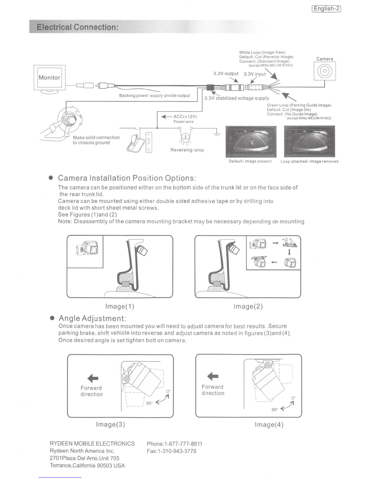
Rydeen CM-R100 User manual

[English-1)
'---EN®
find
your
road
Re11erse
Aid
Camera
Owner's
Manual
Modei:CM-R100
Modei:CM1-T150B-PR
Modei:CM3-T150B-PRI
Modei:CM2-T150B-PR
HD
'
-.
~1~~
'
.~~~
~
J.~
Model
CM-R100
I
CM1-T150B-PR
I
CM3-T150B-PRI
CM2-T150B-PR
HD
Current Consumption MAX:100mA
Power Supply
DC
9-16V
Sensor IC CMOS-IV,
1/4
Ultra CMOS II
Effective Pixels 648(H)x488(V) 728(H)x488(V)
TV System NTSC
Video output Color video out: 1.0Vp-p75(ohm)load
Resolution 480TV Lines 580
TV
Lines
Angle 170°
I
150° 170°
Minimum illumination 0.3 Lux
I
0
Lux/3M,4
LEOs 0.1 Lux
Image
Mirror
I
Mirror/Standard(Selectable)
IR light No
I
Yes No
Parking Guide Line No
I
On/
Off(Selectable
)
Water Proof Yes (IP67-
IP68l
OperatingTemperature -30°C
to+
70°C
uct Features:
1.High Quality CMOS Image Sensor
for
High Resolution
&
NightTime Visibility
2.Mirror/Standard Image Selectable
3.Automatic Sensitivity Compensation
4.Water Resistant with IP67-IP68 Standard
IJil.
Remove protective lens covering prior to use.
IJil.
Be cautious when mounting camera and
or
wiring
near
fuel tank.
IJil.
System is designed
for
+12 volt DC systems only.

Connection:
White Loop (Image View)
Default: Cut (
Re
ve
rse Image)
Connect: (Standard Image)
[except MINy ME(CM-R100)]
IMonitorl
'-=
3.3V
output
3.3V
inpu~
:(O::::J:z:
•
111
~11181(
:
1mun<@
Backing
pow-:::;;ly
anode
output
I
13.3~abilized
voltage
supply
'
[English-2]
Camera
~
---.--
I
Green Loop (Parking Guide Image)
Default: Cut (Image On)
Connect: (No Guide Image)
[exceptMINy ME(CM-R100)]
------o.....?
Make
solid
connection
I!J!
ffi';
to
chassis
ground
~
I.
2
-
~
-
-
~
·~
-.
~
Reversing
lamp
Default- Image present Loop attached- Image removed
• Camera Installation Position Options:
The camera can be positioned
either
on the bottom side
of
the trunk lid
or
on the face side
of
the rear trunk lid.
Camera can be mounted using
either
double sided adhesive tape
or
by drilling into
deck
lid with short sheet metal screws.
See Figures
(1
)and (2)
Note: Disassembly
of
the camera mounting bracket may
be
necessary depending
on
mounting
rifB
f!!B-~
l
1Cfi-
fij
lmage(1) lmage(2)
• Angle Adjustment:
Once camera has been mounted you will need to adjust camerafor best results. Secure
parking brake, shift vehicle
into
reverse and adjust camera as noted in figures (3)and (4).
Once desired angle is settighten
bolt
on camera.
..
Forward
direction
I
I
I
I
I
L_~
/-
oo
\----
-
~
~
I I
I I
go
o
I I
------
lmage(3)
RYDEEN MOBILE ELECTRONICS
Rydeen North America Inc.
2701
Plaza
Del
Amo,Unit 705
Torrance,California 90503 USA
Phone:1-877-777-8811
Fax:1-310-943-3778
..
Forward
direction
\-'
I
oo
I
"-.,/
I
--
J1
go
o
~
lmage(4)

RYDEEN®
Part #BLOl -License Plate Bracket
for
MINy
and
MINy
HD
find
your
road
Installation
Instructions
Bracket Assembly
a.
If
not
already completed, remove
the
backing
from
the
supplied adhesive strips and affix
them
to
the
back
of
the
mounting
bracket. Position one each on
the
back
of
the
bracket between each
license plate eyelet and
the
center hole on
the
bracket.
b.
On
the
camera, remove
the
universal
mounting
bracket by
removing
the
screw
that
holds
it
to
the
camera.
(A
hex wrench
is
provided
for
this purpose.)
c.
Attach
the
camera
to
the
license plate bracket by lining up
the
(4) bracket eyelets
with
the
corresponding holes at
the
base
of
the
camera. (Ensure
that
the
arrow
on
the
top
of
the
camera
is
facing up.)
Apply washers
to
the
two
long screws provided
with
the
bracket kit.
d.
With
the
front
of
the
bracket facing you, insert the screws
into
the
bracket holes on
the
right side
of
the
camera and tighten
with
the
hex wrench.
Bracket
Installation
e.
Remove
the
vehicle license plate.
Use
the
assembled bracket
as
a
template
to
determine
the
best position
to
drill
the
wire pass-
thiOugh hole by aligning
the
eyelets on
the
bracket
with
the
top
two
license plate holder eyelets.
Important:
Check behind
the
intended
drill area
to
ensure
that
there are no wires
or
other
obstructions.
f. Drill a hole large enough
to
pass
the
camera connector.
Use
a
grommet
(not
supplied)
or
other
means
to
cover
the
hole's edges and
protect
the
cable
from
shorting
or
fraying against
the
metal.
g.
Route
the
connector through
the
hole and pull any excess
cable through. Clean
the
area where
the
bracket
is
to
be
mounted.
Placing
the
bracket in its intended mounting position, remove
the
remaining backing
from
the
adhesive strips and secure
the
bracket
to
the vehicle, ensuring
that
its eyelets are aligned
with
those
that
secure
the
license plate.
h.
Replace
the
license plate and insert
the
holding screws.
Bracket
Adjustment
i.
In
most
cases,
the
camera angle will
not
need
to
be
adjusted.
However,
if
adjustments are necessary, remove
the
camera
from
the
mount
and use pliers
to
carefully
bend
the
bracket
to
the
desired angle. Replace
the
camera_
Rydeen
Mobile
Electronics
2701
Plaza
Del
Amo, Unit #705
Torrance, California 90503
USA
Phone: (877) 777-8811
Fax:
(310) 943-3778

Rydeen North
Amer
ic
a Inc. (a
manufacturer
of
"Rydeen" products)
warrants
the
produ
ct
only
to
the
or
i
gina
l
purchaser
as
described
following
:
Warranty
Period
Rydeen
warrants
this
product
for
a
period
of
one (1)
year
from
the
original
purchase
date.
Warranty
Coverage
This
warranty
covers
all
defects
in
material
and
workmanship
except
as
specified
below
.
1.1nstallation
by
anyone
other
than
an
authorized
Rydeen
Mobile
Retailer
voids
the
warranty
.
2.
Any
products
distributed
outside
of
the
USA
by Rydeen North
America
Inc
. (
Rydeen)
or
which is
not
purchased in
the
USA
or
Canada
unless
the
product
is
purchased
through
the
USA
Military
Exchange
Service
.
3.
Any
product(s)
which
are
purchased
from an
unauthor
ized
retailer
(in
store
or
online)
.
4.
Any
products
in
which
the
serial
number
label
or
the model
number
label are
removed
,
torn
,
modified
or
replicated.
S.
Any
damage
defects
or
malfunctions
resulting
from
any
of
following:
a) When
defect
occurs
during
shipment
of
product
(frei
ght
c
arrier's
responsibility)
.
b)
Installation
or
removal
of
product.
c)
Accidents
,
act
of
nature
,
misuse
,
abuse
,
neglect
,
unauthorized
product
modification
or
failure
to
follow
product
owner's
manual
instructions
.
d)
Any
repair
or
attempt
to
repair
wi
thout
RYDEEN
authorization
.
e)
Any
other
cause
which
is
not
related to
product
defect
.
f )
Any
cosmetic
damages
due
to normal
wear
and
tear
.
g)
Any
consumable
items
(such as fuse
or
batteries
).
If
any
problems
develop
with
your
Rydeen
products
during
or
after
the
Limited
Warranty
Period,
or
if
you
have
any
questions
regarding
the
operation
or
installation
of
the
product
, you
should
contact
your
Rydeen
retailer
.
If
the
problem
or
your
question
is
not
handled
to
your
satisfaction
,
please
contact
Rydeen
Customer
Service
Department
at
1-877-777-8811
(within
the
USA
only
)
Monday-
Friday
between
9:
00
AM
to
4:
00PM
Pacific
Standard
Time
or
visit www.
rydeenmobile
.com.
fi
nd
yo
u r
road
rydeenmobile.com
Rydeen
North
Amer
i
ca
Inc
,
dba R
ydee
n M
obile
E
lec
t
ronics
®
2701 Plaza
DeiAMO,Sui
te
705
,
Torrance
,
Cal
i
fornia
90503
USA
Phone
:1-877-777-8811
Fax
:
1-310-943-3778
This manual suits for next models
3
Other Rydeen Dashcam manuals