Ryobi CHI1442P Operation manual

CHI1442P/CHI1802P
CORDLESS IMPACT DRILL DRIVER
OWNER’S OPERATING MANUAL
N197
960931156-01.indd A1960931156-01.indd A1 8/15/02 2:00:24 PM8/15/02 2:00:24 PM

12
3
4
9
10
8
12
11
765
13
14
15
16
17
18
19
5
20
2324
22 21
Fig. 1 Fig. 2
Fig. 3 Fig. 4
Fig. 5 Fig. 6
Fig. 7 Fig. 8
960931156-01.indd A2960931156-01.indd A2 8/15/02 2:00:27 PM8/15/02 2:00:27 PM

3
GENERAL SAFETY RULES
WARNING
Read all instructions. Failure to follow all instructions
listed below may result in electric shock, fire and/or
serious injury. The term “power tool’’ in all of the
warnings listed below refers to your mains operated
(corded) power tool or battery operated (cordless)
power tool.
SAVE THESE INSTRUCTIONS.
WORK AREA
nKeep work area clean and well lit. Cluttered and dark
areas invite accidents.
nDo not operate power tools in explosive atmos-
pheres, such as in the presence of flammable
liquids, gases, or dust. Power tools create sparks
which may ignite the dust or fumes.
nKeep children and bystanders away while operat-
ing a power tool. Distractions can cause you to lose
control.
ELECTRICAL SAFETY
nPower tool plugs must match the outlet. Never
modify the plug in any way. Do not use any adapter
plugs with earthed (grounded) power tools. Unmodified
plugs and matching outlets will reduce risk of electric
shock.
nAvoid body contact with earthed or grounded
surfaces such as pipes, radiators, ranges and
refrigerators. There is an increased risk of electric
shock if your body is earthed or grounded.
nDo not expose power tools to rain or wet condi-
tions. Water entering a power tool will increase the
risk of electric shock.
nDo not abuse the cord. Never use the cord for car-
rying, pulling or unplugging the power tool. Keep cord
away from heat, oil, sharp edges or moving parts. Dam-
aged or entangled cords increase the risk of electric
shock.
nWhen operating a power tool outdoors, use an
extension cord suitable for outdoor use. Use of a
cord suitable for outdoor use reduces the risk of electric
shock.
PERSONAL SAFETY
nStay alert, watch what you are doing and use com-
mon sense when operating a power tool. Do not
use a power tool while you are tired or under the
influence of drugs, alcohol or medication. A moment
of inattention while operating power tools may result in
serious personal injury.
nUse safety equipment. Always wear eye protection.
Safety equipment such as dust mask, non-skid safety
shoes, hard hat, or hearing protection used for ap-
propriate conditions will reduce personal injuries.
nAvoid accidental starting. Ensure the switch is in the
off position before plugging in. Carrying power tools
with your finger on the switch or plugging in power
tools that have the switch on invites accidents.
nRemove any adjusting key or wrench before
turning the power tool on. A wrench or a key left at-
tached to a rotating part of the power tool may result
in personal injury.
nDo not overreach. Keep proper footing and balance
at all times. This enables better control of the power
tool in unexpected situations.
nDress properly. Do not wear loose clothing or
jewellery. Keep your hair, clothing and gloves away
from moving parts. Loose clothes, jewellery or long
hair can be caught in moving parts.
nIf devices are provided for the connection of dust
extraction andcollection facilities, ensure these are
connected and properly used. Use of these devices
can reduce dust related hazards.
POWER TOOL USE AND CARE
nDo not force the power tool. Use the correct power
tool for your application. The correct power tool will
do the job better and safer at the rate for which it was
designed.
nDo not use the power tool if the switch does not
turn it on and off. Any power tool that can not be
controlled with the switch is dangerous andmust be
repaired.
nDisconnect the plug from the power source before
making any adjustments, changing accessories,
or storing power tools. Such preventive safety
measures reduce the risk of starting the power tool
accidentally.
nStore idle power tools out of the reach of children
and do not allow persons unfamiliar with the power
tool or these instructions to operate the power tool.
Power tools are dangerous in the hands of untrained
users.
nMaintain power tools. Check for misalignment or
bindling of moving parts, breakage of parts and any
other condition that may affect the power tools opera-
tion. If damaged, have the power tool repaired before
use. Many accidents are caused by poorly maintained
power tools.
nKeep cutting tools sharp and clean. Properly main-
tained cutting tools with sharp cutting edges are less
likely to bind and are easier to control.
960931156-01.indd A3960931156-01.indd A3 8/15/02 2:00:27 PM8/15/02 2:00:27 PM

4
GENERAL SAFETY RULES
nUse the power tool, accessories and tool bits etc.,
in accordance with these instructions and in the
manner intended for the particular type of power
tool, taking into account the working conditions
and the work to be performed. Use of the power tool
for operations different from intended could result in a
hazardous situation.
BATTERY TOOL USE AND CARE
nEnsure the switch is in the off position before in-
serting battery pack. Inserting the battery pack into
power tools that have the switch on invites accidents.
nRecharge only with the charger specified by the
manufacturer. A charger that is suitable for one type
of battery pack may create a risk of fire when used with
another battery pack.
nUse power tools only with specifically designated
battery packs. Use of any other battery packs may
create a risk of injury and fire.
nwhen battery pack is not in use, keep it away from
other metal objects like paper clips, coins, keys,
nails, screws, or other small metal objects that can
make a connection from one terminal to another.
Shorting the battery terminals together may cause
burns or a fire.
nUnder abusive conditions, liquid may be ejected
from the battery; avoid contact. If contact acciden-
tally occurs, flush with water. If liquid contacts eyes,
additionally seek medical help. Liquid ejected from the
battery may cause irritation or burns.
SERVICE
nHave your power tool serviced by a qualified repair
person using only identical replacement parts.
This will ensure that the safety of the power tool is
maintained.
SPECIAL RULES
nWear ear protectors with impact drills. Exposure to
noise can cause hearing loss.
CHARGER SAFETY
nTo reduce risk of injury, charge only nickel-cadmium
type rechargeable batteries. Other types of batteries
may burst, causing personal injury and damage.
nDo not expose charger to wet or damp conditions.
nUse of an attachment not recommended or sold by the
battery charger manufacturer may result in a risk of fire,
electric shock, or injuries to person.
nTo reduce risk of damage to charger body and cord, pull
by charger plug rather than cord when disconnecting
charger.
nMake sure cord is located so that it will not be stepped
on, tripped over, or otherwise subjected to damage and
stress.
nAn extension cord should not be used unless absolutely
necessary. Use of improper extension cord could result
in a risk of fire and electric shock. If extension cord must
be used, make sure:
a. That pins on plug of extension cord are the same
number, size and shape as those of plug on charger.
b. That extension cord is properly wired and in good
electrical condition.
nDo not operate charger with a damaged cord or plug. If
damaged, have it replaced immediately by a qualified
serviceman.
nDo not operate charger if it has received a sharp blow,
been dropped, or otherwise damaged in any way; take
it to a qualified serviceman.
nDo not disassemble charger; take it to a qualified
serviceman when service or repair is required. Incor-
rect reassembly may result in a risk of electric shock
or fire.
nTo reduce risk of electric shock, unplug the charger
from outlet before attempting any maintenance or
cleaning. Turning off controls will not reduce this risk.
nDisconnect charger from power supply when not in
use.
nRisk of electric shock. Do not touch uninsulated portion
of output connector or uninsulated battery terminal.
nSave these instructions. Refer to them frequently and
use them to instruct others who may use this unit. If you
loan someone this unit, loan them these instructions
also.
SPECIFICATIONS
Model CHI1442P
Voltage 14.4 V
Chuck (mm) 2-13
Switch Variable speed
No load speed (drill mode):
- Lo speed 0 - 360 min-1
- Hi speed 0 - 1300 min-1
No load speed (impact mode):
- Lo speed 0 - 4680 bpm
- Hi speed 0 - 16900 bpm
Max. Torque (Nm) 31
Weight - incl. battery pack (KG) 2.0
Charger 260010044
960931156-01.indd A4960931156-01.indd A4 8/15/02 2:00:28 PM8/15/02 2:00:28 PM

5
SPECIFICATIONS
Model CHI1802P
Voltage 18 V
Chuck (mm) 2-13
Switch Variable speed
No load speed (drill mode):
- Lo speed 0 - 400 min-1
- Hi speed 0 - 1400 min-1
No load speed (impact mode):
- Lo speed 0 - 5200 bpm
- Hi speed 0 - 18200 bpm
Max. Torque (Nm) 34
Weight - incl. battery pack (KG) 2.20
Charger 260010038
FEATURES
1. Keyless chuck
2. Switch trigger
3. Direction of rotation selector (Forward/Reverse)
4. Screwdriver bits
5 . Battery pack
6. Latches
7. Depress Latched to Release Battery Pack
8. Torque adjusting Ring
9. To Decrease Torque
10 To Increase Torque
11. Impact Mode
12. Drill Mode
13. Reverse
14. Forward
15. Unlock (Release)
16. Lock (Tighen)
17. High Speed
18. Low Speed
19. Battery Charger
20. LED Indicator
21. Battery Charger
22. Green Light
23. Red Light
24. Yellow Light
OPERATION
CHARGING YOUR BATTERY PACK
The battery pack for your tool has been shipped in a low
charge condition to prevent possible problems. Therefore,
you should charge it prior to use.
Note: Batteries will not reach full charge the first time
they are charged. Allow several cycles for them to fully
charge.
CHARGER: 260010044
See Figure 7.
nCharge battery pack only with the charger provided.
nMake sure power supply is normal house voltage,
240 volts, 50 Hz, AC only.
nConnect charger to power supply.
nMake sure charger plug and input jack are properly
connected.
nPlace battery pack in charger. Align raised rib on
battery pack with groove in charger.
nPress down on battery pack to be sure contacts
on battery pack engage properly with contacts in
charger. When properly connected, red light will turn
on.
nThe LED indicator, which is located on the charging
stand, will light up when charger is properly
connected to power supply. This light indicates your
tool is charging and will remain on until charger is
disconnected from power supply.
nAfter normal usage, 3-5 hours of charge time are
required to be fully charged. A minimum charge
time of 5 hours is required to recharge a completely
discharged tool.
nDO NOT place charger in an area of extreme heat
or cold. It will work best at temperatures above 10°C
and below 38°C
IMPORTANT INFORMATION FOR RECHARGING HOT
BATTERIES
When using your tool continuously, the batteries in your
battery pack will become hot. You should let a hot battery
pack cool down for approximately 30 minutes before
attempting to recharge.
CHARGER: 260010038
See Figure 8.
LED WILL BE ON TO INDICATE STATUS OF CHARGER
AND BATTERY PACK:
nRed LED on = Fast charging mode.
nGreen LED on = Fully charged and in maintenance
charge mode.
960931156-01.indd A5960931156-01.indd A5 8/15/02 2:00:28 PM8/15/02 2:00:28 PM

6
OPERATION
nGreen LED on = When battery pack is inserted into
charger, indicates hot battery pack or that battery pack
is out of normal temperature range.
nYellow and Green LEDs on = Deeply discharged or
defective battery pack.
nNo LED on = Defective charger or battery pack.
CHARGING THE BATTERY PACK
Battery packs for this tool are shipped in a low charge
condition to prevent possible problems. Therefore, you
should charge it until the green LED on the front of the
charger comes on.
NOTE: Batteries will not reach full charge the fi rst time they
are charged. Allow several cycles (operation followed by
recharging) for them to become fully charged.
CHARGING A COOL BATTERY PACK
If battery pack is within normal temperature range, the red
LED on charger will come on.
NOTE: If the charger does not charge the battery pack
under normal circumstances, return both the battery pack
and charger to your nearest Ryobi Authorised Service
Centre forelectrical check.
nCharge the battery pack only with a recommended
charger.
nMake sure the power supply is normal household volt-
age, 240 volts, 50 Hz, AC only.
nConnect the charger to the power supply.
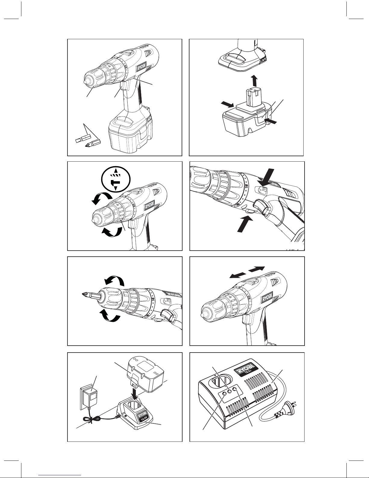
nPlace the battery pack in the charger aligning raised
rib on the battery pack with the groove in the charger.
See Figure 8.
nPress down on the battery pack to be sure contacts
on the battery pack engage properly with contacts in
the charger.
nNormally the red LED on charger will come on. This
indicates the charger is in fast charging mode.
nRed LED should remain on for approximately 1 hour
then the green LED will come on. Green LED on in-
dicates battery pack is fully charged and charger is in
maintenance charge mode.
NOTE: The green LED will remain on until the battery
pack is removed from the charger or charger is discon-
nected from the power supply.
nIf both yellow and green LEDs come on, this indicates
a deeply discharged or defective battery pack.Allow
the battery pack to remain in the charger for 15 to 30
minutes. When the battery pack reaches normalvoltage
range, the red LED should come on. If the red LED
does not come on after 30 minutes, this mayindicate
a defective battery pack and should bereplaced.
nAfter normal usage, a minimum of 1 hour of charging
time is required to fully recharge battery pack.
nThe battery pack will become slightly warm to touch
while charging. This is normal and does notindicate a
problem.
nDo not place the charger and battery pack in an area
of extreme heat or cold. They will work best at normal
room temperature.
NOTE: The charger and battery pack should be placed
in a location where the temperature is more than 10°C
but less than 38°C.
nWhen batteries become fully charged, unplug the-
charger from power supply and remove the battery
pack.
CHARGING A HOT BATTERY PACK
When using the tool continuously, the batteries in the bat-
tery pack will become hot. You should let a hot battery pack
cool down for approximately 30 minutes before attempting
to recharge. When the battery pack becomes discharged
and is hot, this will cause the green LED to come on in-
stead of the red LED. After 30 minutes, reinsert the battery
pack in the charger. If the green LED continues to remain
on, return battery pack to your nearest Ryobi Authorised
Service Centre for checking or replacing.
NOTE: This situation only occurs when continuous use of
the tool causes the batteries to become hot. It does not
occur under normal circumstances. Refer to “CHARGING
A COOL BATTERY PACK” for normal recharging of batter-
ies. If the charger does not charge your battery pack under
normal circumstances, return both the battery pack and
charger to your nearest Ryobi Authorised Service Centre
for electrical check.
TO INSTALL BATTERY PACK
nLock switch trigger on your drill by placing the direction
of rotation selector in center position. See Figure 4.
nPlace battery pack in your drill. Align raised rib on bat-
tery pack with groove inside drill. See Figure 2.
nMake sure the latches on battery pack snap in place
and battery pack is secured in drill before beginning
operation.
TO REMOVE BATTERY PACK
nLock switch trigger on your drill by placing the direction
of rotation selector in center position. See Figure 4.
nLocate latches of battery pack and depress to release
battery pack from your drill. See Figure 2.
nRemove battery pack from your drill.
960931156-01.indd A6960931156-01.indd A6 8/15/02 2:00:29 PM8/15/02 2:00:29 PM

7
OPERATION
ADJUSTING THE TORQUE
See Figure 3.
The tool is equipped with an adjustable torque clutch for
driving different types of screws into different materials.
Adjust the torque as necessary.
We recommend that you use carbide-tipped bits and select
impact mode when drilling in hard material such as brick,
tile, concrete, etc.
CAUTION
The impact drill is not designed for reverse ham-
mering. Failure to obey this caution may result in
property damage.
SWITCH
See Figure 4.
nTo turn your drill ON, depress the switch trigger.
nTo turn it OFF, release the switch trigger.
VARIABLE SPEED
This tool has a variable speed switch that delivers higher
speed and torque with increased trigger pressure. Speed is
controlled by the amount of switch trigger depression.
SWITCH LOCK
See Figure 4.
The switch trigger can be locked in the OFF position. This
feature can be used to prevent the possibility of accidental
starting when not in use. To lock switch trigger, place the
direction of rotation selector (Forward/Reverse Selector)
in center position.
NOTE: When selector is in center position, switch trigger
is locked.
REVERSIBLE
See Figure 4.
This tool has the feature of being reversible. The direction of
rotation is controlled by a selector located above the switch
trigger. With the drill held in normal operating position, the
direction of rotation selector should be positioned to the left
of the switch for drilling. The drilling direction is reversed
when the selector is to the right of the switch. When the
selector is in center position, the switch trigger is locked.
To stop, release switch trigger and allow the chuck to come
to a complete stop.
ELECTRIC BRAKE
This drill has an electric brake. When the trigger switch
is released, the chuck stops turning. When the brake is
functioning properly, sparks will be visible through the vent
slots on the housing. This is normal and is the action of
the brake.
KEYLESS CHUCK
See Figure 5.
Your drill has a keyless chuck. As the name implies, you can
hand tighten or release drill bits in the chuck jaws. Rotate
the chuck with your hand. Rotate the chuck body with your
other hand. The arrows on the chuck indicate which direc-
tion to rotate the chuck body in order to LOCK (tighten) or
UNLOCK (release) the drill bit.
WARNING
Do not hold chuck body with one hand and use
power of the drill to tighten chuck jaws on drill bit.
Chuck body could slip in your hand or your hand
could slip and come in contact with rotating drill bit.
This could cause an accident resulting in serious
personal injury.
ADJUSTING THE SPEED
See Figure 6.
Follow these steps to adjust the speed.
nFor high speed: Slide the two-speed gear train switch
to “2.”
nFor low speed: Slide the two-speed gear train switch
to “1.”
NOTE: If you have difficulty changing from one gear
range to the other, turn the chuck by hand until the
gears engage.
CAUTION
To prevent gear damage, always allow chuck to
come to a complete stop before changing the
speed or the direction of rotation.
MAINTENANCE
WARNING
When servicing, use only identical replacement
parts. Use of any other part may create a hazard
or cause product damage.
Avoid using solvents when cleaning plastic parts. Most
plastics are susceptible to damage from various types of
commercial solvents and may be damaged by their use. Use
clean cloths to remove dirt, dust, oil, grease, etc.
960931156-01.indd A7960931156-01.indd A7 8/15/02 2:00:29 PM8/15/02 2:00:29 PM

8
MAINTENANCE
WARNING
Do not at any time let brake fluids, gasoline, petro-
leum-based products, penetrating oils, etc. come in
contact with plastic parts. They contain chemicals
that can damage, weaken or destroy plastic.
Do not abuse power tools. Abusive practices can damage
tool as well as workpiece.
WARNING
Do not attempt to modify this tool or create acces-
sories not recommended for use with this tool. Any
such alteration or modification is misuse and could
result in a hazardous condition leading to possible
serious personal injury.
ENVIRONMENTAL PROTECTION
Recycle raw materials instead of disposing as
waste. The machine, accessories and packag-
ing should be sorted for en-vironmental-friendly
recycling.
960931156-01.indd A8960931156-01.indd A8 8/15/02 2:00:30 PM8/15/02 2:00:30 PM

4%#(42/.)#).$5342)%3!5342!,)!049,)-)4%$
'5!2!.4%%
!".
#ONTACT DURING NORMAL BUSINESS HOURS
!5#+,!.$ #LEMOW $RIVE -T 7ELLINGTON .:
#ONTACT DURING NORMAL BUSINESS HOURS
!,,!5342!,)!.%.15)2)%34%,
7%34!5342!,)!.%.15)2)%34%,
!
0URCHASED&ROM
DDRESS /F $EALER
0RESENT 4HIS &ORM 7ITH 9OUR 0URCHASE $OCKET 7HEN 'UARANTEE 3ERVICE )S 2EQUIRED
4EL &AX WWWRYOBICOMAU
4EL &REE #ALL &AX WWWRYOBICONZ
&OR YOUR RECORD AND TO ASSIST IN ESTABLISHING DATE OF PURCHASE NECESSARY FOR INGUARANTEE SERVICE
PLEASE KEEP YOUR PURCHASE DOCKET AND THIS FORM COMPLETED WITH THE FOLLOWING PARTICULARS
4HIS 'UARANTEE &ORM 3HOULD "E 2ETAINED "Y 4HE #USTOMER !T !LL 4IMES
$ATE -ODEL .O 3ERIAL .O
39$.%9"UILDING"2OSEHILL)NDUSTRIAL%STATE3HIRLEY3TREET2OSEHILL.37
4%#(42/.)#).$5342)%3!5342!,)!049,)-)4%$
4%#(42/.)#).$5342)%3.:,)-)4%$
3UBJECT TO THE GUARANTEE CONDITION BELOW THIS 2YOBI
TOOLHEREINAFTERCALLEDhTHEPRODUCTvISGUARANTEEDBY
4%#(42/.)# ).$5342)%3 !5342!,)! 049
,)-)4%$HEREINAFTERCALLEDhTHE#OMPANYvTOBEFREE
FROMDEFECTSINMATERIALORWORKMANSHIPFORAPERIODOF
MONTHSFROMTHEDATEOFORIGINALPURCHASECOVERING
BOTHPARTSANDLABOUR5NDERTHETERMSOFTHISGUARAN
TEETHEREPAIRORREPLACEMENTOFANYPARTSHALLBETHE
OPINION OF THE #OMPANY OR ITS AUTHORISED 3ERVICE
CENTRE3HOULDSERVICEBECOMENECESSARYDURINGTHE
WARRANTY PERIOD THE OWNER SHOULD CONTACT THE
CUSTOMERSERVICE(%,0,).%ORCONTACT
THERETAILERFROMWHOMTHEPRODUCTWASPURCHASED
)NORDERTOOBTAINGUARANTEESERVICETHEOWNERMUST
PRESENTTHESALESDOCKETAND'UARANTEE#ERTIFICATETO
CONFIRMDATEOFPURCHASE4HISPRODUCTISSOLDBYTHE
DEALER OR 3ERVICE CENTRE AS PRINCIPAL AND THE DEALER
HAS NO AUTHORITY FROM THE #OMPANY TO GIVE ANY
ADDITIONALGUARANTEEONTHE#OMPANYSBEHALFEXCEPT
ASHEREINCONTAINEDORHEREINREFERREDTO
'UARANTEE#ONDITIONS
4HISGUARANTEEONLYAPPLIESPROVIDEDTHATTHE0RODUCT
HASBEENUSEDINACCORDANCEWITHTHEMANUFACTURERS
RECOMMENDATIONSUNDER NORMALUSE ANDREASONABLE
CAREINTHEOPINIONOFTHE#OMPANYANDSUCH
GUARAN
TEE DOES NOT COVER DAMAGE MALFUNCTION OR FAILURE
RESULTING FROM MISUSE NEGLECT ABUSE OR USED FOR A
PURPOSEFORWHICHITWASNOTDESIGNEDORISNOTSUITED
ANDNOREPAIRSALTERATIONSORMODIFICATIONSHAVEBEEN
ATTEMPTEDBYOTHERTHANAN!UTHORISED3ERVICECENTRE
4HISGUARANTEEWILLNOTAPPLYIFTHETOOLISDAMAGEDBY
ACCIDENTORIFREPAIRSARISEFROMNORMALWEARANDTEAR
4HE#OMPANYACCEPTSNOADDITIONALLIABILITYPURSUANT
TOTHISGUARANTEEFORTHECOSTSOFTRAVELLINGORTRANSPOR
TATIONOFTHE0RODUCTORPARTSTOANDFROMTHESERVICE
DEALEROR3ERVICECENTRESUCHCOSTSARENOTINCLUDED
INTHISGUARANTEE
#ERTAINLEGISLATIONINCLUDINGTHE4RADE0RACTICES
!CT AS AMENDED AND OTHER STATE AND
TERRITORIALLAWSGIVERIGHTSTOTHEBUYERANDIMPOSE
LIABILITYONTHESELLERINCERTAINCIRCUMSTANCES.OTHING
HEREINSHALLHAVETHEEFFECTOFEXCLUDINGRESTRICTINGOR
MODIFYING ANY CONDITION GUARANTEE RIGHT OR LIABILITY
IMPOSED TO THE EXTENT ONLY THAT SUCH EXCLUSION
RESTRICTION OR MODIFICATION WOULD RENDER ANY TERM
HEREINVOID
960931156-01.indd A9960931156-01.indd A9 8/15/02 2:00:30 PM8/15/02 2:00:30 PM
Other manuals for CHI1442P
1
This manual suits for next models
1
Table of contents
Other Ryobi Drill manuals

Ryobi
Ryobi R18DD3-2415BS User manual

Ryobi
Ryobi ONE+ PSBDD01 User manual

Ryobi
Ryobi RCD18022L User manual

Ryobi
Ryobi Autoshift CDA1802 Operation manual

Ryobi
Ryobi 3000809 User manual

Ryobi
Ryobi ONE+ R18SDS-L25S User manual

Ryobi
Ryobi RAD1801 User manual

Ryobi
Ryobi RPD18X User manual

Ryobi
Ryobi RID18 User manual

Ryobi
Ryobi PBLCK02K User manual

Ryobi
Ryobi EID11002RV User manual

Ryobi
Ryobi RCD1201 User manual

Ryobi
Ryobi RCD1802 User manual

Ryobi
Ryobi PBLHM101 User manual

Ryobi
Ryobi R18PD3-0 User manual

Ryobi
Ryobi R18DD7-0 User manual

Ryobi
Ryobi R10511 User manual

Ryobi
Ryobi R18AD User manual

Ryobi
Ryobi LCDI1802 User manual

Ryobi
Ryobi R18SDS User manual