INSTRUCTIONS FOR SAFE HANDLING
English
SWITCH(FIG.1 &3)
.Make sure that the drill bit Is securely mounted. An
Incorrectly mounted bit Is extremely dangerous since
it can fly off or break during drilling.
. Dress properly. Do not wear loose clothing or
jewellery, they can be caught In moving parts.
Protective gloves and non-skid footwear are
recommended when working outdoors. Wear
protective hair covering to contain long hair.
.Hold the tool securely with both hands. If not held
securely, accidents or injury may result.
. Never touch the chuck or metal body parts when
drilling walls, floors, or other surfaces covering
electrical wiring. Hold the tool only by the plastic
handle to prevent electric shocks.
. While operating, the work piece must be securely
held with a vice or clamp etc. to prevent it from
moving due to the drill rotation.
SPECIFICATIONS
Voltage
Chuck capacity
Drilling capacity
inwood
insteel
in masonry
110V1230V-50Hz
13mm(1/2")
40mm
13mm
16mm
1050W
Input
No load speed
high
low
Blows per minute
high
low
Netweight
Safety class II
o.2,880min"
o - 1,300 min"
o - 46,080 min"
o - 20,800 min"
3.2kg
STANDARD ACCESSORIES
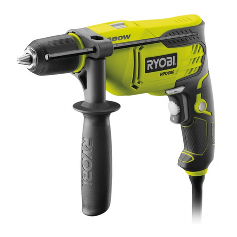
Auxiliary handle, Depth Stopper and Drill Bit.
APPLICATIONS. .
(Use only for the purposes listed below.)
.Drilling wood, materials and resin boards.
. Drilling concrete (impact drilling only).
.. Drilling metal, steel, brass, aluminum sheets,
stainless steel & pipe.
NOISE BUilD-UP
Noise (sound pressure level) In the workplace can
exceed 85 dB (A). In this case, sound insulation and
hearing protection measures must be taken by the
operator.
.This tool Is started and stopped by pressing and
releasing the trigger switch (A).
.The speed can be adjusted in either gear by
controlling the force applied to the trigger.
. The maximum speed of the drill may be set at
different speeds by adjusting the variable speed
selector (D).
.For continuous operation, press the lock button (E)
while squeezing the trigger. Squeeze the trigger again
to release the lock.
CHANGING THE ROTATION DIRECTlON(FIG. 2)
.To change the direction 01 rotation, stop the tool and
push the forward 1reverse button (B).
.When the forward button Is pushed In, the bit rotates
clockwise when vlawed from the handle end of the
tool.
.When the reverse button Is pushed In, the bit rotates
counterclockwise.
SPINDLE LOCK ,
For lIasy changing of the drill bit, this drill is equipped
with an automatic spindle lock which holds the spindle
stationary when loosening and tightening the chuck.
WARNINGI
AAlways be sure the spindle lock button Is
released and the spindle lock is disengaged
before turning the drill ON.
MOUNTING AND REMOVING THE BIT(FIG. 4)
.Insert the drill bit (J) Into the chuck as far as the plain
part of its shank will go.
.Tighten the chuck securely by rotating the chuck
head clockwise.
.The bit can be removed by rotating the chuck
counter-clockwise.
CHANGING BETWEEN DRilLING AND IMPACT
DRilLING MODE (FIG. 5)
The drilling mode shift knob (F) for changing between
the drilling mode and impact drilling mode is positioned
on the top of the tool.
DRILLING MODE: Shift the knob to the" ..,. "
symbol for rotation without Impact action.
IMPACT DRILLING MODE: Shift the knob to the" ... "
symbol for Impact drilling.
2
English
OPERATION
NEVER COVER THE AIR VENTS (K) SINCE THEY
MUST ALWAYS BE OPEN FOR PROPER MOTOR
COOLING.
DRilLING IN WOOD
To prevent ugly splits around the drill hole on the reverse
side of the workpiece, put a piece of scrap timber under
the work piece.
DRilLING IN METAL
Metals such as steel, brass,aluminum sheets, stainless
steel, and pipe may also be drilled. Mark the point to be
drilled with a nail or punch.
Do not use impact mode on these materials.
DRilLING IN CONCRETE
Stone and masonry are generally drilled in the Impact
.drilling mode.
When drilling in delicate materials such as wall tiles, it is
essential to start with ordinary drilling and, once the tile
is pierced, to continue with impact drilling.
In deep bore holes the drill bit should be pulled out
occasionally in order to remove the debris from the drill
and hole.
AUXILIARY HANDLEAND STOPPERPOLE
(FIG. 6)
Auxiliary handle
The auxiliary handle (I) can be rotated 360.
loosen the handle grip by turning in direction L,
and tighten it at an easy to-use position by turning
the grip in direction M.
BIT STORAGE (FIG. 7)
The auxiliary handle also contains a compartment to
store drill bits. To access this compartment unscrew the
end cap below the Yellow trim on the handle In an
anticlockwise direction.
DEPTH STOPPER .
Holes of a fixed depth can be accurately bored by using
the depth stopper (G).
The depth of the hole will be the distance from the end
of the bit to the end of the stopper pole.
By turning the handle grip in direction L, the stopper pole
can be released and the depth adjusted. After adjusting
the depth, fix the stopper pole again by turning
the handle grip in direction M.
CHANGING THE ROTATION SPEED (FIG. 8)
The rotation speed can only be changed when the tool
is at a standstill.
The gear setting knob (H) is on the left side of the
housing.
When the knob is in position "1" the tool is in the low
gear.
When the knob is in position "2" the tool is in the high
gear.
LIVE TOOL INDICATOR
This tool features a live tool indicator (L) which
illuminates as soon as the tool is connected to the
supply. This warns the user that the tool is connected and
will operate when the switch is pressed.
MAINTENANCE
After use, check the tool to make sure that it is in good
condition. It is recommended that you take this tool to
a RYOBI Authorized Service Center for a thorough
cleaning and lubrication at least once a year.
DO NOT MAKE ANY ADJUSTMENTS WHILE THE
MOTOR IS IN MOTION.
ALWAYS DISCONNECT THE POWER CORD FROM
THE POWER SUPPLY BEFORE CHANGING
REMOVABLE OR CONSUMABLE PARTS (BLADE,
BIT), BEFORE LUBRICATING OR WORKING ON
THE UNIT.
WARNING'
ATo ensure safety and reliability, all repairs should
be performed by an AUTHORIZED SERVICE
CENTER or other QUALIFIED SERVICE
ORGANIZATION.
SAVE THESE INSTRUCTIONS FOR FUTURE
REFERENCE.
3
