Ryobi P205 User manual

SAVE THIS MANUAL FOR FUTURE REFERENCE
Your drill-driver has been engineered and manufactured to our high standard for dependability, ease of operation, and
operator safety. When properly cared for, it will give you years of rugged, trouble-free performance.
WARNING: To reduce the risk of injury, the user must read and understand the operator’s manual before using
this product.
Thank you for your purchase.
OPERATOR’S MANUAL
MANUEL D’UTILISATION
MANUAL DEL OPERADOR
18 VOLT, 3/8 in. DRILL-DRIVER
PERCEUSE-TOURNEVIS 10 mm (3/8 po) 18 V
TALADRO-DESTORNILLADOR
10 mm (3/8 pulg.) 18 V
P205
Cette perceuse-tournevis a été conçue et fabriquée conformément
à nos strictes normes de fiabilité, simplicité d’emploi et sécurité
d’utilisation.Correctemententretenue,ellevousdonneradesannées
de fonctionnement robuste et sans problème.
AVERTISSEMENT : Pour réduire les risques de
blessures, l’utilisateur doit lire et veiller à bien comprendre le
manuel d’utilisation avant d’employer ce produit.
Merci de votre achat.
Su taladro-destornillador ha sido diseñada y fabricada de
conformidad con las estrictas normas para brindar fiabilidad,
facilidaddeusoy seguridadparaeloperador. Coneldebidocuidado,
le brindará muchos años de sólido y eficiente funcionamiento.
ADVERTENCIA: Para reducir el riesgo de lesiones,
el usuario debe leer y comprender el manual del operador antes
de usar este producto.
Le agradecemos su compra.
CONSERVER CE MANUEL POUR
FUTURE RÉFÉRENCE
GUARDE ESTE MANUAL PARA
FUTURAS CONSULTAS

− English
Introduction ..................................................................................................................................................................... 2
Warranty .......................................................................................................................................................................... 2
General Safety Rules....................................................................................................................................................3-4
Specific Safety Rules....................................................................................................................................................... 4
Symbols........................................................................................................................................................................5-6
Features........................................................................................................................................................................... 7
Assembly......................................................................................................................................................................... 8
Operation....................................................................................................................................................................8-11
Maintenance.............................................................................................................................................................12-13
Parts Ordering / Service ................................................................................................................................... Back page
TABLE OF CONTENTS
INTRODUCTION
This tool has many features for making its use more pleasant and enjoyable. Safety, performance, and dependability have
been given top priority in the design of this product making it easy to maintain and operate.
WARRANTY
RYOBI®POWER TOOL - LIMITED TWO YEAR WARRANTY AND 30 DAY EXCHANGE POLICY
One World Technologies, Inc., warrants its RYOBI®power tools with the following conditions:
30-DAY EXCHANGE POLICY: During the first 30 days after date of purchase, you may either request service under this
warranty or you may exchange any RYOBI®power tool which does not work properly due to defective workmanship or
materials by returning the power tool to the dealer from which it was purchased. To receive a replacement power tool or re-
quested warranty service, you must present proof of purchase and return all original equipment packaged with the original
product. The replacement power tool will be covered by the limited warranty for the balance of the two year period from
the date of the original purchase.
WHAT THIS WARRANTY COVERS: This warranty covers all defects in workmanship or materials in your RYOBI®power
tool for a period of two years from the date of purchase. With the exception of batteries, power tool accessories are war-
ranted for ninety (90) days. Batteries are warranted for two years.
HOW TO GET SERVICE: Just return the power tool, properly packaged and postage prepaid, to an Authorized Ser-
vice Center. You can obtain the location of the Service Center nearest you by contacting a service representative at
One World Technologies, Inc., P.O. Box 1207, Anderson, SC 29622-1207, by calling 1-800-525-2579 or by logging on to
www.ryobitools.com. When you request warranty service, you must also present proof of purchase documentation, which
includes the date of purchase (for example, a bill of sale). We will repair any faulty workmanship, and either repair or replace
any defective part, at our option. We will do so without any charge to you. We will complete the work in a reasonable time,
but, in any case, within ninety (90) days or less.
WHAT’S NOT COVERED: This warranty applies only to the original purchaser at retail and may not be transferred. This
warranty only covers defects arising under normal usage and does not cover any malfunction, failure or defects resulting
from misuse, abuse, neglect, alteration, modification or repairs by other than Authorized Service Centers. One World Tech-
nologies, Inc. makes no warranties, representations or promises as to the quality or performance of its power tools other
than those specifically stated in this warranty.
ADDITIONAL LIMITATIONS: Any implied warranties granted under state law, including warranties of merchantability or
fitness for a particular purpose, are limited to two years from the date of purchase. One World Technologies, Inc. is not
responsible for direct, indirect, or incidental damages, so the above limitations and exclusions may not apply to you. This
warranty gives you specific legal rights, and you may also have other rights which vary from state to state.

− English
GENERAL SAFETY RULES
WARNING!
READ AND UNDERSTAND ALL INSTRUCTIONS. Fail-
ure to follow all instructions listed below, may result in
electric shock, fire and/or serious personal injury.
SAVE THESE INSTRUCTIONS
WORK AREA
Keep your work area clean and well lit. Cluttered
benches and dark areas invite accidents.
Do not operate power tools in explosive atmo-
spheres, such as in the presence of flammable
liquids, gases, or dust. Power tools create sparks which
may ignite the dust or fumes.
Keep bystanders, children, and visitors away while
operating a power tool. Distractions can cause you to
lose control.
ELECTRICAL SAFETY
A battery operated tool with integral batteries or a
separate battery pack must be recharged only with
the specified charger for the battery. A charger that
may be suitable for one type of battery may create a risk
of fire when used with another battery.
Use battery operated tool only with specifically
designated battery pack. Use of any other batteries
may create a risk of fire.
Use battery only with charger listed.
Avoid accidental starting. Be sure switch is in the
locked or off position before inserting battery pack.
Carrying tools with your finger on the switch or inserting
the battery pack into a tool with the switch on invites
accidents.
Remove adjusting keys or wrenches before turning
the tool on. A wrench or a key that is left attached to a
rotating part of the tool may result in personal injury.
Do not overreach. Keep proper footing and balance
at all times. Proper footing and balance enable better
control of the tool in unexpected situations.
Use safety equipment. Always wear eye protection.
Dust mask, non-skid safety shoes, hard hat, or hearing
protection must be used for appropriate conditions.
Do not wear loose clothing or jewelry. Contain long
hair. Loose clothes, jewelry, or long hair can be drawn
into air vents.
Do not use on a ladder or unstable support. Stable
footing on a solid surface enables better control of the
tool in unexpected situations.
TOOL USE AND CARE
Use clamps or other practical way to secure and sup-
port the workpiece to a stable platform. Holding the
work by hand or against your body is unstable and may
lead to loss of control.
Do not force tool. Use the correct tool for your
application. The correct tool will do the job better and
safer at the rate for which it is designed.
Do not use tool if switch does not turn it on or off.
A tool that cannot be controlled with the switch is
dangerous and must be repaired.
Disconnect battery pack from tool or place the switch
in the locked or off position before making any adjust-
ments, changing accessories, or storing the tool. Such
preventive safety measures reduce the risk of starting the
tool accidentally.
Store idle tools out of reach of children and other
untrained persons. Tools are dangerous in the hands
of untrained users.
When battery pack is not in use, keep it away from
other metal objects like: paper clips, coins, keys, nails,
screws, or other small metal objects that can make
a connection from one terminal to another. Shorting
the battery terminals together may cause sparks, burns,
or a fire.
Maintain tools with care. Keep cutting tools sharp
and clean. Properly maintained tools with sharp
cutting edges are less likely to bind and are easier to
control.
Check for misalignment or binding of moving parts,
breakage of parts, and any other condition that may
affect the tool’s operation. If damaged, have the tool
serviced before using. Many accidents are caused by
poorly maintained tools.
PERSONAL SAFETY
Stay alert, watch what you are doing and use
common sense when operating a power tool. Do not
use tool while tired or under the influence of drugs,
alcohol, or medication. A moment of inattention while
operating power tools may result in serious personal
injury.
Dress properly. Do not wear loose clothing or jewelry.
Contain long hair. Keep your hair, clothing, and gloves
away from moving parts. Loose clothes, jewelry, or long
hair can be caught in moving parts.
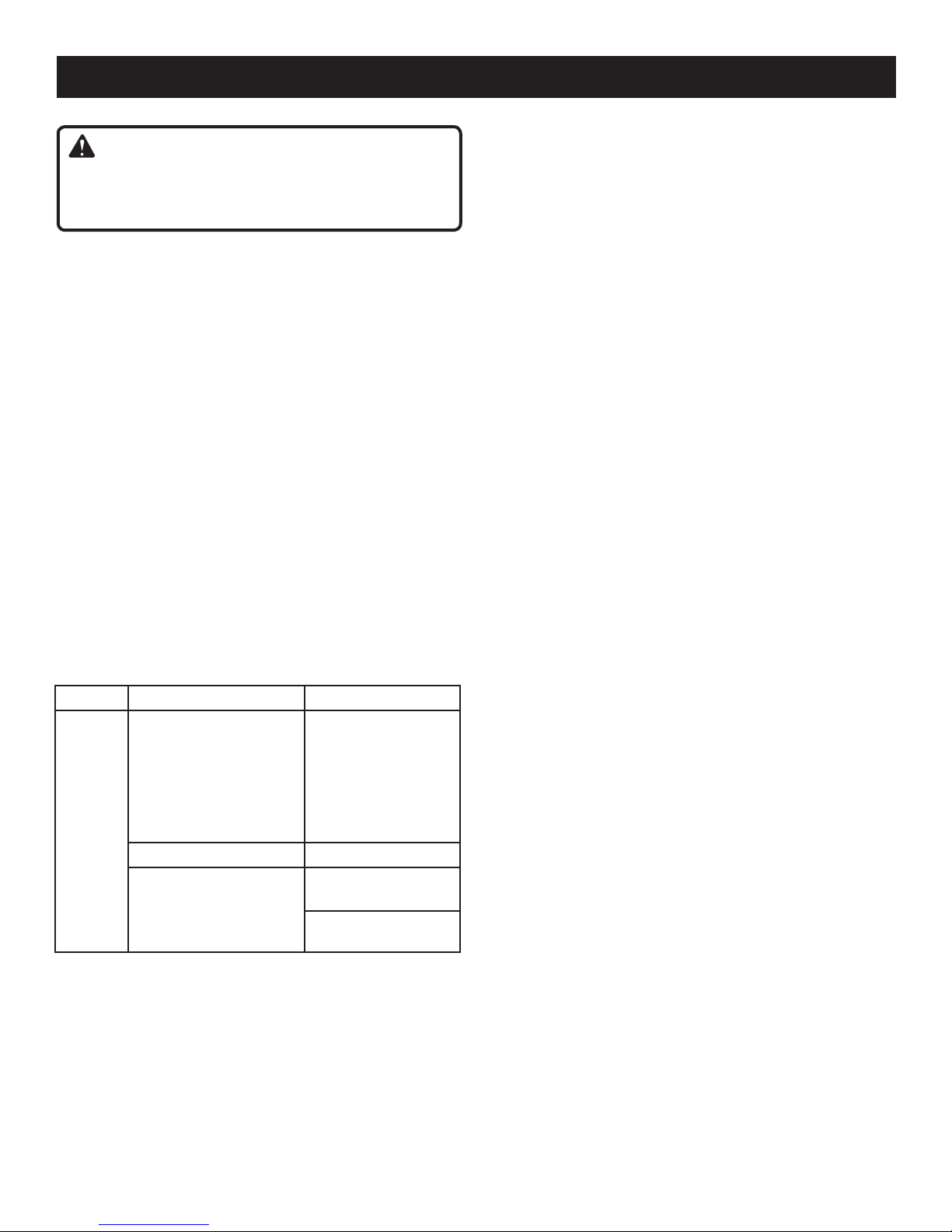
MODEL BATTERY PACK CHARGER (P113)
P205
(P104 Li-ion)
130429001, 130429002
130155001
(P103 Li-ion):
130429004
(P100 Ni-Cd)
130255004, 130224028
140501001
140501005
BATTERY PACK CHARGER (P110)
(P100 Ni-Cd)
130255004, 130224028
1423701, 140237021,
140237023
CHARGER (P111)
140106001

− English
Hold tool by insulated gripping surfaces when
performing an operation where the cutting tool may
contact hidden wiring. Contact with a “live” wire will also
make exposed metal parts of the tool “live” and shock
the operator.
Know your power tool. Read operator’s manual
carefully. Learn its applications and limitations, as well
as the specific potential hazards related to this tool.
Following this rule will reduce the risk of electric shock,
fire, or serious injury.
Always wear safety glasses with side shields. Everyday
glasses have only impact resistant lenses. They are NOT
safety glasses. Following this rule will reduce the risk of
eye injury.
Protect your lungs. Wear a face or dust mask if the
operation is dusty. Following this rule will reduce the
risk of serious personal injury.
Protect your hearing. Wear hearing protection during
extended periods of operation. Following this rule will
reduce the risk of serious personal injury.
Battery tools do not have to be plugged into an
electrical outlet; therefore, they are always in
operating condition. Be aware of possible hazards
when not using your battery tool or when changing
accessories. Following this rule will reduce the risk of
electric shock, fire, or serious personal injury.
Do not place battery tools or their batteries near fire or
heat. Following this rule will reduce the risk of explosion
and possibly injury.
Use only accessories that are recommended by the
manufacturer for your model. Accessories that may be
suitable for one tool may create a risk of injury when used
on another tool.
Keep the tool and its handle dry, clean and free from
oil and grease. Always use a clean cloth when cleaning.
Never use brake fluids, gasoline, petroleum-based
products, or any strong solvents to clean your tool.
Following this rule will reduce the risk of loss of control
and deterioration of the enclosure plastic.
Never use a battery that has been dropped or received
a sharp blow. A damaged battery is subject to explosion.
Properly dispose of a dropped or damaged battery
immediately.
Batteries can explode in the presence of a source
of ignition, such as a pilot light. To reduce the risk of
serious personal injury, never use any cordless product
in the presence of open flame. An exploded battery can
propel debris and chemicals. If exposed, flush with water
immediately.
Do not charge battery tool in a damp or wet location.
Following this rule will reduce the risk of electric shock.
For best results, your battery tool should be charged
in a location where the temperature is more than
50°F but less than 100°F. Do not store outside or in
vehicles.
Under extreme usage or temperature conditions,
battery leakage may occur. If liquid comes in contact
with your skin, wash immediately with soap and water,
then neutralize with lemon juice or vinegar. If liquid
gets into your eyes, flush them with clean water for
at least 10 minutes, then seek immediate medical
attention. Following this rule will reduce the risk of serious
personal injury.
Save these instructions. Refer to them frequently
and use them to instruct others who may use this
tool. If you loan someone this tool, loan them these
instructions also to prevent misuse of the product and
possible injury.
SERVICE
Tool service must be performed only by qualified
repair personnel. Service or maintenance performed by
unqualified personnel may result in a risk of injury.
When servicing a tool, use only identical replacement
parts. Follow instructions in the Maintenance section
of this manual. Use of unauthorized parts or failure to
follow Maintenance Instructions may create a risk of
shock or injury.
GENERAL SAFETY RULES
SPECIFIC SAFETY RULES

− English
SYMBOLS
Some of the following symbols may be used on this product. Please study them and learn their meaning. Proper
interpretation of these symbols will allow you to operate the product better and safer.
SYMBOL NAME DESIGNATION/EXPLANATION
V Volts Voltage
A Amperes Current
Hz Hertz Frequency (cycles per second)
W Watt Power
min Minutes Time
Alternating Current Type of current
Direct Current Type or a characteristic of current
n
o
No Load Speed Rotational speed, at no load
Class II Construction Double-insulated construction
.../min Per Minute Revolutions, strokes, surface speed, orbits etc., per minute
Wet Conditions Alert Do not expose to rain or use in damp locations.
Read The Operator’s Manual To reduce the risk of injury, user must read and understand
operator’s manual before using this product.
Eye Protection Always wear safety goggles or safety glasses with side shields and,
as necessary, a full face shield when operating this product.
Safety Alert Precautions that involve your safety.
Hot Surface To reduce the risk of injury or damage, avoid contact with any hot
surface.
The following signal words and meanings are intended to explain the levels of risk associated with this product.
SYMBOL SIGNAL MEANING
DANGER: Indicates an imminently hazardous situation, which, if not avoided, will result
in death or serious injury.
WARNING: Indicates a potentially hazardous situation, which, if not avoided, could result
in death or serious injury.
CAUTION: Indicates a potentially hazardous situation, which, if not avoided, may result in
minor or moderate injury.
CAUTION: (Without Safety Alert Symbol) Indicates a situation that may result in property
damage.

− English
SYMBOLS
SERVICE
Servicing requires extreme care and knowledge and should
be performed only by a qualified service technician. For
service we suggest you return the product to the nearest
AUTHORIZED SERVICE CENTER for repair. When
servicing, use only identical replacement parts.
WARNING:
To avoid serious personal injury, do not attempt
to use this product until you read thoroughly and
understand completely the operator’s manual. If you
do not understand the warnings and instructions in the
operator’s manual, do not use this product. Call Ryobi
customer service for assistance.
WARNING:
The operation of any power tool can result in foreign objects being thrown into your eyes, which can
result in severe eye damage. Before beginning power tool operation, always wear safety goggles or
safety glasses with side shields and, when needed, a full face shield. We recommend Wide Vision
Safety Mask for use over eyeglasses or standard safety glasses with side shields. Always use eye
protection which is marked to comply with ANSI Z87.1.
WARNING:
Some dust created by power sanding, sawing, grinding, drilling, and other construction activities contains
chemicals known to cause cancer, birth defects or other reproductive harm. Some examples of these
chemicals are:
•lead from lead-based paints,
•crystalline silica from bricks and cement and other masonry products, and
•arsenic and chromium from chemically-treated lumber.
Your risk from these exposures varies, depending on how often you do this type of work. To reduce your
exposure to these chemicals: work in a well ventilated area, and work with approved safety equipment, such
as those dust masks that are specially designed to filter out microscopic particles.
SAVE THESE INSTRUCTIONS

− English
FEATURES
Fig. 1
Keyless
ChuCK
Torque
AdjusTmenT ring
swiTCh
Trigger
Two-sPeed
geAr TrAin (hi-lo)
mAg TrAy™
(sCrew holder/BiT
sTorAge)
direCTion oF
roTATion seleCTor
(ForwArd/reVerse
/CenTer loCK)
PRODUCT SPECIFICATIONS
Chuck .......................................................... 3/8 in. Keyless
Motor..................................................................... 18 V DC
Switch..........................................................Variable Speed
No Load Speed .......................0-350/0-1,300 r/min. (RPM)
Clutch.................................................................24 position
Torque...................................................................330 in.lb.
KNOW YOUR DRILL-DRIVER
See Figure 1.
The safe use of this product requires an understanding of
the information on the tool and in this operator’s manual as
well as a knowledge of the project you are attempting. Before
use of this product, familiarize yourself with all operating
features and safety rules.
DIRECTION OF ROTATION SELECTOR
(FORWARD/REVERSE/CENTER LOCK)
Your drill has a direction of rotation (forward/reverse/center
lock) selector located above the switch trigger for changing
the direction of bit rotation. Setting the direction of rotation
selector in the OFF (center lock) position helps reduce the
possibility of accidental starting when not in use.
KEYLESS CHUCK
The keyless chuck allows you to hand-tighten or release the
drill bit in the chuck jaws.
MAG TRAY™
The magnetic tray conveniently stores bits and screws or
other small parts.
TORQUE ADJUSTMENT RING
Your drill has a 24-position clutch. The torque adjustment
ring can be turned to select the right amount of torque for
your application.
TWO-SPEED GEAR TRAIN
The two-speed gear train is designed for drilling or driving
at LO (1) or HI (2) speeds. A slide switch is located on top
of your drill for selecting either LO (1) or HI (2) speed.
VARIABLE SPEED
The switch trigger delivers higher speed with increased
trigger pressure and lower speed with decreased trigger
pressure.
leVel

− English
WARNING:
If any parts are damaged or missing do not operate this
tool until the damaged or missing parts are replaced.
Failure to do so could result in possible serious personal
injury.
WARNING:
Do not attempt to modify this tool or create accesso-
ries not recommended for use with this tool. Any such
alteration or modification is misuse and could result in a
hazardous condition leading to possible serious personal
injury.
WARNING:
To prevent accidental starting that could cause serious
personal injury, always remove the battery pack from the
tool when assembling parts.
ASSEMBLY
UNPACKING
This product has been shipped completely assembled.
Carefully remove the tool and any accessories from the
box. Make sure that all items listed in the packing list are
included.
Inspect the tool carefully to make sure no breakage or
damage occurred during shipping.
Do not discard the packing material until you have care-
fully inspected and satisfactorily operated the tool.
If any parts are damaged or missing, please call
1-800-525-2579 for assistance.
PACKING LIST
Drill-Driver
Double-ended Bit
Operator’s Manual
OPERATION
WARNING:
Do not allow familiarity with tools to make you care-
less. Remember that a careless fraction of a second is
sufficient to inflict serious injury.
WARNING:
Always wear safety goggles or safety glasses with side
shields when operating tools. Failure to do so could re-
sult in objects being thrown into your eyes, resulting in
possible serious injury.
WARNING:
Do not use any attachments or accessories not recom-
mended by the manufacturer of this tool. The use of at-
tachments or accessories not recommended can result
in serious personal injury.
APPLICATIONS
You may use this tool for the purposes listed below:
Drilling in all types of wood products (lumber, plywood,
paneling, composition board, and hardwood)
Drilling in ceramics, plastics, fiberglass, and laminates
Drilling in metals
Mixing paint
This product will accept Ryobi One+ 18 V lithium-ion bat-
tery packs and Ryobi One+ 18 V nickel-cadmium battery
packs.
For complete charging instructions, refer to the Operator’s
Manual for the battery packs and chargers listed in the
General Safety Rules.
TO INSTALL BATTERY PACK
See Figure 2.
Place the direction of rotation selector in center
position.
Align raised rib on battery pack with groove in drill’s bat-
tery port.
Make sure the latches on each side of the battery pack
snap in place and that battery pack is secure before
beginning operation.
TO REMOVE BATTERY PACK
Place the direction of rotation selector in center
position.
Locate latches on side of battery pack and depress both
sides to release battery pack from the drill.
Remove battery pack from the drill.

− English
Fig. 2
BATTery PACK lATChes
dePress lATChes
To releAse BATTery PACK
OPERATION
WARNING:
Battery tools are always in operating condition. There-
fore, switch should always be locked when not in use or
carrying at your side.
SWITCH TRIGGER
See Figure 3.
To turn the drill ON, depress the switch trigger. To turn it
OFF, release the switch trigger.
VARIABLE SPEED
The switch trigger delivers higher speed and torque with
increased trigger pressure and lower speed with decreased
trigger pressure.
NOTE: You might hear a whistling or ringing noise from the
switch during use. Do not be concerned; this is a normal
part of the switch function.
DIRECTION OF ROTATION SELECTOR
(FORWARD/REVERSE/CENTER LOCK)
See Figure 3.
The direction of bit rotation is reversible and is controlled
by a selector located above the switch trigger. With the drill
held in normal operating position, the direction of rotation
selector should be positioned to the left of the switch trigger
for drilling. The drilling direction is reversed when the selector
is to the right of the switch trigger.
Setting the direction of rotation selector in the OFF (center
lock) position helps reduce the possibility of accidental start-
ing when not in use.
CAUTION:
To prevent gear damage, always allow the chuck to
come to a complete stop before changing the direction
of rotation.
To stop the drill, release the switch trigger and allow the
chuck to come to a complete stop.
NOTE: The drill will not run unless the direction of rotation
selector is pushed fully to the left or right.
Avoid running the drill at low speeds for extended periods
of time. Running at low speeds under constant usage may
cause the drill to become overheated. If this occurs, cool the
drill by running it without a load and at full speed.
KEYLESS CHUCK
See Figure 3.
The drill has a keyless chuck to tighten or release drill bits
in the chuck jaws. Grasp and hold the collar of the chuck
with one hand. Rotate the chuck body with your other
hand. The arrows on the chuck indicate which direction
to rotate the chuck body in order to LOCK (tighten) or
UNLOCK (release) the drill bit.
WARNING:
Do not hold the chuck body with one hand and use the
power of the drill to tighten the chuck jaws on the drill
bit. The chuck body could slip in your hand, or your
hand could slip and come in contact with the rotating
drill bit. This could cause an accident resulting in serious
personal injury.
Fig. 3
reVerse
unloCK
(releAse)
loCK
(TighTen)
ChuCK
Body
ChuCK
CollAr
direCTion oF roTATion seleCTor
(ForwArd/reVerse/CenTer loCK)
ForwArd
swiTCh
Trigger

10 − English
OPERATION
TWO-SPEED GEAR TRAIN
See Figure 4.
The drill has a two-speed gear train designed for drilling or
driving at LO (1) or HI (2) speeds. A slide switch is located on
top of the drill to select either LO (1) or HI (2) speed. When
using drill in the LO (1) speed range, speed will decrease
and unit will have more power and torque. When using drill
in the HI (2) speed range, speed will increase and unit will
have less power and torque. Use LO (1) speed for high power
and torque applications and HI (2) speed for fast drilling or
driving applications.
ADJUSTABLE TORQUE CLUTCH
This product is equipped with an adjustable torque clutch
for driving different types of screws into different materials.
The proper setting depends on the type of material and the
size of screw you are using.
ADJUSTING TORQUE
See Figure 5.
There are twenty-four torque indicator settings located on
the front of the drill.
Rotate adjustment ring to the desired setting.
• 1 - 4 For driving small screws
• 5 - 8 For driving screws into soft material
• 9 - 12 For driving screws into soft and hard
materials
• 13 - 16 For driving screws in hard wood
• 17 - 20 For driving large screws
• 21 - For heavy drilling
INSTALLING BITS
See Figure 6-7.
Lock the switch trigger by placing the direction of rotation
selector in the center position.
Open or close the chuck jaws to a point where the open-
ing is slightly larger than the bit size you intend to use.
Also, raise the front of the drill slightly to keep the bit from
falling out of the chuck jaws.
Insert the drill bit.
Tighten the chuck jaws on the drill bit. To tighten, grasp
and hold the collar of the chuck with one hand, while
rotating the chuck body with your other hand.
NOTE: Rotate the chuck body in the direction of the ar-
row marked LOCK to tighten the chuck jaws.
WARNING:
Make sure to insert the drill bit straight into the chuck
jaws. Do not insert the drill bit into the chuck jaws at an
angle then tighten, as shown in figure 7. This could cause
the drill bit to be thrown from the drill, resulting in possible
serious personal injury or damage to the chuck.
NOTE: Do not use a wrench to tighten or loosen the chuck
jaws.
lo
sPeed
hi
sPeed
Two-sPeed
geAr TrAin (hi-lo)
Fig. 4
Fig. 5
To deCreAse
Torque
To inCreAse
Torque
Torque
AdjusTmenT ring
ChuCK
jAws
unloCK
(releAse)
loCK
(TighTen)
ChuCK
Body
BiT
Fig. 6
righT
2
1
ChuCK CollAr
REMOVING BITS
See Figure 6.
Place the direction of rotation selector in center position.
This will lock the switch trigger in the off position.

11 − English
OPERATION
wrong
Loosen the chuck jaws from drill bit.
To loosen the chuck jaws from the drill bit, grasp and
hold the collar of the chuck with one hand, while rotating
chuck body with your other hand.
NOTE: Rotate chuck body in the direction of the arrow
marked UNLOCK to loosen chuck jaws.
Remove drill bit from chuck jaws.
DRILLING
See Figure 8.
A level is located on top of the motor housing to help keep
the drill bit level during use.
Check the direction of rotation selector for the correct
setting (forward or reverse).
Secure the material to be drilled in a vise or with clamps
to keep it from turning as the drill bit rotates.
Hold the drill firmly and place the bit at the point to be
drilled.
Depress the switch trigger to start the drill.
Move the drill bit into the workpiece, applying only enough
pressure to keep the bit cutting. Do not force the drill or
apply side pressure to elongate a hole. Let the tool do
the work.
WARNING:
Be prepared for binding at bit breakthrough. When these
situations occur, the drill has a tendency to grab and kick
in the opposite direction and could cause loss of control
when breaking through material. If not prepared, this loss
of control can result in possible serious injury.
When drilling hard, smooth surfaces, use a center punch
to mark the desired hole location. This will prevent the
drill bit from slipping off-center as the hole is started.
When drilling metals, use a light oil on the drill bit to keep
it from overheating. The oil will prolong the life of the bit
and increase the drilling action.
If the bit jams in the workpiece or if the drill stalls, stop
the tool immediately. Remove the bit from the workpiece
and determine the reason for jamming.
NOTE: This drill has an electric brake. When the switch
trigger is released, the chuck stops turning. When the brake
is functioning properly, sparks will be visible through the
vent slots on the housing. This is normal and is the action
of the brake.
WOOD DRILLING
For maximum performance, use high speed steel bits for
wood drilling.
Begin drilling at a very low speed to prevent the bit from
slipping off the starting point. Increase the speed as the
drill bit bites into the material.
When drilling through holes, place a block of wood behind
the workpiece to prevent ragged or splintered edges on
the back side of the hole.
Fig. 8
Fig. 7
METAL DRILLING
For maximum performance, use high speed steel bits for
metal or steel drilling.
Begin drilling at a very low speed to prevent the bit from
slipping off the starting point.
Maintain a speed and pressure which allows cutting
without overheating the bit. Applying too much pressure
will:
• Overheat the drill;
• Wear the bearings;
• Bend or burn bits; and
• Produce off-center or irregular-shaped holes.
When drilling large holes in metal, start with a small bit,
then finish with a larger bit. Also, lubricate the bit with oil
to improve drilling action and increase bit life.

1 − English
MAINTENANCE
BATTERY PACK REMOVAL AND PREPARATION
FOR RECYCLING
To preserve natural resources, please
recycle or dispose of batteries
properly.
This product uses nickel-cadmium and
lithium-ion batteries. Local, state or
federal laws may prohibit disposal of
batteries in ordinary trash.
Consult your local waste authority for
informationregardingavailablerecycling
and/or disposal options.
WARNING:
Upon removal, cover the battery pack’s terminals with
heavy-duty adhesive tape. Do not attempt to destroy or
disassemble battery pack or remove any of its compo-
nents. Lithium-ion and nickel-cadmium batteries must
be recycled or disposed of properly. Also, never touch
both terminals with metal objects and/or body parts as
short circuit may result. Keep away from children. Failure
to comply with these warnings could result in fire and/or
serious injury.
Li - Ion
BATTERIES
This product will accept Ryobi One+ 18 V lithium-ion battery
packs and Ryobi One+ 18 V nickel-cadmium battery packs.
Length of service from each charging will depend on the type
of work you are doing.
The batteries for this product have been designed to provide
maximum trouble-free life. However, like all batteries, they
will eventually wear out. Do not disassemble battery pack
and attempt to replace the batteries. Handling of these
batteries, especially when wearing rings and jewelry, could
result in a serious burn.
To obtain the longest possible battery life, we suggest the
following:
For lithium-ion batteries:
Remove the battery pack from the charger once it is fully
charged and ready for use.
For battery pack storage longer than 30 days:
Store the battery pack where the temperature is below
80°F and away from moisture.
Store battery packs in a 30%-50% charged condition.
Every six months of storage, charge the pack as
normal.
For nickel-cadmium batteries:
Remove the battery pack from the charger once it is fully
charged and ready for use.
For battery pack storage longer than 30 days:
Store the battery pack where the temperature is below
80°F.
Store battery packs in a “discharged” condition.
WARNING:
When servicing, use only identical replacement parts.
Use of any other parts may create a hazard or cause
product damage.
WARNING:
Always wear safety goggles or safety glasses with side
shields during power product operation or when blowing
dust. If operation is dusty, also wear a dust mask.
WARNING:
To avoid serious personal injury, always remove the
battery pack from the product when cleaning or
performing any maintenance.
GENERAL MAINTENANCE
Avoid using solvents when cleaning plastic parts. Most
plastics are susceptible to damage from various types of
commercial solvents and may be damaged by their use. Use
clean cloths to remove dirt, dust, oil, grease, etc.
WARNING:
Do not at any time let brake fluids, gasoline, petroleum-
based products, penetrating oils, etc., come in contact
with plastic parts. Chemicals can damage, weaken or
destroy plastic which may result in serious personal
injury.
Only the parts shown on the parts list are intended to be
repaired or replaced by the customer. All other parts should
be replaced at an Authorized Service Center.

1 − English
Fig. 11
MAINTENANCE
CHUCK REMOVAL
See Figures 9 - 11.
The chuck may be removed and replaced by a new one.
Lock the switch trigger by placing the direction of rotation
selector in center position.
Insert a 5/16 in. or larger hex key into the chuck of the
drill and tighten the chuck jaws securely.
Tap the hex key sharply with a mallet in a clockwise
direction. This will loosen the screw in the chuck for easy
removal.
Open the chuck jaws and remove the hex key. Using a
screwdriver, remove the chuck screw by turning it in a
clockwise direction.
NOTE: The chuck screw has left hand threads.
Insert the hex key into the chuck and tighten the chuck
jaws securely. Tap sharply with a mallet in a counterclock-
wise direction. This will loosen the chuck on the spindle.
It can now be unscrewed by hand.
TO RETIGHTEN A LOOSE CHUCK
The chuck may become loose on the spindle and develop
a wobble. Also, the chuck screw may become loose, caus-
ing the chuck jaws to bind and prevent them from closing.
To tighten:
Lock the switch trigger by placing the direction of rotation
selector in the center position.
Open the chuck jaws.
Insert the hex key into the chuck and tighten the chuck
jaws securely. Tap the hex key sharply with a mallet in
a clockwise direction. This will tighten the chuck on the
spindle.
Open the chuck jaws and remove the hex key.
Tighten the chuck screw.
Fig. 9
mAlleT
ChuCK
jAws
heX Key
Fig. 10
sCrewdriVer
mAlleT
heX Key
Keyless
ChuCK

− Français
Introduction ..................................................................................................................................................................... 2
Garantie........................................................................................................................................................................... 2
Règles de sécurité générales .......................................................................................................................................3-4
Règles de sécurité particulières ...................................................................................................................................... 4
Symboles......................................................................................................................................................................5-6
Caractéristiques .............................................................................................................................................................. 7
Assemblage..................................................................................................................................................................... 8
Utilisation....................................................................................................................................................................8-11
Entretien ...................................................................................................................................................................12-13
Commande de pièces / réparation................................................................................................................. Páge arrière
TABLE DES MATIÈRES
INTRODUCTION
Cet outil offre de nombreuses fonctions destinées à rendre son utilisation plus plaisante et satisfaisante. Lors de la conception
de ce produit, l’accent a été mis sur la sécurité, les performances et la fiabilité, afin d’en faire un outil facile à utiliser et à
entretenir.
GARANTIE
OUTILS ÉLECTRIQUES RYOBI®– GARANTIE LIMITÉE DE DEUX ANS ET POLITIQUE D’ÉCHANGE DE 30 JOURS
One World Technologies, Inc., garantit ses outils électriques dans les conditions suivantes :
POLITIQUE D’ÉCHANGE DE 30 JOURS : En cas de défaillance due à des vices de matériaux ou de fabrication au cours
des 30 jours suivant la date d’achat, l’acheteur pourra faire réparer tout outil électrique RYOBI® au titre de cette garantie
ou le retourner l’établissement où il a été acheté. Pour obtenir un outil en échange ou demander la réparation en garantie,
l’équipement complet devra être retourné, dans son emballage d’origine, accompagné d’une preuve d’achat. L’outil fourni en
échange sera couvert par la garantie limitée pour le restant de la période de validité de deux ans à compter de la date d’achat.
CE QUI EST COUVERT PAR LA GARANTIE : Cette garantie couvre tous les vices de matériaux et de fabrication de cet
outil électrique RYOBI®, pour une période de deux ans, à compter de la date d’achat. À l’exception des batteries, les
accessoires sont garantis pour une période de quatre-vingt-dix (90) jours. Les batteries sont garanties deux ans.
RÉPARATIONS SOUS GARANTIE : Il suffit de retourner l’outil, correctement emballé, en port payé, à un centre de
réparations agréé. L’adresse du centre de réparations agréé le plus proche peut être obtenue en contactant un représentant
du service après-vente par courrier, à l’adresse One World Technologies, Inc., P.O. Box 107, Anderson, SC 96-107,
par téléphone au 1-800-55-579 ou par courriel, à l’adresse Internet www.ryobitools.com. Lors de toute demande de
réparation sous garantie, une preuve d’achat datée (par exemple un reçu de vente) doit être fournie. Nous nous engageons
à réparer tous les défauts de fabrication et à réparer ou remplacer, à notre choix, toutes les pièces défectueuses. Les
réparations et remplacements seront gratuits. Les réparations sous garantie seront effectuées dans un délai raisonnable,
ne dépassant en aucun cas quatre-vingt-dix (90) jours.
CE QUI N’EST PAS COUVERT : La garantie ne couvre que l’acheteur au détail original et n’est pas transférable. Cette
garantie ne couvre que les défauts résultant d’une utilisation normale. Elle ne couvre pas les problèmes de fonctionnement,
défaillances ou autres défauts résultant d’un usage incorrect ou abusif, de la négligence, de la modification, de l’altération
ou de réparations effectuées par quiconque autre qu’un centre de réparations agréé. One World Technologies, Inc. ne fait
aucune autre garantie, représentation ou promesse concernant la qualité et les performances de cet outil électrique, autres
que celles expressément indiquées dans le présent document.
AUTRES LIMITATIONS : Toutes les garanties implicites accordées par les lois en vigueur, y compris les garanties de valeur
marchande ou d’adéquation à un usage particulier, sont limitées à une durée de deux ans, à compter de la date d’achat.
One World Technologies, Inc. déclinant toute responsabilité pour les dommages directs ou indirects, les limitations et
exclusions peuvent ne pas s’appliquer à chaque acheteur. Cette garantie donne au consommateur des droits spécifiques,
et celui-ci peut bénéficier d’autres droits, qui varient selon les états ou provinces.

3 − Français
RÈGLES DE SÉCURITÉ GÉNÉRALES
AVERTISSEMENT !
LIRE ET VEILLER À BIEN COMPRENDRE TOUTES
LES INSTRUCTIONS. Le non-respect de toutes les
instructions ci-dessous peut entraîner un choc électrique,
un incendie et/ou des blessures graves.
CONSERVER CES INSTRUCTIONS
LIEU DE TRAVAIL
Garder le lieu de travail propre et bien éclairé. Les établis
encombrés et les endroits sombres sont propices aux
accidents.
Ne pas utiliser d’outils électriques dans des atmosphères
explosives, par exemple en présence de liquides, gaz ou
poussières inflammables. Les outils électriques produisent
des étincelles risquant d’enflammer les poussières ou
vapeurs.
Garder les badauds, enfants et visiteurs à l’écart pendant
l’utilisation d’un outil électrique. Les distractions peuvent
causer une perte de contrôle.
SÉCURITÉ ÉLECTRIQUE
Ne pas maltraiter le cordon d’alimentation. Ne jamais
utiliser le cordon d’alimentation pour transporter le
outil. Garder le cordon à l’écart de la chaleur, de l’huile,
des objets tranchants et des pièces en mouvement.
Remplacer immédiatement tout cordon endommagé.
Un cordon endommagé peut causer un incendie.
Les batteries d’outils électriques, qu’elles soient
intégrées ou amovibles, ne doivent être rechargées
qu’avec l’appareil spécifié. Un chargeur approprié pour
un type de batterie peut créer un risque d’incendie s’il est
utilisé avec un autre type de batterie.
Utiliser exclusivement le bloc de batterie spécifiquement
indiqué pour l’outil. L’usage de tout autre bloc peut créer
un risque d’incendie.
Ne recharger les batteries qu’avec l’appareil indiqué.
Un moment d’inattention pendant l’utilisation d’un outil
électrique peur entraîner des blessures graves.
Porter une tenue appropriée. Ne porter ni vêtements
amples, ni bijoux. Attacher ou couvrir les cheveux longs.
Garder les cheveux, les vêtements et les gants à l’écart
des pièces en mouvement. Les vêtements amples, bijoux
et cheveux longs peuvent se prendre dans les pièces en
mouvement.
Éviter les démarrages accidentels. S’assurer que le
commutateur est verrouillé en position d’arrêt avant
d’insérer le bloc de batteries. Le transport d’outils avec le
doigt sur le commutateur ou l’insertion du bloc de batterie
avec le commutateur en position de marche est propice aux
accidents.
Retirer les outils et clés de réglage avant de mettre l’outil
en marche. Un outil ou une clé laissée sur une pièce rotative
de l’outil peut causer des blessures.
Ne pas travailler hors de portée. Toujours se tenir bien
campé et en équilibre. Une bonne tenue et un bon équilibre
permettent de mieux contrôler l’outil en cas de situation
imprévue.
Utiliser l’équipement de sécurité. Toujours porter une
protection oculaire. Suivant les conditions, le port d’un
masque filtrant, de chaussures de sécurité, d’un casque ou
d’une protection auditive est recommandé.
Ne porter ni vêtements amples, ni bijoux. Attacher
ou couvrir les cheveux longs. Les vêtements amples,
bijoux et cheveux longs peuvent se prendre dans les ouïes
d’aération.
Ne pas utiliser l’outil sur une échelle ou un support
instable. Une bonne tenue et un bon équilibre permettent
de mieux contrôler l’outil en cas de situation imprévue.
UTILISATION ET ENTRETIEN DE L’OUTIL
Utiliser des serre-joints ou un autre système approprié
pour maintenir fermement la pièce sur une surface
stable. Une pièce tenue à la main ou contre son corps est
instable et peut causer une perte de contrôle.
Ne pas forcer l’outil. Utiliser l’outil approprié pour le
travail. Un outil approprié exécutera le travail mieux et
de façon moins dangereuse s’il est utilisé dans les limites
prévues.
Ne pas utiliser l’outil si le commutateur ne permet pas
de le mettre en marche ou de l’arrêter. Un outil qui ne
peut pas être contrôlé par son commutateur est dangereux
et doit être réparé.
Déconnecterleblocdebatteriesetmettrelecommutateur
en position d’arrêt ou de verrouillage avant d’effectuer
des réglages, de changer d’accessoire ou de remiser
l’outil. Ces mesures de sécurité réduisent les risques de
démarrage accidentel de l’outil.
Ranger les outils non utilisés hors de la portée des enfants
et des personnes n’ayant pas reçu des instructions
adéquates. Dans les mains de personnes n’ayant pas reçu
des instructions adéquates, les outils sont dangereux.
Lorsque le bloc de batteries n’est pas en usage, le tenir
à l’écart d’articles métalliques tels que : les attaches
trombones, pièces de monnaie, clous, vis et autres
petits objets métalliques risquant d’établir le contact
entre les deux bornes. La mise en court-circuit des bornes
de batteries peut causer des étincelles, des brûlures ou un
incendie.
SÉCURITÉ PERSONNELLE
Rester attentif, prêter attention au travail et faire preuve
de bon sens lors de l’utilisation de tout outil électrique.
Ne pas utiliser cet outil en état de fatigue ou sous
l’influence de l’alcool, de drogues ou de médicaments.
MODÈLE BATTERIES CHARGEUR
(P113)
P05
(P104 Li-ion)
13049001, 1304900
130155001
(P103 Li-ion):
13049004
(P100 Ni-Cd)
13055004, 130408
140501001
140501005
BATTERIES CHARGEUR
(P110)
(P100 Ni-Cd)
13055004, 130408
143701, 1403701,
1403703
CHARGER (P111)
140106001

4 − Français
Lorsque l’outil est utilisé pour un travail risquant de le
mettre en contact avec des fils électriques cachés, le
tenir par les surfaces de prise isolées. En cas de contact
avec un fil sous tension, les parties métalliques exposées de
l’outil seraient électrifées, exposant l’opérateur à un risque
de choc électrique.
Apprendre à connaître l’outil. Lire attentivement le
manuel d’utilisation. Apprendre les applications et les
limites de l’outil, ainsi que les risques spécifiques relatifs
à son utilisation. Le respect de cette consigne réduira
les risques d’incendie, de choc électrique et de blessures
graves.
Toujours porter des lunettes de sécurité avec écrans
latéraux. Les lunettes de vue ordinaires sont munies
seulement de verres résistants aux impacts. Ce ne sont PAS
des lunettes de sécurité. Le respect de cette règle réduira
les risques de choc électrique.
Protection respiratoire. Porter un masque facial ou
un masque anti-poussière si le travail produit de la
poussière. Le respect de cette consigne réduira les risques
de blessures graves.
Protection auditive. Porter une protection auditive lors
de l’utilisation prolongée. Le respect de cette règle réduira
les risques de blessures graves.
Les outils fonctionnant sur batteries n’ayant pas besoin
d’être branchés sur une prise secteur, ils sont toujours
en état de fonctionnement. Tenir compte des dangers
possibles lorsque l’outil n’est pas en usage et lors du
remplacement des batteries. Le respect de cette règle
réduira les risques d’incendie, de choc électrique et de
blessures graves.
Ne pas placer les outils électriques sans fil ou leurs
batteries à proximité de flammes ou d’une source
de chaleur. Ceci réduira les risques d’explosion et de
blessures.
Entretenir soigneusement les outils. Garder les outils
bien affûtés et propres. Des outils correctement entretenus
et dont les tranchants sont bien affûtés risquent moins de
se bloquer et sont plus faciles à contrôler.
Vérifier qu’aucune pièce mobile n’est mal alignée,
grippée ou brisée et s’assurer qu’aucun autre problème
risque d’affecter le bon fonctionnement de l’outil. En cas
de dommages, faire réparer l’outil avant de l’utiliser de
nouveau. Beaucoup d’accidents sont causés par des outils
mal entretenus.
Utiliser exclusivement les accessoires recommandés
par le fabricant pour le modèle d’outil. Des accessoires
appropriés pour un outil peuvent être dangereux s’ils sont
utilisés avec un autre.
Garder l’outil et sa poignée secs, propres et exempts
d’huile ou de graisse. Toujours utiliser un chiffon propre
pour le nettoyage. Ne jamais utiliser de liquide de freins,
Ne jamais utiliser une batterie qui a été endommagée
ou soumise à un choc violent. Une batterie endommagée
risque d’exploser. Éliminer immédiatement toute batterie
endommagée, selon une méthode appropriée.
Les batteries peuvent exploser en présence d’une source
d’allumage, telle qu’une veilleuse. Pour réduire les risques
de blessures graves, ne jamais utiliser un appareil sans fil,
quel qu’il soit, en présence d’une flamme vive. En explosant,
une batterie peut projeter des débris et des produits
chimiques. En cas d’exposition, rincer immédiatement les
parties atteintes avec de l’eau.
Ne pas recharger un outil fonctionnant sur batteries dans
un endroit humide ou mouillé. Le respect de cette règle
réduira les risques de choc électrique.
Pour un résultat optimal, le batteries de l’outil doivent
être rechargées dans un local où la température est de
10 à 38 °C (50 à 100 °F). Ne pas ranger l’outil à l’extérieur
ou dans un véhicule.
Si l’outil est utilisé de façon intensive ou sous des
températures extrêmes, des fuites de batterie peuvent
se produire. En cas de contact du liquide avec la peau,
rincer immédiatement la partie atteinte avec de l’eau
savonneuse, puis neutraliser avec du jus de citron ou
du vinaigre. En cas d’éclaboussure dans les yeux, les
rincer à l’eau fraîche pendant au moins 10 minutes, puis
contacter immédiatement un médecin. Le respect de cette
consigne réduira les risques de blessures graves.
Conserver ces instructions. Les consulter fréquemment
et les utiliser pour instruire les autres utilisateurs éventuels.
Si cet outil est prêté, il doit être accompagné de ces
instructions, afin d’éviter un usage incorrect et d’éventuelles
blessures.
d’essence, de produits à base de pétrole ou de solvants forts
pour nettoyer l’outil. Le respect de cette consigne réduira
les risques de perte de contrôle et d’endommagement du
boîtier en plastique.
DÉPANNAGE
Le dépannage des outils doit être confié exclusivement
à un personnel qualifié. Les réparations ou entretiens
effectués par des personnes non qualifiées présentent des
risques de blessures.
Utiliser exclusivement des pièces identiques à celles
d’origine pour les réparations. Se conformer aux
instructions de la section Entretien de ce manuel.
L’usage de pièces non autorisées ou le non-respect des
instructions peut présenter des risques de choc électrique
ou de blessures.
RÈGLES DE SÉCURITÉ GÉNÉRALES
RÈGLES DE SÉCURITÉ PARTICULIÈRES

5 − Français
SYMBOLES
Certains des symboles ci-dessous peuvent être utilisés sur produit. Veiller à les étudier et à apprendre leur signification.
Une interprétation correcte de ces symboles permettra d’utiliser produit plus efficacement et de réduire les risques.
SYMBOLE NOM DÉSIGNATION / EXPLICATION
V Volts Tension
AAmpères Intensité
Hz Hertz Fréquence (cycles par seconde)
W Watts Puissance
min Minutes Temps
Courant alternatif Type de courant
Courant continu Type ou caractéristique du couran
n
o
Vitesse à vide Vitesse de rotation à vide
Construction de classe II Construction à double isolation
.../min Par minute Tours, coups, vitesse périphérique, orbites, etc., par minute
Avertissement concernant
l’humidité Ne pas exposer à la pluie ou l’humidité.
Lire le manuel d’utilisation Pour réduire les risques de blessures, l’utilisateur doit lire et
veiller à bien comprendre le manuel d’utilisation avant d’utiliser
ce produit.
Protection oculaire
Toujours porter des lunettes de sécurité munies d’écrans latéraux
et un masque facial intégral lors de l’utilisation de cet outil.
Symbole d’alerte de sécurité Précautions destinées à assurer la sécurité.
Surface brûlante Pour éviter les risques de blessures ou de dommages, éviter tout
contact avec les surfaces brûlantes.
Les termes de mise en garde suivants et leur signification ont pour but d’expliquer le degré de risques associé à
l’utilisation de ce produit.
SYMBOLE SIGNAL SIGNIFICATION
DANGER: Indique une situation extrêmement dangereuse qui, si elle n’est pas évitée,
aura pour conséquences des blessures graves ou mortelles.
AVERTISSEMENT : Indique une situation potentiellement dangereuse qui, si elle n’est pas
évitée, pourrait entraîner des blessures graves ou mortelles.
ATTENTION : Indique une situation potentiellement dangereuse qui, si elle n’est pas
évitée, pourraît entraîner des blessures légères ou de gravité modérée.
ATTENTION : (Sans symbole d’alerte de sécurité) Indique une situation pouvant entraîner
des dommages matériels.

6 − Français
SYMBOLES
DÉPANNAGE
Le dépannage exigeant des précautions extrêmes et la
connaissance du système, il ne doit être confié qu’à un
technicien de service qualifié. En ce qui concerne les
réparations, nous recommandons de confier l’outil au
CENTRE DE RÉPARATIONS AGRÉÉ le plus proche.
Utiliser exclusivement des pièces identiques à celles d’origine
pour les réparations.
AVERTISSEMENT :
CONSERVER CES INSTRUCTIONS
AVERTISSEMENT :
Pour éviter des blessures graves, ne pas essayer
d’utiliser ce produit avant d’avoir lu entièrement et
bien compris toutes les instructions contenues dans le
manuel d’utilisation. Si tous les avertissements et toutes
les consignes de sécurités et instructions du manuel
d’utilisation ne sont pas bien compris, ne pas utiliser ce
produit. Appeler le service après-vente Ryobi.
L’utilisation de tout outil motorisé peut entraîner la projection d’objets dans les yeux et causer des
lésions oculaires graves. Lors de l’utilisation d’outils motorisés, veiller à porter des lunettes étanches
ou des lunettes de sécurité à coques latérales ou, si nécessaire, un masque facial intégral. Nous
recommandons d’utiliser un masque facial à champ de vision élargi, plutôt que des lunettes de vue
ou des lunettes de sécurité munies d’écrans latéraux. Toujours porter une protection oculaire certifiée
conforme à la norme ANSI Z87.1.
AVERTISSEMENT :
La poussière dégagée lors du ponçage, sciage, meulage, perçage de certains matériaux et lors d’autres opérations
de construction contient des produits chimiques reconnus causer le cancer, des malformations congénitales ou des
lésions de l’appareil reproducteur. Voici certains exemples de ces produits chimiques :
• le plomb contenu dans la peinture au plomb,
• la silice cristalline contenue dans les briques, le béton et d’autres produits de maçonnerie, ainsi que
• l’arsenic et le chrome contenus dans le bois de construction traité par produits chimiques.
Le risque présenté par l’exposition à ces produits varie en fonction de la fréquence de ce type de travail. Pour réduire
l’exposition à ces produits chimiques : travailler dans un endroit bien aéré et utiliser des équipements de sécurité
approuvés tels que masques antipoussière spécialement conçus pour filtrer les particules microscopiques.

7 − Français
CARACTÉRISTIQUES
Fig. 1
Mandrin sans
clé
Bague de réglage du
couple
switch
trigger
train d’engrenages
À deuX Vitesses
(haute et Basse)
coMpartiMent Mag
traY™(pour Vis)
sélecteur de sens de
rotation (aVant / arriÈre /
Verrouillage central)
SPÉCIFICATIONS
Mandrin ....................................... 10 mm (3/8 po), sans clé
Moteur ...................................................................18 V c.c.
Commutateur .............................................Vitesse variable
Vitesse à vide ............................. 0 à 350 / 0 à 1 300 tr/min
Embrayage........................................................4 positions
Couple.................................................37,3 Nm (330 po-lb)
VEILLER À BIEN CONNAÎTRE LA PERCEUSE-
TOURNEVIS
Voir la figure 1.
La sécurité d’utilisation de ce produit exige la compréhension
des informations apposées sur l’produit et contenues dans
ce manuel d’utilisation, ainsi que la connaissance du travail
à exécuter. Avant d’utiliser ce produit, se familiariser avec
toutes ses fonctions et règles de sécurité.
SÉLECTEUR DE SENS DE ROTATION
(AVANT / ARRIÈRE / VERROUILLAGE CENTRAL)
La perceuse est équipée d’un sélecteur de sens de rotation
(avant / arrière / verrouillage central), situé au-dessus
de la gâchette. Mettre la gâchette en position d’ARRÊT
(verrouillage central), pour réduire le risque de démarrage
accidentel lorsque l’outil n’est pas en usage.
MANDRIN SANS CLÉ
Le mandrin sans clé permet de serrer les forets et de les
libérer des mors à la main.
MAG TRAY™
Le plateau magnétique permet de ranger de façon pratique
les embouts et les vis ainsi que d’autres petits éléments.
BAGUE DE RÉGLAGE DU COUPLE
Cette perceuse est équipée d’un embrayage à 4 positions.
La bague de réglage permet de sélectionner le couple
approprié pour chaque application.
TRAIN D’ENGRENAGES À DEUX VITESSES
La perceuse est équipée d’un train d’engrenages permettant
de visser et percer à deux vitesses : BASSE (1) et HAUTE
(2). Un commutateur à glissière permet de sélectionner la
vitesse BASSE (1) ou HAUTE (2) .
VITESSE VARIABLE
La pression exercée sur la gâchette permet de contrôler la
vitesse de rotation.
niVeauX

8 − Français
UTILISATION
AVERTISSEMENT :
Ne pas laisser la familiarité avec l’outil faire oublier la
prudence. Ne pas oublier qu’une fraction de seconde
d’inattention peut entraîner des blessures graves.
AVERTISSEMENT :
Toujours porter des lunettes de sécurité étanches ou
à coques latérales lors de l’utilisation d’outils. Si cette
précaution n’est pas prise, des objets peuvent être
projetés dans les yeux et causer des lésions graves.
AVERTISSEMENT :
Ne pas utiliser d’outils ou accessoires non recommandés
pour cet outil. L’utilisation de pièces et accessoires non
recommandés peut entraîner des blessures graves.
APPLICATIONS
Cet outil peut être utilisé pour les applications ci-
dessous :
Perçage de produits du bois (bois d'oeuvre, contreplaqué,
lambris, aggloméré et bois dur)
Perçage de la céramique, du plastique, de la fibre de
verre et des matériaux laminés
Perçage du métal
Mélange de peinture
Ce produit est compatible avec les batteries 18 V au lithium-
ion et au nickel cadmium de Ryobi One+.
Pour prendre connaissance des consignes de chargement,
consulter le manuel d’utilisation des batteries et des chargeurs
à la section des règles de sécurité générales.
INSTALLATION DU BLOC DE BATTERIES
Voir la figure 2.
Mettre le sélecteur de sens de rotation en position
centrale.
Aligner la saillie du bloc de batteries sur la rainure du
logement de la perceuse.
S’assurer que ses deux loquets latéraux s’engagent
correctement et vérifier que le bloc est solidement
assujetti avant d’utiliser l’outil.
RETRAIT DU BLOC DE BATTERIES
Mettre le sélecteur de sens de rotation en position
centrale.
Appuyer sur les deux loquets se trouvant sur les côtés
du bloc de batteries pour le séparer de la perceuse.
Retirer le bloc de batteries de la perceuse.
AVERTISSEMENT :
Si des pièces manquent ou sont endommagées, ne pas
utiliser cet outil avant qu’elles aient été remplacées.
Ne pas prendre cette précaution pourrait entraîner des
blessures graves.
AVERTISSEMENT :
Ne pas essayer de modifier cet outil ou de créer des
accessoires non recommandés pour l’outil. De telles
altérations ou modifications sont considérées comme
un usage abusif et peuvent créer des conditions dange-
reuses, risquant d’entraîner des blessures graves.
AVERTISSEMENT :
Pour empêcher un démarrage accidentel pouvant
entraîner des blessures graves, toujours retirer le bloc de
batterie de l’outil avant d’assembler des pièces.
ASSEMBLAGE
DÉBALLAGE
Ce produit a été expédié complètement assemblé.
Avec précaution, sortir l’outil et les accessoires de la
boîte. S’assurer que toutes les pièces figurant sur la liste
de contrôle sont incluses.
Examiner soigneusement l’outil pour s’assurer que rien
n’a été brisé ou endommagé en cours de transport.
Ne pas jeter les matériaux d’emballage avant d’avoir
soigneusement examiné l’outil et avoir vérifié qu’il
fonctionne correctement.
Si des pièces sont manquantes ou endommagées,
appeler le 1-800-55-579.
LISTE DE CONTRÔLE D’EXPÉDITION
Perceuse
Embout doubles
Manuel d’utilisation
Table of contents
Languages:
Other Ryobi Drill manuals

Ryobi
Ryobi ONE+ R18PD5-0 User manual

Ryobi
Ryobi P209 User manual

Ryobi
Ryobi ONE+ R18SDS-L25S User manual

Ryobi
Ryobi RAD18C User manual

Ryobi
Ryobi R18PD5 User manual

Ryobi
Ryobi P214 User manual

Ryobi
Ryobi D46C User manual

Ryobi
Ryobi RPD500-G User manual

Ryobi
Ryobi SA120 User manual

Ryobi
Ryobi LSDT1202 User manual