Rytan RY256 User manual

1
Rytan, Inc. 1648 W. 134th St. Gardena, CA 90249 USA800 44798263102126002

2

3
1) GETTING STARTED
Please take time now to read and understand this manual thoroughly before you start cutting keys.
Maintain this owner’s manual and review it often, and make it available to others who will use this
machine.
2) SAFETY FIRST
Do not attempt to operate this machine until you have read thoroughly and understand completely all
instructions, rules, etc. contained in this manual. Failure to comply can result in accidents involving fire,
electric shock, or serious personal injury.
SAFETY RULES
A) Know your machine. Read owner’s manual carefully. Learn its applications and limitations as well
as specific operational hazards peculiar to this machine.
B) Guard against electrical shock by preventing body contact with grounded surfaces.
Examples: Pipes and metal work tops.
C) Keep guards in place at all times.
D) Keep your work area clean. Cluttered areas and benches invite accidents.
E) Avoid dangerous environment. Don’t use this machine in damp or wet locations. Keep your work
area will lit.
F) Keep children away. All visitors should be kept safe distance from work area. Do not let visitors
contact machine or power cord.
G) Do not force the machine. It will do the job better and safer at the rate for which it was designed.
Always maintain a sharp cutter wheel on the machine.
H) Use the machine for what it was designed. Don’t use the machine for anything but the key blanks for
which it was intended.
I) Wear proper apparel. For example: No loose clothing or jewelry to get caught in moving parts. Long
hair. Operators without properly restrained long hair MUST NOT operate any type of machinery,
including key machines. Long hair can get caught in moving (rotating) machinery parts.
J) Use safety glasses. Flying chips, improperly secured key blanks and broken cutter wheel teeth can
injure the eye if not properly protected.
K) Don’t abuse cord. Never yank cord to disconnect from receptacle. Keep cord from heat, oil and sharp
edges. Never remove the ground connection from the plug. If you use a two-wire adapter be sure to
properly connect the ground wire. NEVER CUT OFF THE GROUND TERMINAL FROM THE
MACHINE’S POWER PLUG!
L) Secure keys properly in vises. Don’t hold key head for support when cutting. If it doesn’t clamp
properly, don’t try to cut it!

4
M) Maintain a sharp cutter wheel. A dull cutter wheel is not only inefficient but also dangerous. A dull
cutter wheel can produce excessive cutting force on a key blank and exceed the machine’s vise jaws
clamping force to a point where the key blank could be ripped out of the machine.
N) Disconnect machine. When not in use, during servicing, or when changing cutter wheel and accessory
Brush always disconnects the machine from its electrical power source.
O) Remove servicing wrenches. Remove all service tools from the machine before turning it on.
P) Always turn off machine. After cutting a key, turn off the machine before removing a cut key and
clamping another fresh blank.
Q) Always lock carriage back. After cutting a key, turn off the machine and lock the carriage back to
prevent accident or injury.
R)Outdoors use. When machine is used outdoors, use only extension cords suitable for outdoors and that
have a built-in third wire and ground terminal. NEVER CUT OFF THE GROUND TERMINAL
FROM THE MACHINE’S POWER PLUG!
R) Keep hands away from the cutter and key blank. Keep hands away from rotating cutter. Do not reach
underneath or around cutter or key blank when cutter is rotating. Do not attempt to remove key blank
or key blank material while cutter is rotating.
S) Never use machine in an explosive atmosphere. For example, if your machine is in a service van with
a
fuel leak or spill, switching on the machine could ignite the fumes.
NOTE: A FLAMMABLE SOLVENT SPILL IN YOUR SHOP OR VAN IS EQUALLY
DANGEROUS!
T) Inspect machine cord periodically. If damaged, repair at once.
U) Keep hands dry, clean and free from oil and grease.
V) Stay alert. Watch what you are doing and use common sense. Do not operate machine when you are
tired.
W)Do not use machine if switch does not turn the machine ON and OFF.
X) Drugs, Alcohol, Medication. Do not operate machine while under the influence of drugs, alcohol, or
any medication
Y) The operation of any key machine can result in foreign objects being thrown into the eyes, which can
result in severe eye damage. Always wear safety glasses or eye shields before commencing key
machine operation. We recommend wide vision safety mask for use over spectacles or standard safety
glasses.
Z) Save these instructions.

5
3.Mounting the Machine
Mounting the machine. Drill two oversized ½” holes in your bench top to mount your machine. Use ½”-
13 bolts from your local hardware store. Carefully turn the machine up side down and measure the spacing
of the two tapped holes on the bottom of your machine (be careful) not to set the machine on the power
switch). Turn the machine right side up and place the machine where you want it on your workbench.
Mark the bench and drill your holes.
4.Cutting Standard Keys
A) Stylus is rotated to the vertical (Center) position. Cutter head is rotated and locked in the vertical
(center) position.
B) Most key clamping requirements use the standard top jaw configuration. Top jaw can be flipped over
for “step” jaw requirements –to make deeper cuts in small keys.
C) Keys are always gauged with the full—function flip-up key gauges. We do not recommend bottom
shoulder gauging because key blank manufactures do not always maintain a reliable correlation
between bottom and top shoulder positions on the key blanks they make.
D) Always remember to flip down your key gauges before cutting a key. Failure to do so may damage the
key gauge and key gauge shaft with the cutter wheel.
E) Always cut keys from Bow-to-Tip. NEVER MAKE YOUR FIRST CUT FROM TIP-TO-BOW.
The RY256 is specially designed to cut most cylinder keys and U.S. and Foreign automotive keys by
operating the machine’s “stick-shift” lever SMOOTHLY from RIGHT-to-LEFT. The key will be
cut properly starting at the Bow and ending at the Tip of the key. It is O.K. to make a “clean-up” cut
back to the bow of the key ONLY after the key has already been cut.
Note: If an excessive amount of key blank material is removed on the clean up cut (second cut) your
cutter may need replacing or sharpening.
5. Cutting Medeco Lever-1 Keys
When cutting Medeco Level-1 keys the machine’s stylus is rotated and the cutter head is rotated and
Locked in position (Left or Right or Center) in accordance with the specific cut being made on the
key.
NEVER duplicate across the entire Medeco key in one pass in any cutter position-Left or Right or
Center.
Each cut must be “profiled” or traced individually-one cut at a time.
A) Stylus is rotated to the vertical (Center) position. Cutter head is rotated and locked in the vertical
(Center) position. Cutter head is rotated and locked in the vertical (center) position.
B) Most keys clamping requirements use the standard top jaw configuration. If your Medeco key has a
deep cut you will have to flip over the “step” jaw and clamp it in place before clamping the key. You

6
must flip over both left and right top vise jaws and clamp them in place with the large knurled knobs
located below the painted key clamping knobs.
Make sure your vise jaws are clean (no chips) and as you secure the top vise jaw in the “step” jaw
configuration-be sure to push the back edge of the step top jaw firmly and flat against the stepped face
of the bottom vise jaw when tightening the large knurled located below the painted key clamp knob.
See figure 1 below.
Figure 1
When clamping keys in the “step” jaw be sure to open the jaws ONLY enough to slide the key in place
so it will be clamped against the top vise jaw’s “step”. Opening the vise jaw too wide will allow the
key to pass under the step part of the top jaw and the key will be clamped improperly.
Please see below for more vise jaw information
C) Keys are always gauged with the full-function flip-up key gauges. Never attempt to bottom
shoulder gauge a Medeco key against the vise jaws.
D) Always remember to flip down your key gauges before cutting a key. Failure to do so may damage the
Key gauge and key gauge shaft with the cutter wheel.
E) Your stylus and cutter head should be in the Center cut position. Look down onto the key to be
duplicated and note which cuts are straight or angled cuts. Switch ON your machine and gently
release the carriage and operate the “stick-shift” lever until the stylus is right over the left edge of the
first center cut. Ease up on the carriage and manipulate the carriage controls to make a smooth gentle
cut down the left edge of the “V” cut in the key and then gently up the right side of the “V” cut in
the key. Cut the entire single “V” cut but do not cut over the top of either edge of the “V” cut you are
duplicating. You may reverse the cut to “clean” it up.
Pull gently back on the carriage when the single cut is completed. Note if there is another center cut on
the key and duplicate it also. Duplicate all center cuts one-at-a-time and cut ONLY those Center cuts
at this time. Remember-do not cut over the top of the “V” and into another adjacent cut. Duplicate
only one cut at a time.
F) Lock back your carriage. Turn OFF your machine. Rotate the stylus and rotate the cutter head and
lock it in place for left cuts.

7
G) Repeat step 5 for the left cuts. Remember to duplicate only one cut a time and do not cut over the top
of the “V” and into another adjacent cut. When you have duplicated all the left cuts lock back your
carriage and turn OFF your machine.
H) Rotate the stylus and rotate the cutter head and lock it in place for Right cuts.
I) Repeat step 5 for Right cuts. Remember to duplicate only one cut at a time and do not cut over the top
of the “V” and into another adjacent cut. When you have duplicated all the Right cuts lock back your
carriage and turn OFF your machine.
Cutting Medeco Hi-security keys is simple and easy to do with the Rytan RY256 Key Duplicating machine.
Keeping your machine clean and paying attention to detail and following the simple steps outlined above
will insure quality Medeco keys cut at maximum profit for you.
NOTE: CUTTING STEEL KEYS IS NOT RECOMMENDED
Cutting steel keys will accelerate cutter wear. Some steel keys will ruin your cutter wheel with just one
pass.
NOTE: Some automotive presentation keys are made of hardened steel and can ruin the cutter instantly!
Don’t be fooled be the decorative Gold, Brass or Silver plating on these keys.
Suggestion: keep a small magnet near your key machine to identify steel keys. Before cutting a
steel key try filing a small groove where one of the deeper cuts will be-if the key won’t file easily it won’t
cut any better in your key machine and will most likely ruin your cutter!
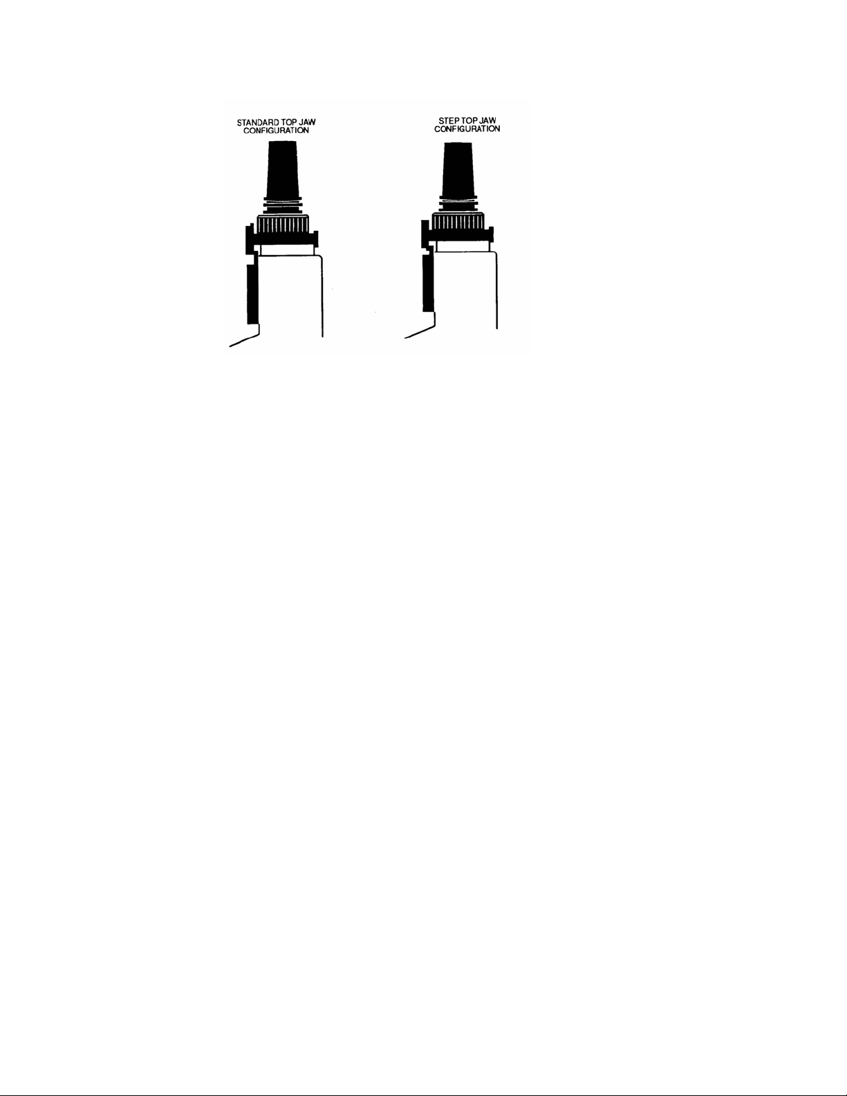
6. Vise Jaws
Choosing the correct upper vise jaws. For most key cutting work the upper jaw can remain in the standard
configuration. In the standard configuration the entire “throat” of the bottom and top jaws is used.
Measuring from faces of the top and bottom vise jaws and into the throat of the jaws- you will measure
.142”. This throat dimension of .142” is how much of the key is consumed by the vise jaws when the key
is clamped. Most keys are rarely cut deeper than .142” from the back edge of the key blade.
Some padlock keys and some General Motors keys and Medeco Hi-Security keys have cuts deeper than
.142” from the back edge of the key blade. For these keys you have two choices to clamp the keys.
A) The old-fashion way. Use a pair of round wire shims made from Music Wire about .037” diameter
and about 1- ½” long. Place a wire shim in each vise jaw against the back edge and lay the key in front
of the shim- effectively pushing the key out of the vise jaws and clamping on the remaining .105” of
the key.
B) The“step” jaw way. Loosen the knurled knob securing the top vise jaw in place and flip the top
jaw over the step jaw side. Retighten the knurled knob securing the top vise jaw. You must do both
vise jaws for this to work.
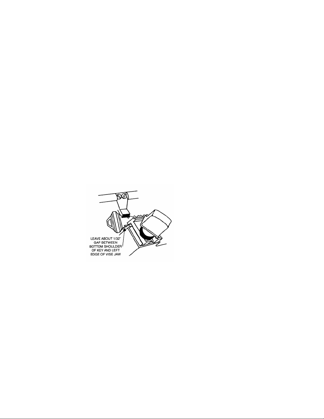
By opening the vise jaws just enough to slide the key in you will be making the key lay right in front of the
step portion of the top vise jaw effectively pushing the key out of the vise jaws and clamping on the
remaining .105” of the key. See Figure 2 below.

8
Figure 2
CHANGING THE TOP VISE JAWS
To change the top vise jaw unscrew the painted key-clamping knob a few turns. Unscrew the large
knurled knob located below the painted key-clamping knob a few turns. Slide out the top vise jaw. Look
for key cutting chips and brush them away before reinstalling the top vise jaw. Reinstall the top vise jaw in
the reverse order.
NOTE: When reinstalling the top vise jaw you should push on the face of the top vise jaw and hold it
against the vertical step on the bottom vise jaw. By doing this you will insure that the top vise jaw is
installed perfectly parallel to the bottom vise jaw. This is especially important when using the face of the
top vise jaw as a reference surface when cutting keys like Ford double-sided and when using the step jaw
Especially when cutting Medeco keys.
Always change both vise jaws to standard or step jaw configuration. If you change only one your depth
will be off either plus .037” or minus .037”. See figure 3 below
Check the knurled knobs securing the top vise jaws for tightness often and recheck the parallelism of the
top vise jaws- especially when using the step vise jaw configuration and when cutting keys such as Ford
double-sided.
TOP VISE JAW REPLACEMENT
Either top vise jaw may be replaced at any time. You do not have to buy top vise jaws in pairs. Inspect
your top vise jaws for uneven clamping and referencing surfaces. Replace when worn. Accelerated wear
occurs when you clamp double-sided steel keys such as Volkswagen. Clamping pre 1984- ½ Ford doubled
sided keys too far to the right into the vise jaw causes wear to the left edges of both the top and bottom vise
jaws. The damage is due to the “wedged” shaped milling of these keys as you approach the bow of the key.

9
BOTTOM VISE JAW REPLACEMENT
FIGURE 3
Remove the top vise jaws. The bottom vise jaws are secured by two #10-32 x ½” long socket head cap
screws. Use a 5/32” Allen hex wrench to remove the screws. If you have difficulty accesing the bottom
screw you may remove the top plate. See figure 4 below.
FIGURE 4
To remove the top plate you must first remove the key clamping knob assembly with the 3 piece radial
thrust bearing and the knurled knob. Use a 7/64” Allen hex wrench to remove 4 #6-32 x ½” long socket
head cap screws.
Remove bottom vise jaw from 1” diameter plunger. Wipe plunger and carriage surfaces clean with a lint-
free rag or paper towel. Bolt a new bottom vise jaw onto the plunger; loosely do not tighten the two screws
at this time. Use Sta-Lube Super White Multi-Purpose Grease (available in Auto Parts Stores). This is a
Lithium grease, Grade 2, 350° F min., and water resistant lubricant.
Coat all steel sliding surfaces (back side of bottom vise jaw and plunger and all aluminum mating surfaces
on the carriage). Also apply this grease to the 3/8” threaded hole in the plunger.
Gently slide the assembly into the carriage from the top. Snug up the two screws securing the bottom vise
jaw and check that the assembly slides up and down in the carriage- do not tighten the two screws at this
time.

10
Reinstall the top plate with the (4) #6-32 x ½ screws flush with the top of the top plate- but do no tighten
the four screws at this time. Remember to reinstall the top plate with its INDEX MARK in the same
location it was before. See figure 4 above for reference.
With your hand hold the top vise jaw on top of the top plate and at the same time raise up the bottom vise
jaw so the two vise jaw parts engage each other as if they were clamping a key. With your other hand grab
the edges of the top plate and pull it back until it contacts the short tabs on the open “horseshoe” end of the
top vise jaw. You want to take up as much of the slack between the top and bottom vise jaws as you can.
Now tighten the four #6-32 screws with your 7/64” Allen hex wrench readjust if necessary to get a good
fit.
You may now reinstall the knurled knob, 3-piece radial thrust bearing (please clean it first) and key clamp
knob assembly – you may secure the top vise jaw in place with the knurled knob at this time.
You will secure the bottom vise jaw now. Before tightening the two #10-32 screws- use the key clamp
knob to close vise jaws together with moderate force without a key. Now tighten the two #10-32 screws
with your 5/32” Allen hex wrench. Loosen the key clamp knob a few turns and push down on it to open
the vise jaws. You have created a matched pair of vises on your key machine that are about as good as they
were when the machine was new.
7.Top Shoulder Key Gauging
FIGURE 5
Standard cylinder keys should always be Top Shoulder Gauged. Use the machine’s full-function flip-up
key gauges. We do not recommend bottom shoulder gauging because key blank manufacturers do not
always maintain a reliable correlation between bottom and top shoulder positions on the key blanks they
make. See figure 5 above.
Always remember to flip DOWN your key gauges before cutting a key. Failure to do so may damage the
key gauge and key gauge shaft with your cutter wheel.

11
8.Clamping Keys
Open the vise jaws only wide enough to slide the key in. With the key in all the way into the “throat” of
the vise jaws- put your index finger against the key blade as shown below and with moderate force against
the key into the vise jaw gently slide the key left and right a few times (about 1/8” will do) to “seat” the key
into the vise jaws. With the bottom shoulder of a standard cylinder key about 1/32” away from the left
edge of the vise jaws CLAMP the key with the key clamp know-still pressing against the blade of the key
with your finger as you tighten the key clamp knob. See figure 6.
FIGURE 6
We recommend that you clamp the Blank in the right vise jaw first-then flip up the full-function key gauges
and clamp the customer (original) key in the left vise jaw using your finger-following the same procedure
outlined directly above. See figure 7 below
When both keys have been properly gauged and clamped in the vise jaws REMEMBER to flip down the
full-function key gauges before attempting to cut the key. Failure to flip down the key gauges may damage
the key gauge and key gauge shaft with the cutter wheel.
FIGURE 7
CLAMPING (Ford double-sided keys)
Keys such as Ford double-sided ignition and door do not have a top shoulder to gauge from.
Open the vise jaws ONLY enough to slide in the thinnest part of the key. Slide in the key blank and allow
the full thickness “ridge” of the key contact the face of the vise jaw.
Clamp the key into the vise jaws so that its cuts are approximately centered in the vise jaws.

12
Ignition key “ridge” will contact the face of the TOP vise jaw. See figure 8 below.
Door and trunk key “ridge” will contact the face of the BOTTOM vise jaw. See figure 8 below.
See figure 8 below for proper insertion of keys into vise jaws.
FIGURE 8

13
9.Tip Gauging (Ford double-sided)
Operate the full-function key gauges by rotating the key gauge shaft towards you-then push to the right on
the key gauge shaft while continuing to rotate the key gauge until the key gauge aligns itself with the tip of
the key. See figure 9.
FIGURE 9
Always remember to flip DOWN your key gauges before cutting a key. Failure to do so may damage the
key gauge and key gauge shaft with the cutter wheel.
BEST and FALCON (behind the tip) key gauging
These keys must be gauged from a “tip” location that is behind the actual tip of the key, see figure 10.
Position the key in the vise so that the “tip” edge of the key is about 1/32” (or less) from the right edge of
the vise jaws. Operate the full-function key gauges by rotating the key gauge shaft towards you- then push
to the right on the key gauge shaft while continuing to rotate the key gauge shaft until the key gauge slides
past the actual tip of the key. Slowly release the key gauge shaft and allow the key gauge to rest on the
“tip” location that is behind the actual tip of the key. See figure 11.
Figure 10

14
Figure 11
10.Releasing The Carriage
For safety purposes- releasing the carriage requires two actions. With your right hand, push down gently
on the carriage’s large “tear-drop” knob just enough to move the carriage down reach around with your
thumb and index finger and grasp the small round black knob and pull it out – gently lift up on the carriage
a small distance and THEN let go of the small round black knob and continue positioning the carriage
where you want it to be (you will want to move the carriage to the beginning of the first cut nearest the bow
of the key). See figure 12 below.
Note: You will not be able to pull on the small black knob by itself to release the carriage. You are
required to push down on the carriage first-then pull out the small black knob to release the carriage.
Figure 12
ALWAYS REMEMBER to flip down your key gauges before cutting a key. Failure to do so may damage
the key gauge and key gauge shaft with the cutter wheel.
PLEASE … DON’T FORGET to turn off your key machine before removing a cut key and reloading
another blank.

15
LOCKING THE CARRIAGE BACK (After cutting a key)
Push DOWN on the carriage’s large “tear-drop” knob until the carriage “clicks” into the locked position.
11. ROTATING THE STYLUS (Medeco duplication)
The RY256’s stylus can be rotated from the “center” (straight up) position- to the left or to the right.
Rotating the stylus is accomplished by moving the small black knob attached to the stylus either to the left
or to the right of “center” position. There is no locking action required to “lock” the stylus in position-
instead we provide an efficient ball and spring “detent” device that you can “feel” when moving the stylus
from position to position. See figure 13 below
CENTER CUT POSITION- Straight UP
LEFT CUT POSITION- Move the small black knob to the right.
RIGHT CUT POSITION- Move the small black knob to the LEFT.
FIGURE 13
12. CUTTING STANDARD KEYS
Leave stylus in the CENTER position-straight UP
CUTTING MEDECO KEYS
A) Cut all CENTER cuts first.
B) Cut all Left cuts second.
C) Cut all RIGHT cuts third.

16
13.ROTATING THE CUTTER HEAD (Medeco duplication)
The cutter head must always be rotated in the same direction as the stylus. To rotate the cutter head-Turn
the large black round knob and shaft assembly until you “feel” the shaft “detent” (or loosen) into position.
It does not matter if you turn the large black knob and shaft in the left direction or in the right direction.
You cannot undo the shaft from the machine buy turning it.
Once you have turned the large black knob and shaft assembly to the “detent” (loose position) you may
rotate the cutter head to the angled position of your choice-Left, Right or Center. Grasping the shaft just
below the large black knob and rotating the entire cutter head assembly with your wrist can accomplish
rotating the cutter head. When you are in position you will “feel” the cutter head assembly “fall” into
position. Once the cutter head assembly is in position you may turn the large black knob about 1/ 2 turn to
lock it in place before cutting. It does not matter if you turn the large black knob and shaft 1/ 2- turn in the
left direction or in the right direction. See figure 14.
CENTER CUT POSITION—Straight UP
LEFT CUT POSITION—Rotate the cutter head assembly to the RIGHT.
RIGHT CUT POSITION –Rotate the cutter head assembly to the LEFT.
FIGURE 14

17
CUTTER HEAD LABEL
The label in figure 15 is affixed to your motor-near the large black knob and shaft assembly.
FIGURE 15
14. LOCK THE CUTTER HEAD.
The cutter head must be LOCKED in position when cutting keys –Center, Left, or center Right.
PLEASE … DON’T SLAM the cutter head to the Left or Right positions. We’ve provided solid stops in
addition to the ball and spring “detent” mechanism for two reasons: To prevent over rotation of the cutter
head assembly and to provide you an easy way to learn where the left and Right positions are when you
first get your machine.
ALWAYS TURN OFF your key machine before rotating the cutter head from position to position when
cutting keys.
SWITCH “ON” YOUR MACHINE
The power switch is located at the top, right rear of the machine-near the motor. See figure 16.
To switch ON push the switch to the rear.
To switch OFF pull the switch forward.

18
FIGURE 16
15. CUTTER SHAFT LOCK
To remove the cutter you must lock the cutter and cutter shaft in position before using a wrench to remove
the cutter.
Press DOWN firmly on the cutter shaft lock (small round black knob). While holding the knob down rotate
the cutter by hand until the cutter shaft lock “clicks” into position. When turning the cutter by hand there is
only ONE locking position. You may now proceed with removing the cutter shaft lock nut and the cutter.
PLEASE… DON’T FORGET to pull UP on the cutter shaft lock when you are finished reinstalling the
cutter wheel. Pulling UP on the cutter shaft lock releases the cutter and cutter shaft from the locked
position. Failure to unlock the cutter when attempting to cut a key will result in no rotation of the cutter.
Please note-However-the motor may be powerful enough to slip the belt and permanently damage it by
wearing a flat spot on the belt.
16. Removing/Replacing the Cutter
REMOVING THE CUTTER
The cutter wheel is secured to the cutter shaft with a LEFT-HAND NUT. You must turn the nut to
the RIGHT (facing the cutter wheel) to remove it. See figure 17 below
Remember to LOCK the cutter before removing the cutter wheel.
Use a 1” open-end or hex wrench to remove the Left-Hand Nut. See figure 17.

19
Figure 17
REPLACING THE CUTTER
Before your replace the cutter - clean off any cuttings from the cutter shaft with a clean rag. Apply a
small of white grease to the cutter shaft face, shank, and threads before installing the cutter wheel and
Left-Hand Nut.
DON’T OVERTIGHTEN the cutter wheel nut - The Left-Hand Nut is self-locking as you use it.
Overtightening the cutter wheel nut may make it harder to remove later and may result in damaging the
cutter shaft lock or cutter shaft pulley.
PLEASE… DON’T FORGET to pull UP on the cutter shaft lock when you are finished reinstalling
the cutter wheel. Pulling UP on the cutter shaft lock releases the cutter and cutter shaft from the locked
position. Failure to unlock the cutter when attempting to cut a key will result in no rotation of the
cutter. Please note however the motor may be powerful enough to slip the belt and permanently
damage it by wearing a flat spot on the belt.
17. Depth Adjustment
Depth is adjusted at the backside of the stylus.
To adjust the depth you will need.
1/8” Allen Hex Wrench
7/16” Wrench
Piece of writing paper cut to approximately 1” x 4”.
Two identical key blanks – measure blade width with micrometer or dial calipers and select
two that match.
Before you begin please make sure that both top vise jaws are in the standard configuration. See figure
18 below.

20
FIGURE 18
Depth is adjusted by moving the stylus forward or backward by means of a hardened, fine threaded
Allen set screw. The adjustment is secured by 7/16” Hex Jam Nut. See figure 19 below.
To begin the adjustment you must loosen the 7/16” Hex Jam Nut-do not remove it.
With your 1/8” Allen Hex Wrench-turn the set screw into the housing to make the stylus move
forward toward the front of the machine. About 1 turn should be enough.
FIGURE 19
Secure the two matched key blanks - one in each vise jaw. Please note: Clamp the keys into the vise
jaws with about 1/32” gap between the bottom shoulder of the key and the left-side edge of the vise
jaws. DO NOT bottom shoulder the keys into the vises - there may be a small radius in the corner of
the key blank’s blade and the bottom shoulder area. Clamping in this area may ANGLE the key blank
in the vise and throw off your adjustment.
With the keys clamped in the vises and with the stylus adjusted forward about 1 turn - carefully release
the carriage and position it so the key in the left vise jaw LIGHTLY contacts the stylus about in the
middle of the key blank’s blade.
Observe that the cutter wheel misses the key blank in the right vise by carefully turning the cutter
BACKWARDS by hand - the cutter teeth should miss the blade. The reason for turning the cutter
backwards is to prevent any cutter teeth from removing material off the key blank’s blade before you
Table of contents
Other Rytan Disc Duplicator manuals