Rytan RY456 User manual

INCORPORATED
RYTAN, INC. RESERVES THE RIGHT TO MAKE CHANGES WITHOUT NOTICE. PRICES MAY VARY FROM YOUR DISTRIBUTOR.
READ AND UNDERSTAND THIS OPERATORS MANUAL AND BECOME
FAMILIAR WITH YOUR NEW MACHINE BEFORE YOU START CUTTING KEYS.
Model RY456
OPERATORS MANUAL
Rytan Mode RY456 Semi-Automatic Key Dup icating Machine with 4-Way Jaws
for Cy inder Keys and Automotive Keys and Medeco
CLAMPS MORE KEYS
NEW CUTTER AND STYLUS CUTS GM AND KWIKSET TITAN KEYS
BUILT IN MICRO-ADJUST STYLUS
Rytan Products are Designed and Manufactured in the U.S.A.
RYTAN, INC. - 1648 W. 134th St. Gardena, CA 90249 (800) 447-9826 - (310) 212-6002
NEW 4-WAY JAWS
CLAMPS MORE KEYS
2-WAY
3-WAY
1-WAY
4-WAY
Wire Brush
Kit
INCLUDED!
RY20005 Complete
Carriage Assembly
ADD 380.00
Key Gauge Protector
INCLUDED!
KEY DUPLICATING
MACHINE w/Medeco Capacity
WITH 4-WAY JAWS
ADJUSTABLE STYLUS
.0005Accurate
(1 2 thousanth!)
INCLUDED!
NOW YOU CAN CUT KEYS LIKE GM AND KWIKSET
TITAN FIRST CUT WITH ONE SIDE STRAIGHT,
LIKE THE FACTORY!
NEW CUTTER RY20030 AND RY456276 STYLUS
CUTS MORE KEYS
STRAIGHT
RY39 Auxillary Lamp Kit
ADDITIONAL COST ADD
53.50

TABLE OF CONTENTS
1. INTRODUCTION
2. GETTING STARTED
3. SAFETY RULES
4. MOUNTING THE MACHINE
5. CUTTING STANDARD KEYS
6. CUTTING DEEP CUTS
7. VISE JAWS
. TOP SHOULDER GAUGING
9. CLAMPING KEYS
10. BEST and TIP GAUGING
11. RELEASING THE CARRIAGE
12. CUTTER SHAFT LOCK
13. REMOVING/REPLACING CUTTER
14. DEPTH ADJUSTMENT
15. SPACE ADJUSTMENT
16. KEY GAUGE ADJUSTMENT
17. CARRIAGE OVER TRAVEL ADJ.
1 . MAINTENANCE
19. TROUBLESHOOTING
20. CUSTOMER INFORMATION
21. WARRANTY
22. PARTS BREAKDOWN
2
....................3
....................3
....................3
....................4
....................5
....................5
....................6
....................7
....................
....................9
....................9
....................10
....................11
....................13
....................14
....................15
....................16
....................16
....................1
....................24
....................24
....................24

1. INTRODUCTION
Thank you for purchasing our American Made, Rytan, Inc., Model RY45 , universal key duplicating
machine. Your new key machine has been designed and built with heavy-duty components designed
for the most demanding shop and service vehicle use. As you become familiar with your new
machine you will find a new ease and confidence in key cutting. Discover the smooth and natural
interaction between machine and operator, resulting from careful design and placement of the
operating controls. We are confident you will profit greatly from this quality built versatile key
machine.
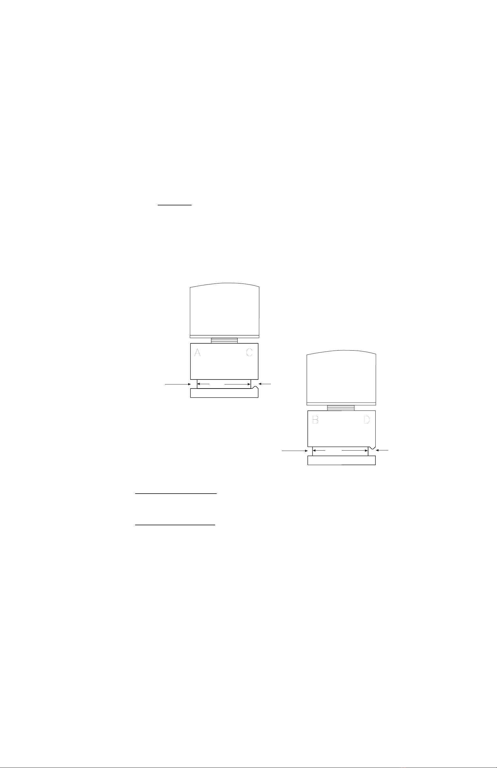
Your new RY45 key duplicating machine is made similar to the RY25 RAMM semi-automatic
key machine. The Stylus on the RY45 key machine is 100% adjustable to better than ½-thousanths
of an inch (0.0005), and can be re-set to 0 at any time.
Use your machine to cut standard cylinder keys and U.S. Foreign automobile keys and Medeco.
2. GETTING STARTED
Please take time now to read and understand this manual thoroughly before you start cutting keys.
Maintain this owners manual and review it often, and make it available to others who will use this
machine.
Do not attempt to operate this machine until you have read it thoroughly and understand completely
all instructions, rules, etc. contained in this manual. Failure to comply can result in accidents in-
volving fire, electric shock, or serious personal injury.
3. SAFETY RULES
A. Know your machine. Read the owners manual carefully. Learn its applications and
limitations as well as specific operational hazards peculiar to this machine.
B. Guard against electrical shock by preventing body contact with grounded surfaces. Examples:
Pipes and metal work tops.
C. Keep guards in place at all times.
D. Keep your work area clean. Cluttered areas and benches invite accidents.
E. Avoid dangerous environment. Dont use this machine in damp or wet locations. Keep
your work area well lit.
F. Keep children away. All visitors should be kept a safe distance from work area. Do not
let visitors contact machine or power cord.
G. Do not force the machine. It will do the job better and safer at the rate for which it was
designed. Always maintain a sharp cutter wheel on the machine.
H. Use the machine for what it was designed. Dont use the machine for anything but the key
blanks for which it was intended. Cutting steel keys is not recommended.
I. Wear proper apparel. For example: No loose clothing or jewelry to get caught in moving
parts. Operators without properly restrained long hair MUST NOT operate any type of machinery,
including key machines. Long hair can get caught in moving (rotating) machinery parts.
J. Use safety glasses. Flying chips, improperly secured key blanks and broken cutter wheel
teeth can injure the eye if not properly protected.
K. Dont abuse cord. Never yank cord to disconnect from receptacle. Keep cord from heat,
oil and sharp edges. Never remove the ground connection from the plug. If you use a two wore
adapter be sure to properly connect the ground wire. NEVER CUT OFF THE GROUND TERMINAL
FROM THE MACHINES POWER PLUG!
3

L. Secure keys properly in vises. Dont hold key head for support when cutting. If it doesnt
clamp properly, dont try to cut it!
M. Maintain a sharp cutter wheel. dull cutter wheel is not only inefficient but dangerous.
dull cutter wheel can produce excessive cutting force on a key blank and exceed the machines vise
jaws clamping force to a point where the key blank could be ripped out of the machine.
N. Disconnect machine. When not in use, during servicing, or when changing cutter wheel and
accessory brush always disconnect the machine form its electrical power source.
O. Remove servicing wrenches. Remove all service tools from the machine before turning it
on.
P. lways turn off machine. fter cutting a key, turn off the machine before removing a cut
key and clamping another fresh blank.
Q. lways lock carriage back. fter cutting a key, turn off the machine and lock the carriage
back to prevent accident or injury.
R. Outdoor use. When machine is used outdoors, use only extension cords suitable for outdoors
and that have a built-in third wire and ground terminal. NEVER CUT OFF THE GROUND TERMIN L
FROM THE M CHINES POWER PLUG!
S. Keep hands away from cutter and key blank. Keep hands away from rotating cutter. Do
not reach underneath or around cutter or key blank when cutter is rotating. Do not attempt to remove
key blank or key blank material while cutter is rotating.
T. Never use machine in an explosive atmosphere. For example, if your machine is in a service
vehicle with a fuel leak or spill, switching on the machine could ignite the fumes.
NOTE: FL MM BLE SOLVENT SPILL IN YOUR SHOP OR V N IS EQU LLY D NGEROUS!
U. Inspect machine cord periodically. If damaged, repair at once.
V. Keep hands dry, clean and free from oil and grease.
W. Stay alert. Watch what you are doing and use common sense. Do not operate machine when
you are tired.
X. Do not use machine if switch does not turn the machine ON and OFF.
Y. Drugs, lcohol, Medication. Do not operate machine while under the influence of drugs,
alcohol, or any medication.
Z. The operation of any key machine can result in foreign objects being thrown into the eyes,
which can result in severe eye damage. lways wear safety glasses or eye shields before commencing
key machine operation. We recommend wide vision safety mask for use over spectacles or standard
safety glasses.
. Save these instructions.
4. MOUNTING THE MACHINE
Drill two oversized ½ holes in your bench top to mount the machine. Use ½ 13 bolts from your
local hardware store. Carefully turn the machine up-side-down and measure the spacing of the two
tapped holes on the bottom of your machine (be careful not to set the machine on the power switch).
Turn the machine right-side-up and place the machine where you want it on your work bench. Mark
the bench and drill your holes.
4

5. CUTTING STANDARD KEYS
A. Most key clamping requirements use the standard jaw A configuration. Jaw requirements
- to make deeper cuts in small keys or to clamp other types of keys simply loosen the key clamp knob
a few extra turns and lift-and-turn the jaw assemblies from A to B to C to D.
B. Keys are always gauged with the full-function flip-up key gauges. We do not recommend
bottom shoulder gauging because key blank manufacturers do not always maintain a reliable correlation
between bottom and top shoulder positions on the key blanks they make.
C. Always remember to flip down your key gauges before cutting a key. Failure to do so will
prevent the key from being cut by the cutter wheel.
D. Always cut keys from Bow-to-Tip. NEVER MAKE YOUR FIRST CUT FROM TIP-TO-
BOW.
The RY456 is specifically designed to cut most cylinder keys U.S. and Foreign automotive keys and
Medeco by operating the machines stick-shift lever SMOOTHLY from Right-to-Left. The key will
be cut properly starting at the Bow and ending at the tip of the key. It is O.K. to make a cleanup cut
back to the bow of the key ONLY after the key has already been cut from Bow to tip.
NOTE: If an excessive amount of key blank material is removed on the cleanup cut (second cut) your
cutter may need replacing or re-sharpening. Rytan can sharpen your dull cutter.
6. CUTTING DEEP CUTS IN SMALL KEYS
A. Most key clamping requirements use the standard jaws A configuration. If you are making
deep cuts you may have to rotate to the B jaw configuration. You must loosen the painted key
clamping knobs a few turns turn the vise and retighten.
Make sure your vise jaws are clean (with no chips in the way) and as you secure the vise jaw on to
your key - be sure to push the key into the jaw firmly and make sure they remain flat and parallel into
the vise jaws when tightening the large painted key clamp knob.
When clamping keys in the jaws be sure to open the jaws ONLY enough to slide the key in place.
Please see elow for more Vise Jaw information.
B. Keys are always gauged with the full-function flip-up key gauges.
C. Always remember to Flip Down your key gauges before cutting a key. Failure to do so will
not cut the key.
D. Switch ON your machine and operate the stick-shift lever until the stylus is right over the
left edge of the first cut closest to the bow of the key gently press down on the carriage with the black
tear-drop hand then reach down and pull out the carriage release (small round black knob) and release
the carriage. You may ease up on the carriage and manipulate the carriage controls to make a smooth
gentle cut down the left edge of the first V cut in the key to the last cut on the tip of the key - cutting
all cuts on the key.
E. You may want to reverse the direction of the carriage and make a clean-up cut back to the
bow of the key.
F. Push down and lock back your carriage. Turn OFF the machine.
NOTE: CUTTING STEEL KEYS IS NOT RECOMMENDED.
Cutting steel keys will accelerate cutter wear. Some steel keys will ruin your cutter wheel with just
one pass.
NOTE: Some automotive presentation keys are made of Hardened Steel and can ruin the cutter wheel instantly!
Dont be fooled by the decorative Gold Brass or Silver plating on these keys.
5

Suggestion: Keep a small magnet near your key machine to identify steel keys. Before cutting a
steel key try filing a small groove where one of the deeper cuts will be made if the key wont file
easily it wont cut any better in your key machine and will most likely ruin your cutter!
. VISE JAWS
Choosing the correct vise jaw. For most key cutting work the jaws can remain in the standard A
configuration. In the standard configuration the entire throat of the jaws is used. Measuring from
the front faces of the A vise jaw and into the throat of the jaws you will measure .142. This
throat dimension of .142 is how much of the key is consumed by the vise jaws when the key is
clamped. Most keys are rarely cut deeper than .142 from the back edge of the key blade.
Some padlock keys and some General Motors keys have cuts deeper than .142 from the back edge
of the key blade. For these keys you can flip your vise jaws to B. Loosen the vise jaw a few turns,
flip the vise jaws to B and retighten the large painted knob. You must do both vise jaws for this
to work. Your B key machine vise jaws now have a throat of .105 to clamp the key.
CHANGING THE VISE JAW
Your new jaws can be rotated from the A jaws to B, C, or D vise jaws by just turning them.
VISE JAW REPLACEMENT
Either vise jaw assembly may be replaced at any time. Inspect your vise jaws for uneven clamping and
referencing surfaces. Replace when jaws appear worn. Accelerated wear occurs when you clamp double-
sided steel keys such as Volkswagen. Clamping pre 1984- ½ Ford double-sided keys too far to the right into
the vise jaws may cause wear to the left edges of both top and bottom vise jaws. The damage is due to the
wedged shaped milling of these keys as you approach the bow of the key. This can be observed if you open
the vises only enough to insert the key.
6
Fig.1
STANDARD A JAW
(0.142 deep) C JAW
(0.260 deep)
D JAW
(0.260 deep)
Fig.2
STANDARD B JAW
(0.105 deep)

VISE JAW REPLACEMENT
Vise jaws (cartridges) are replaced in pairs as an assembly, a matched set consisting of (one top jaw
and one bottom jaw), you will need two sets for your key machine. You will disassemble and re-
install the old plungers, springs, and screws. Or you can buy a complete set with the plunger, top
jaw, bottom jaw, screws and springs. imply drop the (cartridges) in place, you will need two
cartridges.
Coat all steel sliding surfaces with a light coating of grease when installing the vises.
8. TOP SHOULDER KEY GAUGING
tandard cylinder keys should always be top shoulder gauged. Use the machines full-function flip-
up key gauges. We do not recommend bottom shoulder gauging because key blank manufacturers
do not always maintain a reliable correlation between bottom and top shoulder positions on the key
blanks they make.
Always remember to flip DOWN your key gauges before cutting a key. Failure to do will prevent your key
machine from cutting the key.
7
Fig. 4
RY10054 Key Gauge
Protector (red)
RY10049Key Gauge Shaft
RY9278 Vi yl Cap (red)
Key Gauge
RY10050 Left-Ha d Key Gauge
RY10048 Right-Ha d Key Gauge
Key Vise K ob
(with) RY82
3-piece Thrust
Beari g Assy.
Top 4-way Jaw
Bottom 4-way Jaw
Fig.3
CLAMPS MORE KEYS
NEW 4-WAY VISES
A
B
C
D
RY20080 KNOB WITH SHAFT ASSY.
RY82 3-PC THRUST BEARING ASSY.
RY20089 TOP VISE, JAW 4-WAY
RY20047 BOTTON VISE, 4-WAY
RY20046 VISE PLUNGER

1. CLAMPING KEYS
Open the vise jaws only wide enough to slide the key in. With the key all the way into the throat
of the vise jaws - put your index finger against the key blade and with moderate for e against the
key in to the vise jaw, gently slide the key left and right a few times (about 1/8 will do) to seat
the key into the vise jaws. With the bottom shoulder of a standard ylinder key is about 1/32 away
from the edge of the vise jaws CLAMP the key with the key lamp knob ontinue pressing against
the blade of the key with your finger as you tighten the key lamp knob.
When both keys have been properly gauged and lamped in the vise jaws REMEMBER to flip down
the full-fun tion key gauges before attempting to ut the key. Failure to flip down the key gauges
will prevent you key ma hine from utting the key.
KEY CLAMPING . . . (Ford double-sided keys)
Keys su h as Ford double-sided ignition and door do not have a top shoulder to gauge from.
Open the vise jaws A vises ONLY enough to slide in the thinnest part of the key. (See Fig. 5 &
6) Slide in the key blank and allow the full thi kness ridge of the key to onta t the fa e of the
vise jaw.
Clamp the key into the vise jaws so that its uts are approximately entered in the vise jaws.
Ignition key ridge will onta t the fa e of the TOP vise jaw.
Door and trunk key ridge will onta t the fa e of the BOTTOM vise jaw. See Fig. 5 & 6 below..
Use vise jaw to cut Medeco.
Keys su h as Chi ago double sided and others should use vises D and C to lamp into the groove
near the enter of the blank. (See Fig. 7 & 8)
TIP OR BEHIND THE TIP KEY GAUGING.
Operate the full-fun tion key gauges by rotating the key gauge shaft toward you - then push to the right on
the key gauge shaft while ontinuing to rotate the key gauge until the key gauge aligns itself with the tip of
the key. Or behind the TIP as in Best keys.
8
BD
CA
AC
CA
Key must fit
against Top Jaw
Key must fit
against Bottom Jaw
Key ridge on
Bottom side
Key ridge on
Top side
Fig. 8
Fig. 7
Fig. 6
Fig. 5

Always remember to flip DOWN your key gauges before cutting a key. Failure to do so will prevent
the key from being cut.
1 . BEST AND FALCON (BEHIND THE TIP) KEY GAUGING
These keys must be gauged from a tip location that is behind the actual tip of the key. Position
the key in the vise so that the tip edge of the key is about 1/32 (or less) from the right edge of
the vise jaws. Operate the full function key gauges by rotating the key gauge shaft toward you -
then push to the right on the key gauge shaft while continuing to rotate the key gauge shaft until the
key gauge slides past the actual tip of the key. Slowly release the key gauge shaft and allow the key
gauge to rest on the tip location that is behind the actual tip of the key. See figure 11 and figure
12.
Always remember to flip DOWN your key gauges before cutting a key. Failure to do so will prevent
the key from being cut.
11. RELEASING THE CARRIAGE
For safety reasons - releasing the carriage requires two actions. With your right hand, push down
gently on the carriages large teardrop knob just enough to push the carriage down a small distance.
While holding the carriage down reach around with your thumb and index finger and grasp the small
round black knob and pull it out and hold it there. When the small round black knob is pulled out -
gently lift up on the carriage a small distance and THEN let go of the small round black knob and
continue positioning the carriage where you want it to be (you will want to move the carriage to the
beginning of the first cut nearest the bow of the key).
NOTE: You will not be able to pull the small black knob by itself to release the carriage. You must
push down on the carriage first then pull out the small black knob to release the carriage. Se
ALWAYS REMEMBER to flip down your key gauges before cutting a key. Failure to do so will
prevent the key from being cut.
PLEASE. . . DONT FORGET to turn off your key machine before removing a cut key and reloading
another key blank.
LOCK THE CARRIAGE BACK (after cutting a key). Push DOWN on the carriages large teardrop
knob until the carriage clicks into the locked position.
9
Fig. 10

SWITCH ON YOUR MACHINE
The power switch is located at the lower right, front of the machine. See figure 12.
To switch ON pull the power switch up.
To switch OFF push the power switch DOWN.
12. CUTTER SHAFT LOCK
To remove the cutter ou must lock the cutter and cutter shaft in position before using a 1 wrench
to remove the cutter.
10
New Cutter will cut
straight on left side
of key cut
Adjustable Stylus
(.0005) one half
thousanth INCH
NEW 4-WAY VISES
CLAMPS MORE KEYS
2-WAY
3-WAY
1-WAY
4-WAY
Power Switch
UP ON
Down off
CUT STRAIGHT
Cutter
Shaft
LOCK
Fig. 12
Fig. 11
New Cutter will cut
straight on left side
of key cut
Adjustable Stylus
(.0005) one half
thousanth INCH
NEW 4-WAY VISES
CLAMPS MORE KEYS
2-WAY
3-WAY
1-WAY
4-WAY
Power Switch
UP ON
Down off
CUT STRAIGHT

Press DOWN firmly on the cutter shaft lock. While holding the lever down - rotate the cutter by
hand until the cutter shaft lock clicks in to osition. When turning the cutter by hand there is only
ONE locking osition to be found. Once the cutter shaft lock is fully de ressed - Hold it There.
You may now roceed with removing the cutter shaft lock nut and the cutter.
PLEASE . . . DONT FORGET to ull UP on the cutter shaft lock when you are finished reinstalling
the cutter wheel. Pulling UP on the cutter shaft lock releases the cutter and the cutter shaft from the
locked osition. Failure to unlock the cutter when attem ting to cut a key may result in no rotation
of the cutter. Please note - the motor may be owerful enough to sli the belt and ermanently
damage it by wearing a flat s ot on the belt.
13. REMOVING/REPLACING THE CUTTER
REMOVING THE CUTTER
The cutter wheel is secured to the cutter shaft with a LEFT-HAND NUT. You must turn the nut to the
RIGHT (facing the cutter wheel) to remove it.
11
R
Y
2
0
0
3
0
C
U
T
T
E
R
INCORPORATED
UNDO
LEFT-HAND THREAD
FIG. 13

Remember to LOCK the cutter before removing the cutter wheel.
Use a 1 open-end or he wrench to remove the Left-Hand Nut. See Fig. 13.
REPLACING THE CUTTER
Before your replace the cutter - clean off any cuttings from the cutter shaft with a clean rag. Apply
a small amount of grease to the cutter shaft face, shank, and threads before installing the cutter wheel
and Left-Hand Nut.
DONT OVERTIGHTEN the cutter wheel nut - The Left-Hand Nut is self tightening as you use
it. Overtightening the cutter wheel nut may make it harder to remove later and may result in damaging
the cutter shaft lock or cutter pulley later when you remove the cutter at a later date.
14. DEPTH ADJUSTMENT
12
Strike Cutter Shaft lightly to nudge cutter
to its new position. NOTE: You can strike
the other end of the cutter shaft to nudge
the cutter in the other direction.
Key Gauge
ial
Key Gauge
CARRIAGE
Over-travel

Depth is adjusted at the back end of the stylus.
14. DEPTH ADJUSTMENT
To adjust the depth you will need.
vPiece of writing paper cut to approximately 1 x 4.
vTwo identical key blanks measure blade width with micrometer or dial calipers and select
two that match.
Before you begin please make sure that both vise jaws are in the standard A configuration.
Depth is adjusted by moving the stylus forward or backward by means of an adjustment dial located at the
back of the stylus.
Secure the two matched key blanks - one in each vise jaw. Please note: Clamp the keys into the vise jaws
with about 1/32 gap between the bottom shoulder of the key and the left-side edge of the vise jaws. DO
NOT bottom shoulder the keys into the vises - there may be a small radius in the corner of the key blanks
blade and the bottom shoulder area. Clamping in this area may ANGLE the key blank in the vise and throw
off your adjustment by cutting to shallow near the key head.
With the keys clamped in the vises and with the stylus adjusted forward about 1 turn - carefully release the
carriage and position it so the key in the left vise jaw LIGHTLY contacts the stylus about in the middle of
the key blanks blade.
Observe that the cutter wheel missed the key blank in the right vise by carefully turning the cutter BACKWARDS
by hand - the cutter teeth should miss the key blank blade. The reason for turning the cutter backwards is
to prevent any cutter teeth from removing material off the key blanks blade before you make your adjustments.
Turning the cutter backwards will bump the key blank without cutting it - if the stylus was not adjusted
forward enough to miss the key blank.
Upon verifying that the cutter wheel misses the key blank you may switch ON your key machine.
Take the 1 x 4 piece of writing paper you made earlier and hold one end of it between the spinning cutter
wheel and the blade of the key blank.
Use your hand to slowly and carefully turn the Dial at the same time we recommend that you slowly move
the 1 x 4 piece of paper from side to side along the blade of the key blank to assist you in detecting when
the cutter wheels teeth first contact the paper. When the cutter wheel first contacts the paper the paper will
be shaved almost without any sound you must back off the stylus very slowly for this to work.
Once you have the cutter wheel touching the paper you may slow down the procedure to very small increments,
1 number at a time - each time moving the piece of paper from side to side in front of the spinning cutter
wheel. Stop when the piece of paper is cut through to the last few fibers. You have now accurately adjusted
the depth of cut on your key machine.
13
New Cutter will cut
straight on left side
of key cut
Adjustable Stylus
(.0005) one half
thousanth INCH
2-WAY
3-WAY
1-WAY
4-WAY
NEW 4-WAY VISES
CLAMPS MORE KEYS
Cutter
Shaft
LOCK
Power Switch
UP ON
Down off
Fig. 15
CUT STRAIGHT

Verify by switching ON the machine and verifying that the cutter wheel just ticks the blade of the key blank.
We recommend moving the machines stick shift lever very slightly to the right and at the same time listening
to the cutter wheel for the very faint ticking sound of the cutter wheel teeth barely grazing the key blank. DO
NOT go back and forth over the same spot! If you use the same spot more than once your stylus will burnish a
spot on the key blank that is ever so slightly lower than the rest of the key blank.
Switch OFF the key machine.
1. SPACE ADJUSTMENT
Never adjust the spacing without first adjusting DEPTH. If the depth adjustment is not right then spacing will
not be right.
Spacing is adjusted by moving thestylus holder left or right. The stylus holder is secured to the machines main
housing by two 1/4 20 Socket Head Cap Screws and washers.
To adjust the spacing you will need:
v3/16 Allen Hex Wrench
vTwo identical Key Blanks
vSmall Plastic Mallet
Before you begin please make sure that both top vise jaws are in the standard A configuration.
Stack the two identical key blanks one on top of each other and clamp them in the right hand vise jaw. Be sure to
top shoulder gauge them with the machines flip up full function key gauges leave about 1/32 gap between the
bottom shoulder of the keys and the left side edge of the vise jaws. DO NOT bottom shoulder the keys into the
vise there may be a small radius in the corner of the key blanks blade and bottom shoulder area. Clamping in
this area may ANGLE the key blank in the vise jaw and throw off your adjustment. There should be NO key blanks
in the left vise jaw for this part of the procedure.
DO NOT FORGET to flip down your key gauges. Failure to do so may result in damage to the key gauge and
key gauge shaft by the cutter wheel.
Switch ON the key machine and carefully release the carriage and position it so the cutter wheel will make a cut
in about the middle of the blade of the key blanks. Hold the machines stick shift lever steady and carefully make
a straight V cut into the two piece key blank stack about 1/8 deep it is important to do this operation without
moving the carriage sidewise by the slightest amount.
Pull back the carriage to the locked position and switch OFF the key machine.
Remove the two key blanks from the right vise jaw Do Not Mix Them Up.
Reinstall the TOP key blank in the Right vise jaw with about 1/32 gap between the bottom shoulder of the key
and the left edge of the vise jaw.
Install the BOTTOM key blank in the left vise jaw flip up the machines full function key gauges and carefully
top shoulder guard the left key to the key in the right hand vise jaw.
Without turning ON the motor, carefully release the carriage and align the left hand blanks V cut with the
machines stylus the V cut in the key blank in the right hand vise jaw should fall into place around the V
profile of the cutter wheel.
Use your hands to carefully turn the cutter wheel BACKWARDS to verify that the cutter wheels teeth do not touch
the V cut in the right hand key blank.
Verify that the stylus is completely seated in the V cut in the left hand key blank. If it is and the cutter wheel will not
turn Backwards by hand, or the cutter wheel tick and V cut in the right hand key blank then spacing needs to be
adjusted.
14

Loosen the two 1/4-20 screws securing the stylus holder in place using your 3/16 Allen Hex rench---retighten
the two screws with LIGHT pressure. You want jut enough retightening pressure on the two screws to keep
the stylus holder in place so you cant move it with your hand--but you can move it with gentle to moderate
tapping with your small plastic mallet.
Turn the cutter BACK ARDS with your hand and observe which way you must move the stylus holder. Use
your small plastic mallet to nudge the stylus holder in the direction you want it to go. It is a good idea to
verify the cutter position in the V cut in the key after every tap of the small plastic mallet. Verify your
results by turning the cutter Backwards with your hand. Also, verify that the stylus is properly seated in the
V cut in the left-hand key. Adjust the position of the carriage using the machines stick-shift lever as
required to keep the stylus seated in the V cut in the key.
Continue with this procedure until you are satisfied witht he position of the stylus holder. Once you are satisfied
you may wish to turn ON your key machine and observe the spinning cutter wheel in the V cut in the key.
This test must only be done AFTER you have turned the cutter Backwards by hand and verify that no cutter
teeth will contact either side of the V cut in the key. ith the machine running you may want to slightly
nudge the stylus holder a little more before retightening the stylus holder.
Switch off the key machine. Tighten the two screws using the 3/16 Allen Hex rench.
IMPORTANT--Verify that your depth adjustment is correct and readjust if necessary. Refer back to Depth
Adjustment if necessary.
Spacing Adjustment is now complete.
IMPORTANT Verify that your depth adjustment is correct and readjust if necessary.
16. KEY GAUGE ADJUSTMENT
Stack two identical key blanks one on top of the other and clamp in the right-hand vise jaw. Be sure
to BOTTOM SHOULDER GAUGE them. DO NOT use the machines flip-up full-function key
gauges.
There should be NO key blank in the left vise jaw for this part of the procedure.
Switch ON the key machine and carefully release the carriage and position it so the cutter wheel will
make a cut in about the middle of the blade of the key blanks. Hold the machines stick-shift lever
steady and carefully make a straight V cut into the two-piece key blank stack - go all the way to
the carriages built-in over-travel stop and move the machines stick-shift lever to the LEFT making
a wide cut slightly more than ¼ wide.
Pull the carriage back and SWITCH OFF the key machine.
Remove the two key blanks from the right-hand vise jaw.
Reinstall one key blank in the Right vise jaw- use BOTTOM SHOULDER GAUGING. DO NOT
use the machines flip-up full-function key gauges.
Install the other key blank in the Left vise jaw - use BOTTOM SHOULDER GAUGING. DO NOT
use the machines flip-up full function key gauges.
NO flip up the machines full-function key gauges and place them in the wide grooves cut in the keys.
Adjust the key gauges as necessary by loosening the key gauges fastening screws - retighten the screws when
you are finished.
The key gauges now match the spacing of the vise jaws.
You MUST verify and readjust, if necessary, the machines spacing and adjustment.
15

17. CARRIAGE OVER TRAVEL DEPTH ADJUSTMENT
Your key machine is equipped with a depth over travel device. Its adjustment is important. The over
travel device prevents the cutter wheel from cutting into the vise jaws when there are no keys clamped
in the machine. Setting the depth over travel device too high will prevent deep cuts from eing made
- they will not get cut all the way down into the key lank.
To adjust the depth over travel you will need:
vSlot Head Screwdriver
v7/16 Wrench
vThree pieces of writing paper - cut to approximately 1 x 4 each.
Close oth vise jaws without keys in them. Release the carriage and position it so the stylus and
cutter wheel are in a out the middle of the vise jaws.
Loosen the 7/16 Hex Jam Nut on the front of the carriage.
Loosen the ¼ 20 slotted screw stud with your screwdriver. A out 1 turn should e enough.
O serve that the stylus is touching the face of the closed vise jaw.
Gently turn the slotted screw stud with your screwdriver in the clockwise direction and stop when
you feel the stud contact the key machines main housing. There is a 3 long hardened roll pin in
the machines main housing that the slotted screw stud will contact.
Turn the slotted screw stud an additional ¼ turn after contacting the roll pin the machines main
housing. The thread pitch is 20 which is approximately 12 thousands of an inch per ¼ turn. Tighten
the 7/16 Hex Jam Nut on the slotted screw stud - use moderate tightness.
After tightening the 7/16 not - check the gap etween the stylus and the face of the closed vise
jaws. Use three pieces of 1 x 4 writing paper you made earlier. They equal a com ined thickness
of a out 9 thousandths of an inch. Readjust if necessary.
IMPORTANT: Carriage over travel will work only when adjusted properly. The following things
can happen if the adjustment is not done properly.
a) If adjusted to low your cutter wheel may cut into the right-hand vise jaw.
) If adjusted to high your cutter wheel may not cut deep enough when cutting deep cuts in
keys.
c) Carriage over travel will not prevent cutting the right-hand top vise jaw if the top vise jaw
has come loose and has moved forward into the cutter. PLEASE check the tightness of the knurled
kno s OFTEN.
18. MAINTENANCE
UNPLUG YOUR MACHINE PRIOR TO MAINTENANCE
Your machine is time proven with good design, engineering and modern manufacturing practices.
You can service virtually anything on your machine yourself. There are no special tools, fixtures
or alignment jigs required to install the parts used in this key machine. Because Rytan manufactures
the machines in-house you are assured a supply of new replacement parts and updates for as long
as YOU want us to make the machines.
Keep your machine clean and lu ricated and it will remain a productive asset to your usiness for
a very long time.
16

MOTOR MOUNTING HARDWARE
LUBRICATION
UNPLUG YOUR MACHINE PROIR TO LUBRICATION
You do not need to lubricate the motor or the cutter shaft bearings - these ball bearing assemblies
are sealed and lubricated for their lifetime.
Lubricate your machine as often as you like. Use number 30 non-detergent motor oil. Apply oil
with a brush to all black oxide processed steel surfaces. After applying the oil let it stand overnight
and wipe the oiled parts dry the next day with a clean rag or soft paper towel. Turn the machine
over and lubricate the linkages that drive the carriage shaft left and right. WARNING: Do not turn
the machine over and set it on the Power Switch.
SUGGESTION: When lubricating the stick-shift drive linkages under the machine you might
want to use spray-on bicycle chain lubricant the kind that foams and penetrates. DO NOT use
this on the rest of the machine.
Lubricate the vise jaw plungers inside the carriage remove the key clamp knobs and large knurled
knobs and top vise jaws. Squirt some number 30 non-detergent motor oil in the large hold and
reassemble.
DO NOT LUBRICATE your key machine with LPS-1 or WD-40 in place of number 30 non-
detergent motor oil. You may use LPS-1 or WD-40 as a rust preventative in addition to the number
30 non-detergent motor oil. If you only use LPS-1 or WD-40 as your machines only lubricant you
will eventually damage the machine. These lubricants act more like solvents than lubricants
they work partially as a solvent that extracts already existing oils from bearings and other parts and
redistributes this existing oil along the surfaces that need oil. Eventually you will exhaust all oil
reserves in the machines parts and the machine will be operating as an oil-dry machine.
DO NOT allow any oil or grease to get on the machines drive belt or pulleys. When handling these
parts be sure your hands are clean and free of any lubricants.
DRIVE BELT
Your machines belt tension is maintained by means of moving the motor. To adjust the belt tension
- use your 7/16 Wrench and your 3/16 Allen Hex Wrench to loosen the four cap screws and hex
nuts securing the motor to the motor bracket. Push the motor hard against the belt and tighten the
four screws.
KEY MACHINE ACCURACY
Generation Cuttin
Generation cutting is a process where the key machine operator takes a fresh cut key and duplicates another
key off of it then takes that freshly cut key and duplicates another from it and so on. The idea is to cut as
many generations as possible and still have a working key. This is interpreted as a test of the quality of
the key machine.
17

What key machine operators often forget is if the depth adjustment is off by as little as 1-1/2
thousandths of an inch (.0015 ) they will accumulate generations. In as little as five generations
the key probably wont work in the lock.
In reality, generation cutting is a representation of the entire key cutting process (key machine,
operator, and adjustments) and the results you get are either good or bad but you dont learn the
reason why you are getting good or bad results. Your results do not indicate the quality of the key
machine, the quality of the operator, or the quality of the adjustments made to the machine. All
questions remain unanswered.
There is only one way to get good results on a consistent bases. Buy a quality-built heavy-duty key
machine, dont abuse it, and keep it well maintained and adjusted at all times. Keep an eye on cutter
sharpness, the integrity of the stylus, the fit of the vise jaws, the fit of the key gauge shaft to the
carriage, and the fit of the cutter shaft to the bearings. Any situations in these areas will decrease
the performance and accuracy of the machine. When parts start to wear replace them.
In addition to a quality machine and its maintenance you need an accurate measuring tool such as
a dial caliper or key micrometer (preferably mechanical digital).
Measuring True Key Machine Accuracy
The proper way to measure key machine accuracy is to take the key you are going to duplicate from
and measure it. Measure each cut from the back edge of the blade of the key. Measure each cut
several times and record their average. Compare the results. There is really no substitute for the
procedure if you want to make accurate duplicate keys. Generation cutting will not give you
meaningful results like this procedure.
19. TROUBLESHOOTING
Machine Always Needs Adjus men
There are several things that can cause your machine to need adjustment.
1. Cutter wheel may be dull. This can cause the key to try to float and not cut deep enough
in the deepest cuts. Replace or resharpen the cutter.
2. Carriage spring may be weak or adjusted to light. Replace the spring or adjust the spring.
3. Stylus may be worn. Check it carefully, if there is a groove worn in the stylus you may get
deep and shallow cuts on different brands of keys. For example when cutting Ford double sided
keys the ignition key will be cut high on the stylus and the door key will cut low on the stylus
Schlage C keys are cut more in the middle of the stylus. This may seem like an extreme case but
it happens every day. Replace the stylus.
4. Carriage shaft and bearings are worn. Check for excess wobble . Replace the carriage
shaft and bronze Oilite ® bearings.
5. Cutter shaft bearings are worn. Check for any wobble or in-out play. Replace the cutter
shaft assembly.
6. One key cuts fine and the next doesnt. You adjust and readjust all the time. The problem
may be the carriage depth over travel adjustment is set too high. This results in the machines
inability to cut the deepest cuts on a key but shallower cuts are fine. This symptom is more common
than you think. Fix the problem by readjusting the Carriage Over travel Depth Adjustment.
7. Again one key cuts fine and the next one doesnt. This time it may be the key gauges.
Sometimes key machine operators dont flip down the full-function key gauges all the way down
and the left-hand key gauge CRASHES into the stylus holder and knocks the key gauges out of
position. The key theyre cutting is O.K. but the next key they duplicate wont work in the lock.
If you ever CRASH the left-hand key gauge into the stylus holder fix the key gauges right away.
See Key Gauge Adjustment for how to do it.
Keys dont always work in the lock when gauged off the bottom shoulder stop. This is a common problem
caused by the key blank manufacturers. In recent years many of the key blank manufacturers have stopped
paying attention to the bottom shoulder stop on most key blanks since they are seldom used by the lock
cylinder.
18

1. Weve seen Schlage C key blanks with variations of up to 15 thousandths of an inch (.015 )
between top and bottom shoulder positions between keys taken from the same box. It happens
more often than you think. The solution? Dont bottom shoulder gauge your keys anymore.
Cutter Stalls Out
There are six possible causes for this problem.
1. You are cutting keys from Tip-to-Bow. This one can fool you if youre not careful. Cutting
keys from tip to bow will work when you cut only shallow keyssometimes a shop can cut keys
all day long and never hit upon a key with a deep cut. You think everything is O.K. when all of a
sudden your cutter stops dead halfway along the key. The problem? The deep cut put the cutter into
the key past the cutter tooth area on the left side of the cutteryou just reinvented the disk brake!
SOLUTIONALWAYS CUT FROM BOW-TO-TIP.
2. Oil on the belt and pulleys. Clean the pulleys with safety solvent and install a new drive
belt.
3. Left-hand nut securing the cutter wheel isnt tight.
4. Belt tension needs to be increase and/or replaced the drive belt.
5. Youre in your service vehicle. Youre Redi-Line generator needs repair, or your wiring
needs replacing (usually from the battery to the Redi-Line), or your battery is weak. Another possibility
is that youve been using a power converter and it is marginal.
6. Your cutter wheel is really dull.
Stylus Shaves Material O Key
The situation is caused by the fact that the cutter wheel is made to a sharp point and therefore to cut
keys accurately the stylus must also be made with a sharp edge. A key blank dragged across a sharp
edged stylus has no choice but to scrape material from the key blank. The solution is to lightly
blunt the sharp edge of the stylus. This has to be done carefully because if the edge of the stylus
is blunted to much you will narrow the width of the pin seat somewhere in the middleif the stylus
is sharp it will scrape the key to much, if the stylus is blunted to much it will produce a duplicate
key with a slightly narrower pin seat area.
If youre going to cut more than 5 or 10 duplicates off one key we recommend that you make first
generation keys and then make additional duplicates off of them. For example if you had to make
50 duplicates off the same key you should make 5 or 10 first duplicates and make 5 or 10 duplicates
off of each of them. This is a classic example of why your key machine should always be maintained
in perfect depth and space adjustment.
Cutter Leaves Ridges on Cut Key
This situation is related to the example above. The cutter wheel is made with a dead-sharp edge or
point. You will always get ridges on the cut stylus wearsuntil finally you have to buy a new cutter
or get the old cutter resharpened or replace the stylus. When you put on the new or resharpened
cutter or stylus youre back to ridges again.
Machine Makes Whirring Sound
There are four possible causes.
1. The sound is coming from the motor. With the machine turned OFF-grab the motor shaft
and try to get some movement out of tit when trying to move the shaft up and down. If there is up
and down movement the motor ball bearings are worn and the motor will need replacement some
time in the future. Please ignore any motor shaft play when pushing or pulling the shaft along its
length in and out of the motorthis play is in the motors spring preloaded ball bearings and is not
a sign of bearing wear.
2. Your drive belt is coming apart or is frayed. Replace it.
19

3. Your ball bearing cutter wheel shaft assembly is wearing out. With the machine turned
OFFgrab the cutter wheels left-hand nut and try to get some movement out of it. There should
be absolutely no movementif theres movement in the bearings you need to re lace the cutter shaft
assembly. If there is no movement it may be the other bearing next to the drive ulleyyou will
have to remove the drive belt to be able to check it out. Another ossibility is the way some of the
ball bearing cages are made inside the bearingsthese ball cages have an assembly o ening created
at the bearing factory. These bearings sometimes make a slight ticking sound. In this case the
sound may not be a roblem.
4. The machines cutter shaft lock is artially de ressed and is rubbing against the drive ulley.
Pull u on the shaft lock knob and the sound should disa ear.
Machine Wont Start
There are several things that can cause this besides the obvious lug in the machine and check the
ower line.
1. If you are running 12 Volt D.C.check the fuse and ALL the wiring and connections.
2. Key cuttings in the motors ca acitor. Un lug the machine, remove the ca acitors rubber
cover and blow out the chi s. Remember to wear safety glasses.
3. Remove the machines access latecheck the wiring connections and switch. Re air or
re lace as necessary.
4. Cutter shaft lock is in the locked osition.
Cutter Wheel Didnt Seem to Last Long
Several things can cause this to ha en.
1. The cutter will last the longest if it only du licates brass keys.
2. Premium quality Nickel-Silver key blanks are abrasive to the cutter wheel and will dull the
cutter more ra idly than brass keys. Heres what you can do to get the maximum life out of your
cutter wheel on these remium blanks.
a) Du licate them a little slower. Racing through the job, es ecially in large rekeying jobs
will ut more wear on the cutter wheel than going a little slower. The machines high-s eed
stick-shift feature, extremely owerful motor and extra large diameter cutter are a real
tem tation to ush the machine faster and faster.
b) You should charge a little bit more money for cutting remium key blanks and ut that
difference aside for the urchase of a new cutter.
3. You really cut more keys than you thought you did. Often we calculate how many months
the cutter lasted instead of how many keys you cut. If you really want to know how long your cutter
lastedkee an accurate inventory of your key blanksor ut a sim le mechanical counter on your
key machine and youll be sur rised with results.
4. You cut steel keys. You can cut them, but we dont recommend it. No question about it
steel keys are hard on cutters. eriod!
5. You cut a beautiful brand new Automotive Presentation key that the customer brought
in. You cut the key and toasted the cutter. What you cut was a Gold lated hardened steel key.
Theyre out therethey were made by mistake sometime ago and they continue to surface from
time to time. Best thing to do is:
a). Never cut a key thats brought in by your customer. Cut only what you know and
make sure it always comes from YOUR inventory.
b). Place a small magnet near your key machine. Test any key thats sus iciousif
its magnetic its not brass or Nickel-Silver... eriod.
Cutter Wobbles
This situation may be caused by a key cutting on the face of the cuter shaft reventing the cutter wheel from
seating ro erly. Fix it by removing the cutter wheel and cleaning all the surfaces and reinstalling the cutter
wheel. If the cutter wheel still wobbles its time to re lace the cutter shaft assembly with a new one.
REMEMBER: Cutter wheel is secured with a Left-Hand Nut. You must tighten to loosen.
20
Table of contents
Other Rytan Disc Duplicator manuals