1210759-0 ■■06/20 1
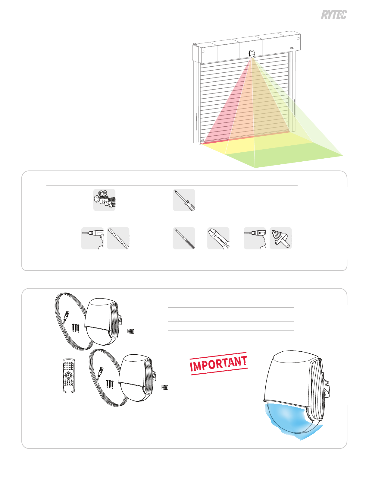
How to install and set up the widescan laser sensor
NOTICE
Contact Rytec Technical support at 800-628-1909 if you have questions about these instructions.
The meaning of signal words
Summary: Technical content produced by Rytec includes safety information which must be read, understood and obeyed to reduce the risk of death, personal injury or
meaning of the signal words is as follows:
CAUTION
Caution indicates a hazardous situation that, if not avoided, could result in minor or moderate injury.
NOTICE
Notice is used to address practices not related to physical injury but which, if not followed, could result in damage to the door
or other property.
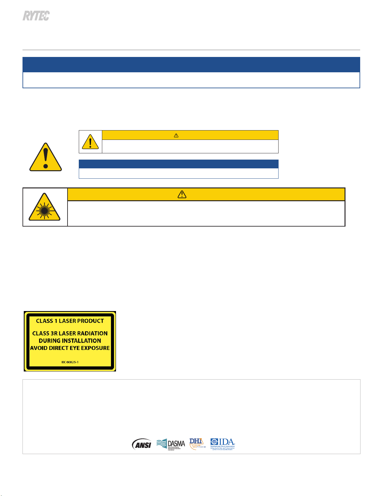
CAUTION
Use of controls, adjustments, or performance of procedures other than those
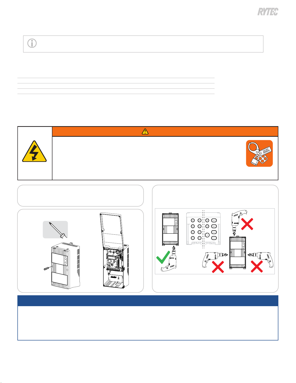
Installation and operation safety
▪Do not look directly into the laser emitter or the visible red laser beams.
▪
▪
▪Following installation,always test for proper operation before leaving the premises.
▪
The device contains IR and visible laser diodes.
IR laser: wavelength 905nm; max. output pulse power 75W
(Class 1 according to IEC 60825-1)
Visible laser: wavelength 650nm; max. output CW power 3mW
(Class 3R according to IEC 60825-1)
The visible laser beams are inactive during normal functioning.
The installer can activate the visible lasers if needed.
BEA, INC. INSTALLATION/SERVICE COMPLIANCE EXPECTATIONS
• BEA, Inc., the sensor manufacturer, cannot be held responsible for incorrect installations or inappropriate adjustments of the sensor/device; therefore,
• BEA, Inc. does not guarantee any use of the sensor outside of its intended purpose.
•
• Installers and service personnel are responsible for executing a risk assessment following each installation/service performed, ensuring that the sensor system
installation is compliant with local, national, and international regulations, codes, and standards.
• Once installation or service work is complete, a safety inspection of the door/gate shall be performed per the door/gate manufacturer recommendations and/or
per ANSI/DASMA guidelines (where applicable) for best industry practices. Safety inspections must be performed during each service call – examples of these safety
inspections can be found on a safety information label (e.g. ANSI/DASMA 102, ANSI/DASMA 107). Verify that all appropriate industry signage and warning labels and
placards are in place.
BEA Widescan accessory guide