RZB Lighting smart+free 982767.002 User manual

INSTRUCTION
982767.002
General Safety Information
- Electric connection must be appropriate
according to all applicable standards and
other national and international safety and
accident prevention regulations.
- Damaged luminaires must not be
operated.
- No liability is accepted for damages resulting
from improper use.
- Use genuine parts only for repair.
- Ensure stability of the ceiling and fastening
elements.
Operation of the luminaire
- Exceeding the permissible ambient
temperature will reduce the luminaire’s
lifecycle, resulting in premature failure in
extreme cases.
- Avoid ESD problems by not routing feed-
through wiring directly along the wiring of the
luminaire.
- Connect control inputs of dimmable
luminaires with standard cables suitable for
power supply voltage.
Manipulation of our products is not
permitted
Modifications, reworking, re-labelling of
products as well as their package is not
permitted and infringes, amongst others, our
registered trademark rights. Such
modifications may affect technical properties
of our products, damage them and possibly
cause consequential damage to other objects.
The manufacturer shall not be responsible
under any circumstances for damage caused
by such modifications.
Allgemeine Sicherheitshinweise
- Der elektrische Anschluss muss ordnungs-
gemäß nach geltenden Normen und den
nationalen sowie internationalen Sicherheits-
und Unfallverhütungsvorschriften erfolgen.
- Beschädigte Leuchten dürfen nicht betrieben
werden.
- Keine Haftung für Schäden durch unsach-
gemäßen Einsatz.
- Bei Instandsetzung nur Originalteile
verwenden.
- Tragfähigkeit der Decke und Befestigungs-
elemente sicherstellen.
Betrieb der Leuchte
- Die unzulässigen Umgebungstemperaturen
reduzieren die Lebensdauer der Leuchte, im
Extremfall droht der Frühausfall.
- Zur Vermeidung von EMV-Problemen die
Durchgangsverdrahtung nicht entlang der
Leuchtenverdrahtung führen.
- Steuereingänge von dimmbaren Leuchten
mit handelsüblichen für Netzspannung ge-
eigneten Leitungen anschließen.
Manipulationen unserer Produkte sind
unzulässig
Veränderung, Umarbeitung, Umkennzeich-
nung von Produkten sowie deren Verpackung
sind unzulässig und verletzen u.a. unsere
eingetragenen Warenzeichenrechte. Solche
Modifikationen können technische Eigen-
schaften unserer Produkte negativ beeinflus-
sen, diese zerstören und möglicherweise
Folgeschäden an anderen Objekten verursa-
chen. Für durch derartige Modifikationen ver-
ursachte Schäden kann der Hersteller in
keinem Fall verantwortlich gemacht werden.
2 www.rzb.de 2023-03-17

INSTRUCTION
982767.002
Technische Daten:
Netzeingang
Spannungsbereich 220 - 240 V
Frequenz 50 - 60 Hz
Max. Netzstrom 0,35 A
Leerlauf-Standby-Leistung < 0,5 W
Kanal 1 Ausgang
Spannung 0-10 V 0 - 10 VDC, max.7mA
Spannung DALI 12 VDC, max.20 mA
Max.Anzahl angeschlossener Geräte 1 Konverter +
1 Sensor/Taster
Kanal 2 Ausgang
Spannung 0-10 V 0 - 10 VDC, max.7mA
Spannung Relayssteuerung 12 VDC, max.100 mA
Max.Anzahl angeschlossener Geräte 1 Konverter
Funk-Sender/Empfänger
Betriebsfrequenzen: 2,4...2,483 GHz
Max. Ausgangsleistung: + 4 dBm
Betriebsbedingungen
Umgebungstemperatur, Ta -20°C - +45°C
Max. Gehäusetemperatur im Betrieb, Tc +70°C
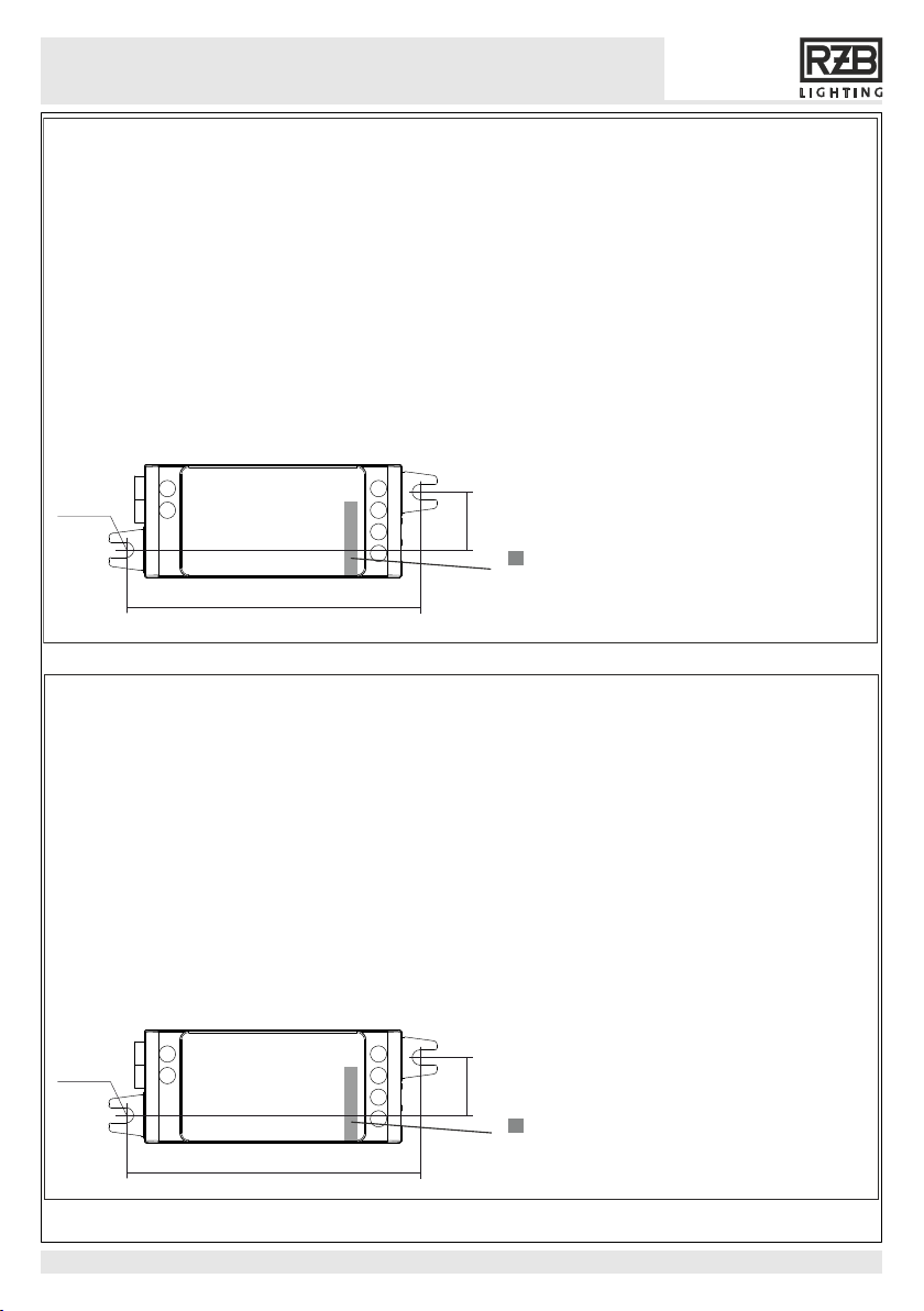
Anschlussleitung
Querschnitt (starr und flexibel) 0,5 - 1,5 mm2
Abisolierlänge: 6 - 7 mm
Anzugsmoment: 0,4 Nm
6 – 7 mm
0,5 – 1,5 mm²
Technical Data:
Mains Input
Voltage range 220 - 240 V
Frequency 50 - 60 Hz
Max. mains current 0,35 A
No-load standby power < 0,5 W
Channel 1 output
Voltage 0-10 V 0 - 10 VDC, max.7mA
Voltage DALI 12 VDC, max.20 mA
Maximum number of drivers 1 driver +
1 sensor/push button
Channel 2 output
Voltage 0-10 V 0 - 10 VDC, max.7mA
Voltage relay control 12 VDC, max.100 mA
Maximum number of drivers 1 driver
Radio transceiver
Operating frequencies: 2,4...2,483 GHz
Maximum output power: + 4 dBm
Operating conditions
Ambient temperature, Ta -20°C - +45°C
Max. case temperature, Tc +70°C
Connectors
Wire cross section range (solid and stranded) 0,5 - 1,5 mm2
Wire strip length: 6 - 7 mm
Tightening torque: 0,4 Nm
6 – 7 mm
0,5 – 1,5 mm²
!Disposal Instructions
In line with EU Directive 2002/96/EC for waste electrical and electronic equipment (WEEE),
this electrical product must not be disposed of as unsorted municipal waste.
Please dispose of this product by returning it to the point of sale or to your local municipal
collection point for recycling.
Entsorgungshinweis
Gemäß EU-Richtlinie 2002/96/ EG für Elektro- und Elektronik-Altgeräte (WEEE), darf dieses
elektrische Produkt nicht mit dem gewöhnlichen unsortierten Hausmüll entsorgt werden.
Bitte entsorgen Sie dieses Produkt, indem Sie es dort zurückgeben, wo Sie es erworben
haben, oder bei einer kommunalen Recycling-Sammelstelle in Ihrer Nähe.
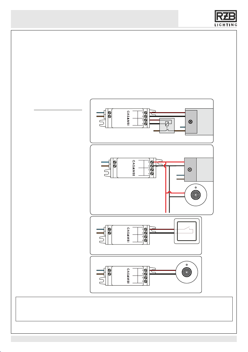
Hinweis 1. Eine eingebaute Steuereinheit ist ein Gerät der Schutzklasse II. Eine externe Installationsbox
( z.B. Abzweigbox 982391.009) verwenden, falls die Steuereinheit nicht in einem anderen isolierten Gerät
Hinweis 2. Die Steuereinheit und die DALI Schnittstelle entsprechen nicht den Anforderungen
von IEC 60929! Nur direkt an einen DALI-dimmbaren LED Treiber anschließen. Nicht an ein bestehendes
DALI Netzwerk anschließen.
!
Note 1. The control unit is a built-in class II device. Use an external mounting box
(e.g. junction box 982391.009), if the control unit is not mounted inside another insulated device.
Note 2. Control unit and its DALI interface do not comply with IEC 60929!
Connect only directly to a DALI driver. Do not connect to an existing DALI network.
!
eingebaut wird.
+ - + -
1-10V 1-10V
DALI RELAY
CH1 CH2
N L
4 www.rzb.de 2023-03-17

INSTRUCTION
982767.002
Description
Beschreibung
Der CBU-A2D ist ein Bluetooth steuerbarer, Casambi-fähiger 2-Kanal 0-10V/DALI-Controller.
Das Produkt kann in einen Dali-Modus konfiguriert werden, in dem es an einen Dali-LED-Treiber oder
Dali-Sensor für Präsenz- und/oder Tageslichtnutzungsfunktionen angeschlossen werden kann.
Das Modul wird über einen universellen Eingangsspannungsbereich von 100-277 VAC betrieben.
CBU-A2D kann auch einen oder zwei steuerbare 0-10-V-LED-Treiber oder einen Tunable White
LED-Treiber mit zwei 0-10-V-Steuerschnittstellen ansteuern.
CBU-A2D wird drahtlos per Bluetooth von der CASAMBI Smartphone und Tablet App gesteuert.
Die CASAMBI-App kann kostenlos aus dem Apple App Store und dem Google Play Store
heruntergeladen werden.
Verschiedene Casambi-fähige Produkte können von einer einfachen Direktansteuerung einer Leuchte
bis hin zu einem kompletten und vollwertigen Lichtsteuersystemen eingesetzt werden, bei dem bis zu
250 Einheiten automatisch ein intelligentes Mesh-Netzwerk bilden.
CBU-A2D is a Bluetooth controllable, Casambi enabled 2 channel 0-10V/ DALI controller.
The module has a universal 100-277 VAC input voltage range.
CBU-A2D can also control one or two 0-10V controllable LED drivers, or it can control a tunable white
LED driver with two 0-10V control interfaces.
The product can be configured into a DALI mode where it can be connected to a DALI LED driver or
DALI sensor for presence and/or daylight harvesting functions.
CBU-A2D can be controlled with Casambi app which can be downloaded free of charge from
Apple App Store and Google Play Store.
Different Casambi enabled products can be used from a simple one luminaire direct control to a complete
and full featured light control system where up to 250 units form automatically an intelligent mesh network.
2023-03-17 www.rzb.de 5

INSTRUCTION
982767.002
Stellen Sie sicher, dass der Strom ausgeschaltet ist, bevor die Klemmen verdrahtet werden.
2
Nur 0,5-1,5 mm massive oder flexible Leitungen verwenden. Am Ende der Leitung ca 6-7mm
der Ummantelung abisolieren. Bei Benutzung flexibler Leitungen müssen Aderendhülsen
Kabel in die entsprechenden Anschlüsse einführen und die Anschlussschrauben festziehen.
Stellen Sie sicher, dass Eingang und Ausgang richtig angeschlossen sind.
Der Netzeingang ist mit den Buchstaben L und N markiert.
Der DALI-Ausgang ist mit einem + und – Zeichen markiert.
Wird die Steuereinheit in einer warmen Umgebung installiert (z.B. in einer Leuchte oder in einem
Deckenauslass über einer Leuchte) muss beachtet werden, dass die Umgebungstemperatur
nicht den angegebenen maximalen Wert überschreitet.
verwendet werden.
Installation
!Warnung!
Schließen Sie die Ausgangskanäle nicht parallel an. Dies kann das Produkt dauerhaft beschädigen.
Anschluss-Schemas:
Optional 12V Relay,
nur mit 0/1-10V
ein Treiber und Relay
Steuerleitung
N
0/1-10V oder
DALI Treiber
N
L
L
CBU-A2D
0-10V/
CH1 CH2
LN
max. 12V
20 mA
max. 12V
100 mA
DALI
0-10V/
RELAY
2ch 0-10V/
DALI controller
INPUT: 100-240 VAC
35 mA
0-10V
ein DALI Treiber und Sensor
0-10V driver 1
0-10V
CBU-A2D
0-10V/
CH1 CH2
LN
max. 12V
20 mA
max. 12V
100 mA
DALI
0-10V/
RELAY
2ch 0-10V/
DALI controller
INPUT: 100-240 VAC
35 mA
N
L
Steuerleitung
DALI Treiber
N
L
Passiver DALI
Sensor
Taster
Elektronischer
Taster
CBU-A2D
0-10V/
CH1 CH2
LN
max. 12V
20 mA
max. 12V
100 mA
DALI
0-10V/
RELAY
2ch 0-10V/
DALI controller
INPUT: 100-240 VAC
35 mA
N
L
DALI Sensor
Passiver DALI
Sensor
CBU-A2D
0-10V/
CH1 CH2
LN
max. 12V
20 mA
max. 12V
100 mA
DALI
0-10V/
RELAY
2ch 0-10V/
DALI controller
INPUT: 100-240 VAC
35 mA
N
L
6 www.rzb.de 2023-03-17

INSTRUCTION
982767.002
Make sure that the mains voltage is switched off when making any connections.
2
Use 0.5 - 1.5 mm solid or stranded conductor electrical wires.
Strip the wire 6-7 mm from the end. When using flexible cables, ferrules must be used.
Insert the wires to the corresponding holes and tighten the connector screw.
Make sure to connect the input and outputs correctly.
The DALI output is marked with + and - symbols.
If you install the control unit in a warm environment (i.e. inside a luminaire or in a ceiling outlet
box above a luminaire), make sure that the ambient temperature does not exceed the
specified maximum value.
Installation
Mains input connector is marked with letters L and N.
!Warning!
Do not connect the output channels in parallel. This may cause permanent damage to the product.
Wiring-diagrams:
Optional 12V relay,
only with 0/1-10V
one driver and relay
Control wires
N
0/1-10V or
DALI driver
N
L
L
CBU-A2D
0-10V/
CH1 CH2
LN
max. 12V
20 mA
max. 12V
100 mA
DALI
0-10V/
RELAY
2ch 0-10V/
DALI controller
INPUT: 100-240 VAC
35 mA
0-10V
one DALI driver and sensor
0-10V driver 1
0-10V
CBU-A2D
0-10V/
CH1 CH2
LN
max. 12V
20 mA
max. 12V
100 mA
DALI
0-10V/
RELAY
2ch 0-10V/
DALI controller
INPUT: 100-240 VAC
35 mA
N
L
Control wires
DALI driver
N
L
Passive DALI
sensor
Push Button
Momentary
push button
CBU-A2D
0-10V/
CH1 CH2
LN
max. 12V
20 mA
max. 12V
100 mA
DALI
0-10V/
RELAY
2ch 0-10V/
DALI controller
INPUT: 100-240 VAC
35 mA
N
L
DALI sensor
Passive DALI
sensor
CBU-A2D
0-10V/
CH1 CH2
LN
max. 12V
20 mA
max. 12V
100 mA
DALI
0-10V/
RELAY
2ch 0-10V/
DALI controller
INPUT: 100-240 VAC
35 mA
N
L
2023-03-17 www.rzb.de 7

INSTRUCTION
982767.002
The control unit has an integrated antenna for easy application.
To optimize the coverage in each direction, some design guidelines should be followed
when installing the device.
The antenna is located at the corner of the housing.It is located at the bottom of the printed
circuit board, directly above the bottom of the device.
The control unit has some large components on the top of the circuit board.
So if you mount the antenna at the bottom, the other components have the least
possible impact on the antenna performance.
If the device is mounted on a metal plate (for example on the frame of a luminaire),
the radio signal can be permanently disturbed.
In this case, under certain circumstances, a cut below the antenna is required so that
the radio signal can exit the structure.
The cut-out area should be as large as possible.
Also, the device should be placed as far away as possible from vertical metal structures.
!Antenna cut-out area is located
on the bottom of the device.
Die Steuereinheit verfügt über eine integrierte Antenne für eine einfache Integration.
Um die Reichweite in jede Richtung zu optimieren, sollten bei der Montage des Gerätes einige
Designrichtlinien beachtet werden.
Die Antenne befindet sich an der Ecke des Gehäuses. Sie befindet sich an der Unterseite
der Leiterplatte, direkt über dem Boden des Geräts.
Die Steuereinheit verfügt über einige große Komponenten an der Oberseite der Leiterplatte.
Wenn Sie also die Antenne an der Unterseite platzieren, haben die anderen Komponenten
so den geringstmöglichen Einfluss auf die Antennenleistung.
Wird das Gerät an einer Metallplatte montiert (z.B. am Rahmen einer Leuchte), kann dadurch
das Funksignal nachhaltig gestört werden. In diesem Fall ist unter Umständen ein Ausschnitt
unterhalb der Antenne erforderlich, damit das Funksignal die Konstruktion verlassen kann.
Der ausgeschnittene Bereich sollte so groß wie möglich sein.
Auch sollte das Gerät so weit wie möglich entfent von vertikalen Metallstrukturen platziert werden.
Antennenausschnittsfläche
befindet sich auf der Geräteunterseite.
!
Platzierung in einer Leuchte
Placement in a luminaire
13,4
68,0
Ø 3,5
13,4
68,0
Ø 3,5
8 www.rzb.de 2023-03-17

INSTRUCTION
982767.002
Die Reichweite des Funksignals hängt von der Umgebung ab, z.B. Leuchte,
Möbel, Menschen oder der Gebäudekonstruktion. Sie muss in der Installation
geprüft und abgenommen werden.
The range of the radio signal depends on the environment, e.g. on luminaire,
building construction, furniture or people. It must be testes and approved in the
installation.
Um eine gute Funkverbindung zu gewährleisten, darf die Steuereinheit nicht
komplett mit Metall verdeckt werden!
To ensure a good radio connection, the control unit must not be completely
covered with metal!
!
!
Reichweite
Range
Funk-Sender / Empfänger
transmitter / receiver
Betriebsfrequenzen:
Operating Conditions:
Max. Ausgangsleistung:
Max. Output power:
2,4 ... 2,483 GHz
+ 4 dBm
Mit Casambi Mesh Network Technologie agiert jede Steuereinheit auch als ein Repeater.
Durch den Einsatz mehrerer Casambi Units können größere Reichweiten erreicht werden.
Casambi uses mesh network technology so each CBU-ASD acts also as a repeater.
Longer ranges can be achieved by using multiple Casambi units.
Kompatible Geräte:
Comaptible devices:
iPhone 4S oder später
or later
iPod 3 oder später
or later
iPod Touch 5th Gen. oder später
or later
Android 4.4
KitKat
oder später produziert als
or later devices produced
2013 mit kompletter Blue-
tooth 4.0 Unterstützung
support
after 2013 with full BT 4.0
Bis zu 15 m
Up to 15 m
1)
1) 40 m
1)
Die Reichweite ist stark von den umlie-
genden Hindernissen wie Wänden und
den Baumaterialien abhängig.
Range is highly dependant on the
surrounding and obstacles such as walls
and building materials.
1)
2023-03-17 www.rzb.de 9

INSTRUCTION
982767.002
Casambi- App aus dem Apple App Store oder Google Play Store downloaden.
Download the app from Apple App Store or Google Play Store.
1.
Smart + free- Steuereinheit betriebene Leuchte einschalten
Switch on your Casambi enabled luminaires.
2.
App öffnen.
Open the app.
3.
Die App findet automatisch die Leuchten, die eingeschaltet sind
Casambi app will automatically find all Casambi enabled luminares that are switched on.
4.
Klicken Sie auf „Alle Leuchten in Benutzung nehmen“.
Click on „Take all lamps into use“.
5.
Die Leuchten werden automatisch zu einem Netzwerk hinzugefügt.
Casambi app will automatically add all found luminares to one network and open the
„Lamps“ tab.
6.
Vergeben Sie eine von vier Freigabeoptionen für ihr Netzwerk (siehe Seite „Netzwerke
und Freigabe“)
Assign one of four sharing options for your network (see page „Network setup and
sharing“).
7.
Erstmalige Anwendung
First time use
Casambi app is easy to use. Follow these simple steps:
Die Casambi App ist leicht zu installieren. Folgen Sie einfach diesen Schritten:
Zusatzinfo
Additional info
Link zum iOS
Link to iOS
Link zum Android
Link to Android
Link zur weiteren
Information
Link to more
information
10 www.rzb.de 2023-03-17

INSTRUCTION
982767.002
EU-Konformitätserklärung / EU Declaration of Conformity
www.casambi.com
tel. +358 10 501 2950
Casambi Technologies Oy
Bertel Jungin aukio 1 E
02600 Espoo, Finland
EC Declaration of Conformity
We, the manufacturer
Name:
Casambi Technologies Oy
Address: Bertel Jungin aukio 1 E
02600 Espoo, Finland
Telephone: +358 10 501 2950
declare under our sole responsibility that the following product
Brand name: Casambi
Model: CBU-A2D
Description: Bluetooth 4.0 2ch 0-10V controller
is in conformity with the provisions of Council Directives
Radio Equipment Directive 2014/53/EU
Restriction of Hazardous Substances (RoHS) 2011/65/EC and
Regulation (EC) No 1907/2006 of the European Parliament and of the Council (REACH).
The following harmonised standards and technical specifications have been applied:
Health and Safety (Article 3.1a): IEC 61347-2-11:2001, AMD1:2017
IEC 61347-1:2015, AMD1:2017
Electromagnetic Compatibility (Article 3.1b): ETSI EN 301 489-1 v2.1.1
ETSI EN 301 489-17 v3.1.1
Radio Spectrum Efficiency (Article 3.2): ETSI EN 300 328 v.2.1.1
The last two digits of the year in which the CE marking was affixed: 19
To meet the requirements of these directives the device must be used in accordance with the manu-
facturer’s instructions.
Espoo, 30th of September, 2019
Casambi Technologies Oy
Kai Tötterman,
Director of Harware Design
2023-03-17 www.rzb.de 11
Table of contents
Popular Control Unit manuals by other brands

ARI
ARI Eliptix W-31 Series Installation, Operating, Maintenance

Dejero
Dejero EM9191 Hardware integration guide

Spirax Sarco
Spirax Sarco DN15 Installation and maintenance instructions

pizzato
pizzato CS MF2020-P Series operating instructions

SI
SI JANUS installation instructions

Emerson
Emerson Raimondi HPA 150 Installation & maintenance instructions