manuals.online logo
Brands
  1. Home
  2. •
  3. Brands
  4. •
  5. Siemens
  6. •
  7. Control Unit
  8. •
  9. Siemens 3WN 6 3WX3661-0JA00 User manual

Siemens 3WN 6 3WX3661-0JA00 User manual

1
3WN 6
Betriebsanleitung/Operating Instructions Bestell-Nr./Order No.: 3ZX1812-0WX36-3DA0 / 9239 9809 422
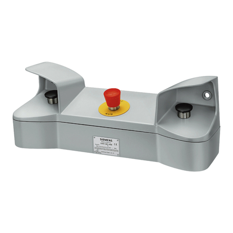
Pilzdrucktaster für Not-Aus 3WX3661-0JA00
Mushroom-head pushbutton for Emergency Stop
Coup-de-poing d’arrêt d’urgence
Pulsador fungiforme para DES de emergencia
Pulsante a fungo per arresto di emergenza
Svampformad tryckknapp för nödstopp
1
1 Pilzdrucktaster für "Not-Aus"
1 Mushroom-head pushbutton for Emergency Stop
1 Coup-de-poing d’arrêt d’urgence
1 Pulsador fungiforme para DES de emergencia
1 Pulsante a fungo per arresto di emergenza
1 Svampformad tryckknapp för „Nödstopp“
Alle Rechte vorbehalten. All rights reserved. Tous droits réservés. Reservados todos los derechos.
Tutti i diretti riservati. All rätt forbehålles.
© Siemens AG 1998
Packungsinhalt überprüfen / Check contents of pack / Vérifier le contenu de l’emballage /
Comprobar el contenido del paquete / Controllare il contenuto dell’imballo / Kontrollera förpackningens innehåll
2
Gefahr!
Gefährliche Spannung!
Gefährlicher Federspeicher!
Vor Beginn der Arbeiten Gerät spannungsfrei schalten
und gegen Wiedereinschalten sichern.
Nur bei ausgeschaltetem Schalter und entspanntem
Federspeicher arbeiten.
Bei Nichtbeachtung können Tod,schwereKörperver-
letzungodererheblicher Sachschadendie Folge sein.
Einbau und Montage nur durch Fachpersonal!
Hazardous voltage!
Hazardous spring pressure!
Before beginning work on the unit, switch it to a de-
energized state and secure it against reactivation.
Work only with the circuit-breaker switched off and the
spring discharged.
Non-observance can result in death, severe personal
injury or substantial property damage.
Only qualified personnel may perform installation and
assembly work.
Danger!
Attention!
Tension électrique dangereuse!
Tension de ressort dangereuse!
Avant le début des travaux, mettre l'appareil hors
tension et le consigner dans cette position.
Intervenir uniquement sur l’appareil en position
d’ouverture et lorsque le ressort d’accumulation
d’énergie est détendu.
Le non-respect de ces mesures de sécurité peut
entraîner la mort, des blessures graves ou des
dommagesmatérielsimportants.Installationetmontage
uniquement par des personnes qualifiées.
¡Tensión peligrosa!
¡Resorte peligroso!
Antes de iniciar los trabajos hay que desconectar el
aparato y asegurarlo contra reconexiones.
Trabajarúnicamenteconelinterruptordesconectadoy
el resorte destensado.
La inobservancia de esta advertencia puede causar la
muerte, graves lesiones corporales o altos daños ma-
teriales.
¡Montaje sólo por personal experto!
¡Peligro!
Attenzione!
Tensione elettrica pericolosa!
Molle precariche!
Prima di iniziare i lavori, assicurarsi che l’apparecchio
non sia in tensione e che non sia possibile una
reinserzioneaccidentale.Lavoraresoltantoainterruttore
disinserito e a molle scariche. La mancata osservanza
di tali norme può provocare incidenti mortali, gravi
lesioni alle persone e ingenti danni materiali.
L’installazione e il montaggio devono essere effettuati
esclusivamente da personale specializzato!
Farlig spänning!
Farlig fjäderspänning!
Innan arbetena påbörjas skall apparaten kopplas
spänningsfri och säkras mot återinkoppling.
Arbeta endast vid frånkopplad brytare och avspänd
fjäder.
Omdettainteiakttaskandöd,svårakroppsskadoreller
betydande materielskador vara följden.
Installering och montering endast av fackpersonal!
Varning!
Deutsch
Italiano
Français
English
Svenska
Español
3
Bedienpult abnehmen / Remove the control panel / Dépose du panneau de commande /
Desmontar el panel de control / Asportare il pannello frontale di comando / Montera av manövertavlan
Achtung! Bei Einschubschaltern: Erst Kurbelloch schließen, dann Bedienpult
abnehmen! /
Caution! With draw-out circuit-breakers, close off the crank hole before lifting off
the control panel. /
Attention! Sur les disjoncteurs débrochables: fermer l’ouverture pour manivelle
avant de déposer le panneau de commande! /
¡Atención! En interruptores extraíbles, cerrar primero la abertura de la manivela y
desmontar el panel de control después. /
Attenzione! Congliinterruttoriinesecuzioneestraibile:chiudereilforodellamanovella
prima di asportare il pannello frontale di comando./
Viktigt! Vidutdragbarabrytare: Stängförstvevhålet,tasedanavmanövertavlan!
2.1
- Befestigungsschrauben (2.1) lösen
Werkzeug: Kreuzschlitzschraubendreher Größe 2
- Handhebel (2.2) nach vorn schwenken
- Bedienpult (2) nach vorn abziehen
- Desserrer les vis de fixation (2.1).
Outil: tournevis cruciforme taille 2.
- Rabattre le levier (2.2) vers l’avant.
- Déposer le panneau de commande (2) en le tirant
vers l’avant
- Allentare la vite di fissaggio (2.1)
Attrezzo: cacciavite a croce grandezza 2
- Abbassare la leva di comando (2.2) tirandola in
avanti
- Asportareilpannellofrontaledicomando(2)tirandolo
in avanti
2.2 2
- Undo fixing screws (2.1)
Tool: Phillips screwdriver size 2
- Swing hand lever (2.2) forwards
- Extract the contol panel (2) towards you
- Soltar los tornillos de fijación (2.1)
Herramienta: Destornillador de estrella tamaño 2
- Abatir la palanca manual (2.2) hacia delante
- Extraer el panel de control (2) hacia delante
- Lossa fästskruvarna (2.1)
Verktyg: kryss-spårmejsel storlek 2
- Sväng handspaken (2.2) framåt
- Dra av manövertavlan (2) framåt
Deutsch
English
Italiano Français
Español
Svenska
4
2
4
- Bedienpult (2) aufrecht hinstellen. Unterlage für
Höhenausgleich verwenden
- Gewindestifte (3) lösen
- MechanischenAus-Taster (4)wie dargestelltgegen
Druckplatte (5) verdrehen
- Mechanischen Aus-Taster (4) aus Bedienpult (2)
herausziehen
Hinweis: Druckplatte (5) wird wiederverwendet.
- Poserlepanneaudecommande(2)àlaverticale.Le
caler en conséquence
- Défaire les vis sans tête (3)
- Tourner le bouton d’ARRET mécanique par rapport
à la plaque (5) comme représenté sur la figure
- Dégagerle boutond’ARRETmécanique (4)du pan-
neau de commande (2)
Remarque : réutiliser la plaque (5).
- Collocare il pannello frontale di comando (2) in
posizioneverticale. Servirsidiuna basedi appoggio
per compensare eventuali disivelli
- Svitare i perni (3)
- Farruotare il pulsante(4) erimuverlodalla piastradi
tenuta (5)
- EstrarreilpulsantediOFFmeccanico(4)dalpannel-
lo frontale di comando
Avvertenza: la piastra di tenuta (5) viene riutilizzata.
3
4
3
5
Mechanischen Aus-Taster ausbauen / Remove mechanical OFF button /
Démonter le bouton d’ARRET mécanique / Desmontar el pulsador DES mecánico /
Smontare il pulsante di ”OFF meccanico” / Urmontering av knappen för mekaniskt från
- Place control panel (2) upright on a suitable surface
to allow for differences in height
- Undo threaded pins (3)
- Turn mechanical OFF button (4) as shown in
opposition to thrust plate (5)
- Remove mechanical OFF button (4) from control
panel (2)
Note: Plate (5) is re-used.
- Colocar el panel de control (2) en posición vertical.
Utilizar una base para compensar alturas
- Soltar los tornillos prisioneros (3)
- Girar el pulsador DES mecánico (4) contra la placa
de presión (5) tal como se indica
- ExtraerloelpulsadorDESmecánico (4)delpanelde
control (2)
Nota: La placa de presión (5) se vuelve a utilizar.
- Ställmanövertavlan(2)upprätt.Användunderlagför
höjdutjämning.
- Lossa de gängade stiften (3).
- Vrid knappen för mekaniskt från (4) mot tryckplattan
(5) enligt bilden.
- Dra ut knappen för mekaniskt från (4) ur manöver-
tavlan (2).
Observera: Tryckplattan (5) återanvänds.
Deutsch
Italiano
English
Français
Español
Svenska
5
Not-Aus-Tastereinbauen / FitEmergency Stop /Montage du coup-de-poing d’arrêt d’urgence / Montarel pulsador DES
de emergencia / Montare il pulsante a fungo per arresto di emergenza / Inmontering av nödstoppsknappen
3
5
3
1
- Not-Aus-Taster (1) in Bedienpult (2) stecken
- Not-Aus-Taster (1) wie dargestellt gegen Druckplat-
te (5) verdrehen
- Gewindestifte (3) festschrauben
Dabeiistdaraufzuachten,daßdieGewindestifte(3)
auf den dafür vorgesehenen Markierungen am
Bedienpult (2) aufliegen
- Engagerlecoup-de-poingd’arrêtd’urgence(1)dans
le panneau de commande (2)
- Tourner le coup-de-poing d’arrêt d’urgence (1) par
rapport à la plaque (5) comme représenté sur la
figure
- Serrer les vis sans tête (3)
Veiller à ce que les vis sans tête (3) prennent appui
surles repèresprévussur lepanneau decommande (2)
- Introdurre il pulsante di emergenza (1) nel pannello
frontale di comando (2)
- Ruotare il pulsante di emergenza (1) esercitando
una leggera pressione contro la piastra di tenuta (5)
procedendo come illustarto in figura
- Serrare i perni filettati (3)
Verificare che i perni filettati (3) si trovino sui
contrassegni predisposti sul pannello frontale (2)
- InsertEmergencyStopbutton(1)incontrolpanel(2)
- Turn Emergency Stop (1) as shown in opposition to
thrust plate (5)
- Tighten threaded pins (3). Ensure that the threaded
pins(3) areup against themarkings providedon the
control panel (2)
- Introducir el pulsador DES de emergencia (1) en el
panel de control (2)
- Girar el pulsador DES de emergencia (1) contra la
placa de presión (5)
- Apretar los tornillos prisioneros (3)
Cuidar de que los tornillos prisioneros (3) estén
alineados con las marcas del panel de control (2)
- Stick in nödstoppsknappen (1) i manövertavlan.
- Vridnödstoppsknappen(1)mottryckplattan(5)enligt
bilden
- Skruva fast de gängade stiften (3)
Därvid skall ges akt på att de gängade stiften (3)
ligger mot de därför avsedda markeringarna på
manövertavlan (2)
Deutsch
English
Italiano Français
Español
Svenska
6
Abschließende Arbeiten / Final operations / Travaux définitifs /
Trabajos finales / Operazione conclusive / Avslutande arbeten
Bedienpult in umgekehrter Reihenfolge anbauen /
Fit the control panel in reverse order /
Remonter le panneau de commande dans l’ordre inverse des opérations de démontage. /
Montar el panel de control en orden inverso /
Montare il pannello frontale di comando procedendo nell’ordine inverso /
Montera fast manövertavlan i omvänd ordningsföljd.
Achtung! Bei Einschubschaltern: Erst Kurbelloch schließen, dann Be-dienpult aufsetzen!
Caution! With draw-out circuit-breakers, close off the crank before fitting control panel!
Attention! Surlesdisjoncteursdébrochables:fermerl’ouverturepourmanivelleavantderemonterlepanneaudecommande!
¡Atención! En interruptores extraíbles, cerrar primero la abertura de la manivela y montar el panel de control después.
Attenzione! Con interruttori in esecuzione estraibile: chiudere il foro della manovella di comando, prima di montare il pannello
frontale di comando!
Viktigt! Vid utdragbara brytare: Stäng först vevhålet och sätt sedan på manövertavlan!
5 ± 0,5 Nm
2.2
2.1
7
Z = S 12
IEC 947-2
EN 60 947-2
DIN VDE 0660 T. 101
Cat. B
U
imp = 8 kV .....
.....
a.c.
d.c.
a.c.
d.c.
V
V
V
V
.....
.....
-
-
.....
..... .....
.....
-
-
M
... ... ...
Y1
V
V
V
V
V
V
F1
F2 .....
.....
a.c.
d.c.
a.c.
d.c. .....
.....
.....
..... .....
.....
.....
.....
a.c.
d.c. .....
.....
-
-
-
-
-
-
....
U <
.......
Ident.-Nr. ...............
1
2
1
2
1
2
..... A
3WN6 ... - ..... - .... Z =
3WN6
d.c.
a.c. 415 V
400 V
Leistungsschild aktualisieren (nur nach Nachrüstung) / Updating the rating plate (only after retrofitting) /
Actualisationdelaplaquesignalétique(uniquementaprèséquipement)/Actualizarlaplacadecaracterísticas(sólotras
equipamiento posterior) / Aggiornare la targhetta dati dell’interruttore automatico (solo in caso di montaggio
successivo) / Aktualisera brytarens märkskylt (endast efter komplettering i efterhand)
Das Leistungsschild entsprechend Abbildung mit wisch- und wasserfestem Stift ändern. /
Using an indelible ink pen, alter the rating plate as shown in the figure. /
Modifier les indications de la plaque signalètique d'après la figure et le tableau; utiliser un feutre indélébile. /
Modificar la placa de características según la figura con rotulador permanente. /
Modificare i dati di targa con un pennarello indelebile come indicato nell'immagine. /
Ändra märkskylten enligt figur med gnugg- och vattenfast penna.
Ein neues Leistungsschild ist unter Angabe der kompletten Schalterbestellnummer im Schaltwerk bestellbar.
Bestellnummer für das Leistungsschild: 3T 250 01705 001 /
A new rating plate can be ordered from the works by specifying the complete circuit-breaker order number.
Order number for the rating plate: 3T 250 01705 001 /
Une nouvelle plaque signalétique peut être commandée à l'usine. Indiquer le numéro de référence complet du disjoncteur.
N° de réf. pour plaque signalètique: 3T 250 01705 001 /
Puede solicitarse una placa de características nueva en fábrica indicando el número completo de pedido del interruptor.
Número de pedido de la placa: 3T 250 01705 001 /
Una nuova targa può essere richiesta alla fabbrica indicando il numero di ordinazione completo dell'interruttore.
Numero di ordinazione della targa: 3T 250 01705 001 /
En ny märkskylt kan beställas från firman under angivande av det kompletta numret för brytaren.
Beställningsnummer för märkskylten: 3T 250 01705 001.
8
Bestell-Nr./Order No.: 3ZX1812-0WX36-3DA0 / 9239 9809 422
Bestell-Ort/Place of order: A&D CD SE LK2 Berlin
Printed in the Federal Republic of Germany
AG 03.99 Kb De-En-Fr-Sp-It-Sv
Siemens Aktiengesellschaft
Herausgegeben von
Bereich Automatisierungs- und Antriebstechnik
Niederspannungs-Schalttechnik
Schaltwerk Berlin
D - 13623 Berlin
Änderungen vorbehalten
Published by the
Automation & Drives Group
Control and Distribution
Schaltwerk Berlin
D - 13623 Berlin
Federal Republic of Germany
Subject to change

Other Siemens Control Unit manuals

Siemens SINAMICS V60 User manual

Siemens

Siemens SINAMICS V60 User manual

Siemens 3RK1200-0C.03-0AA2 User manual

Siemens

Siemens 3RK1200-0C.03-0AA2 User manual

Siemens Simatic S7-1500 User manual

Siemens

Siemens Simatic S7-1500 User manual

Siemens SIRIUS 3RV2.2 User manual

Siemens

Siemens SIRIUS 3RV2.2 User manual

Siemens SIMATIC NET CP 1243-1 DNP3 Instruction sheet

Siemens

Siemens SIMATIC NET CP 1243-1 DNP3 Instruction sheet

Siemens 3RK1408-8K.00-0AA2 User manual

Siemens

Siemens 3RK1408-8K.00-0AA2 User manual

Siemens FS-TRI-M User manual

Siemens

Siemens FS-TRI-M User manual

Siemens SINAMICS S120 Technical Document

Siemens

Siemens SINAMICS S120 Technical Document

Siemens SINUMERIK 840D sl Owner's manual

Siemens

Siemens SINUMERIK 840D sl Owner's manual

Siemens SIMATIC ET 200SP User manual

Siemens

Siemens SIMATIC ET 200SP User manual

Siemens Synco RMZ792 Operator's manual

Siemens

Siemens Synco RMZ792 Operator's manual

Siemens SIRIUS ACT 3SU1400-1EK10-6AA0 User manual

Siemens

Siemens SIRIUS ACT 3SU1400-1EK10-6AA0 User manual

Siemens SINAMICS G120P CU230P-2 Administrator guide

Siemens

Siemens SINAMICS G120P CU230P-2 Administrator guide

Siemens SIMOTION D425 User manual

Siemens

Siemens SIMOTION D425 User manual

Siemens Simatic S7-1500/ET 200MP Technical Document

Siemens

Siemens Simatic S7-1500/ET 200MP Technical Document

Siemens SINAMICS G120 User manual

Siemens

Siemens SINAMICS G120 User manual

Siemens SINAMICS S120 Technical Document

Siemens

Siemens SINAMICS S120 Technical Document

Siemens LEC1 Series User manual

Siemens

Siemens LEC1 Series User manual

Siemens 2AI 2/4WIRE HF User manual

Siemens

Siemens 2AI 2/4WIRE HF User manual

Siemens SED2-LONI/F User manual

Siemens

Siemens SED2-LONI/F User manual

Siemens SIWAREX MS Application guide

Siemens

Siemens SIWAREX MS Application guide

Siemens SIMATIC ET 200SP User manual

Siemens

Siemens SIMATIC ET 200SP User manual
Siemens SIMATIC FM 351 User manual

Siemens

Siemens SIMATIC FM 351 User manual

Siemens ALD-2I User manual

Siemens

Siemens ALD-2I User manual

Popular Control Unit manuals by other brands

Hansen HCK4-2 Specifications, Applications, Service Instructions & Parts

Hansen

Hansen HCK4-2 Specifications, Applications, Service Instructions & Parts

WURM EEV module Product information

WURM

WURM EEV module Product information

C&T Solution MX100 Series user manual

C&T Solution

C&T Solution MX100 Series user manual

ALGE-Timing SU3 manual

ALGE-Timing

ALGE-Timing SU3 manual

Fisher-Rosemount Posi-Seal A31 instruction manual

Fisher-Rosemount

Fisher-Rosemount Posi-Seal A31 instruction manual

Arduino NRF24L01 Tutorial

Arduino

Arduino NRF24L01 Tutorial

WAGO 753-646 manual

WAGO

WAGO 753-646 manual

Samson BR14b operating instructions

Samson

Samson BR14b operating instructions

Omron CS1W-LC001 Operation manual

Omron

Omron CS1W-LC001 Operation manual

Tyco DV-5 quick start guide

Tyco

Tyco DV-5 quick start guide

VPC D1 user manual

VPC

VPC D1 user manual

Alpha Group Out Back Power MATE3s Programming guide

Alpha Group

Alpha Group Out Back Power MATE3s Programming guide

Festo VSNZ-FT-T32C-M-F-P1-T Series Assembly instructions

Festo

Festo VSNZ-FT-T32C-M-F-P1-T Series Assembly instructions

HP E3456A user guide

HP

HP E3456A user guide

DSC PowerSeries Neo V1.2 installation guide

DSC

DSC PowerSeries Neo V1.2 installation guide

Enclustra Mercury XU5 user manual

Enclustra

Enclustra Mercury XU5 user manual

Harvia C260 manual

Harvia

Harvia C260 manual

Fisher EMERSON DVC6200 Mounting instructions

Fisher

Fisher EMERSON DVC6200 Mounting instructions

manuals.online logo
manuals.online logoBrands
  • About & Mission
  • Contact us
  • Privacy Policy
  • Terms and Conditions

Copyright 2025 Manuals.Online. All Rights Reserved.