Samsomatic 3962-9 Service manual

Series 3962
Ex d Solenoid Valve
Type 3962-9
Fig. 1 · Type 3962-9
Mounting and
Operating Instructions
EB 3962-1 EN
Edition November 2009

Contents
Contents Page
1 Mounting............................................................................................................4
1.1 Wall mounting....................................................................................................4
1.2 Mounting on rotary actuators with NAMUR interface acc. to VDI/VDE 3845...........4
1.3 Mounting on linear actuators with NAMUR rib acc. to IEC 60534-6-1 using
adapter plates.....................................................................................................5
1.4 Mounting on linear actuators using CrNiMo pipe fittings........................................5
2 Pneumatic connections........................................................................................6
2.1 General..............................................................................................................6
2.2 Connecting line...................................................................................................6
2.3 Operating medium for the booster valve................................................................6
2.4 Auxiliary air for the pilot valve.............................................................................6
2.5 Converting to external auxiliary air routing through connection 9............................7
2.5.1 Type 3962-9XXX14.............................................................................................7
2.5.2 Type 3962-9XXX13.............................................................................................7
3 Electrical connections..........................................................................................9
3.1 Cable entries.......................................................................................................9
4 Certificates.......................................................................................................12
2EB 3962-1 EN

Safety instructions
EB 3962-1 EN 3
General safety instructions
➢The solenoid valves are to be assembled, started up or operated only by trained
and experienced personnel familiar with the product.
According to these mounting and operating instructions, trained personnel is
referred to as individuals who are able to judge the work they are assigned
to and recognize possible dangers due to their specialized training, their
knowledge and experience as well as their knowledge of the applicable
standards.
➢Proper shipping and storage are assumed.
➢Explosion-protected solenoid valve versions are to be operated only by per-
sonnel who has undergone special training or instructions or who is author-
ized to work on explosion-protected devices in hazardous areas.
For technical data, order specifications, spare parts and accessories refer to
Data Sheet T 3962.
➢Make sure the maximum permissible supply pressure is not exceeded. If neces-
sary, reduce the supply pressure using a suitable supply pressure regulator.
➢The solenoid valves can be installed in any desired position. Make sure the filter
in the lid and the cable entries point vertically down. If this mounting position is
not possible, install the solenoid valves with the filter and cable entries in hori-
zontal position.
Important!
➢For installation and maintenance work on the solenoid valves, make sure the
relevant plant section has been depressurized and, depending on the pro-
cess medium, drained as well. Due to the high surface resistance, avoid
electrostatic charging when mounting or servicing the solenoid valves in
hazardous areas. Do not loosen the enameled screws on the housing.
➢The solenoid valves can be mounted on rotary actuators, linear actuators or
control valves with a NAMUR rib using mounting kits. Observe the associ-
ated mounting instructions.

Mounting
1Mounting
1.1 Wall mounting
Types 3962-9XXX13 and 3962-9XXX14
The solenoid valves can be mounted using
the through holes and screws.
Fig. 2 · Booster valve without solenoid valve head
(dimensions in mm)
1.2 Mounting on rotary actuators
with NAMUR interface acc. to
VDI/VDE 3845
Type 3962-9XXX0
The solenoid valves can be mounted on
rotary actuators with NAMUR interface us-
ing the following adapter plates (Fig. 3):
–1400-9741 for ¼” or
–1400-9743 for ½”.
The adapter plates are not included in the
scope of delivery.
Before mounting, check that the two O-rings
are properly positioned. Use the grub screw
to adjust the direction of action on the con-
necting flange of the rotary actuator. Use
two screws for attachment.
Fig. 3 · ¼” NAMUR interface (dimensions in mm)
4EB 3962-1 EN
Grub screw

Mounting
1.3 Mounting on linear actuators
with NAMUR rib acc. to
IEC 60534-6-1 using adapter
plates
Type 3962-9XX00
The solenoid valves can be mounted on lin-
ear actuators with NAMUR rib using ad-
apter plates (Fig. 4). When additionally
mounting positioners or limit switches on lin-
ear actuators in DN 50, an additional
bracket is required (order no. 0320-1416).
Fig 4 · Adapter plate with NAMUR rib (dimensions in
mm)
1.4 Mounting on linear actuators
using CrNiMo pipe fittings
Types 3962-9XX0130 and 3962-9XX0142
The solenoid valves can be mounted on lin-
ear actuators (e.g. SAMSON Type 3271 or
Type 3277) using CrNiMo pipe fittings
(Fig. 5). For mounting instructions on the
SAMSON actuators, refer to Mounting and
Operating Instructions EB 8310 EN and
EB 8311 EN.
Fig. 5 · Mounting on linear actuators using CrNiMo
pipe fittings
Actuator size Connection Order no.
80/240 cm² G ¼ or G ¼ 1400-6759
350/700 cm² G ⅜or G ¼ 1400-6761
G ⅜or G ½ 1400-6735
1400 cm² G ¾ or G ½ 1400-6736
2100 cm² G 1 or G ½ 1400-6737
2800 cm²
EB 3962-1 EN 5

Pneumatic connections
2 Pneumatic connections
2.1 General
Make sure the connecting lines and screw
fittings are routed and installed properly.
Check them for leaks or damage at regular
intervals and replace or repair them, if ne-
cessary. Before starting any repair work, re-
lieve the pressure from the connecting lines
to be opened.
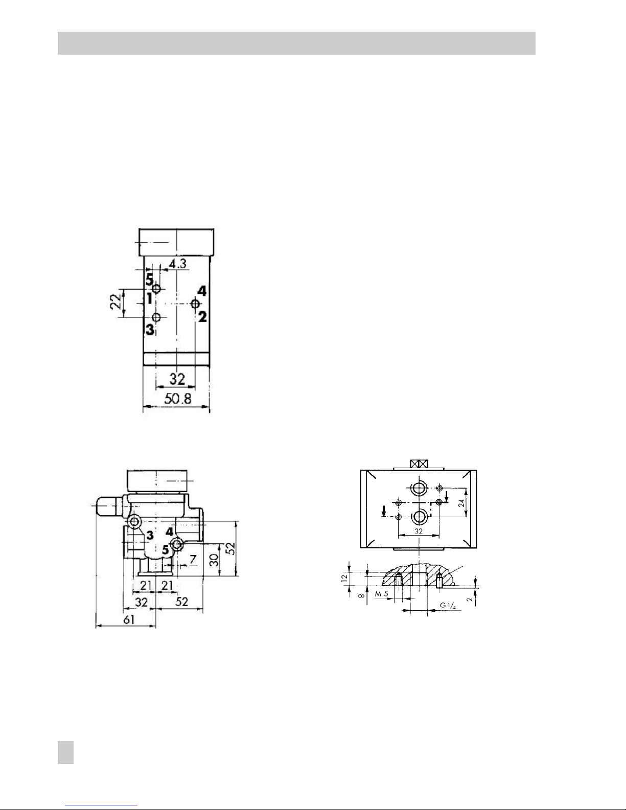
Depending on the solenoid valve version,
the pneumatic connections are established
using either G ¼/¼ NPT or G ½/½ NPT
threaded bores. Install filters or other suit-
able accessories to prevent water or dirt
from getting inside the housing through the
exhaust air connections.
Note! The KVS coefficient of an upstream
supply pressure regulator must be at least
1.6 times higher than the KVS coefficient of
the solenoid valve.
2.2 Connecting line
Refer to the following table for the minimum
required pipe sizes for the connecting lines:
Nominal size (connection length ≤2 m)
KVS 1.4 4.3 –
Connection
Pressure 1 and 3 4 9
≥1.4 bar ≥DN 8 ≥DN 10 ≥DN 4
≥2.5 bar ≥DN 6 ≥DN 8
≥6 bar ≥DN 4 ≥DN 6
Note! Use a larger nominal size for a con-
nection length of more than 2 m.
2.3 Operating medium for the
booster valve
With internal auxiliary air routing:
Instrument air free of corrosive contents or
nitrogen at 1.4 to 8 bar.
With external auxiliary air routing through
connection 9:
Instrument air free of corrosive contents, oil
or non-corrosive gases at 0 to 10 bar with
KVS coefficients between 1.4 and 4.3, supply
air fed through connection 4.
2.4 Auxiliary air for the pilot
valve
Instrument air free of corrosive contents at
1.4 to 8 bar.
Compressed air quality acc. to DIN ISO 8573-1
Particle size
and quantity
Pressure dew point Oil contents
Class 4 Class 3 Class 3
≤5 µm and
1000/m³ –20 °C or at least
10 K below the
lowest ambient
temperature to be
expected
≤1 mg/m³
Note on using nitrogen
If the solenoid valves are mounted in
closed, non-ventilated rooms, make
sure the pilot and booster valves' ex-
haust air is collected in a manifold
line and routed to the atmosphere.
6EB 3962-1 EN

Pneumatic connections
2.5 Converting to external auxili-
ary air routing through con-
nection 9
If the solenoid valve is to be used to switch
the output signal (0 to 8 bar) of a positioner,
route the auxiliary air externally through
connection 9.
2.5.1 Type 3962-9XXX14
If not specified otherwise, the solenoid
valves' auxiliary air is routed internally
through connection 4. To convert to external
routing through connection 9, proceed as
follows (Fig. 6):
1. Remove the cap screw. Remove the
plate (1) and reversible seal (2) from the
connecting plate.
2. Rotate the reversible seal (2) by 90°. Po-
sition the seal such that its tongue rests
in the plate cut-out (9).
3. Fasten the plate (1) and reversible
seal (2) to the connecting plate.
Fig. 6 · Reversible seal, booster valve
2.5.2 Type 3962-9XXX13
Remove the two hexagon socket head
screws (Fig. 7) and the red solenoid valve
head. Make sure the two black O-rings on
the CNOMO interface are not damaged
(Fig. 8).
Fig. 7 · Type 3962-9XXX14 Solenoid Valve
Remove the two hexagon socket head
screws (Fig.8). Carefully remove the
CNOMO interface.
Fig. 8 · CNOMO interface with booster valve
EB 3962-1 EN 7
1 2

Pneumatic connections
Make sure the seals on the booster valve
and the CNOMO interface are not dam-
aged.
Fig. 9 · CNOMO- interface and booster valve
Internal auxiliary air routing:
Make sure the marked hole is not closed by
the black reversible seal (Fig. 10, left).
External auxiliary air routing:
Make sure the marked hole is covered by
the black reversible seal (Fig. 10, right).
Fig. 10 · CNOMO interface; position of reversible seal
for internal (left) and external (right) routing of
the auxiliary air
Carefully place the CNOMO interface onto
the booster valve. Make sure all seals are
properly positioned on the booster valve. If
one seal is missing, replace the entire
Type 3962 Solenoid Valve.
Mounting direction:
Make sure connection 9 of the CNOMO in-
terface (external auxiliary air routing) is loc-
ated on the same side of the booster valve
as connection 1 (supply air) or connection 3
(vent).
Fasten the CNOMO interface using the two
hexagon socket head screws (Fig. 8).
Carefully place the red solenoid valve head
onto the CNOMO interface. Make sure the
two holes in the head are positioned exactly
on the seals of the CNOMO interface. If one
seal is missing, replace the entire Type 3962
Solenoid Valve. Observe the mounting dir-
ection.
Fasten the red solenoid valve head using the
two hexagon socket head screws (Fig. 7).
8EB 3962-1 EN

Electrical connections
3 Electrical connections
Danger!
Electric shocks and/or the formation
of a potentially explosive atmo-
sphere may result in serious injury
or death.
For electrical installation, observe the
relevant electrotechnical regulations and the
accident prevention regulations that apply in
the country of use. In Germany, these are
the VDE regulations and the accident
prevention regulations of the employers’
liability insurance.
The following regulations apply to installa-
tion in hazardous areas:
EN 60079-14:2003; VDE 0165 Part 1:1998
Electrical Apparatus for Explosive Gas
Atmospheres and EN 50281-1-2;
VDE 0165 Part 2:1999 Electrical Apparatus
for Use in the Presence of Combustible Dust.
Install the connecting cable properly so that
it is protected against mechanical damage.
If the temperature at the inlet parts exceeds
70 °C, use a temperature-resistant connect-
ing cable. Include the solenoid valve in the
on-site equipotential bonding system.
Connection in compliance with type of pro-
tection EEx d:
Connect the Type 3962 Solenoid Valve us-
ing suitable cable entries or conduit systems
that comply with EN 60079-1:2004 Explos-
ive Atmospheres – Part 1: Equipment Protec-
tion by Flameproof Enclosures "d",
Clauses 13.1 and 13.2, and for which a
separate test certificate is available.
Do not use cable entries and blanking plugs
of simple construction.
Close unused openings as stipulated in
EN 50018:2000, Clause 11.9.
3.1 Cable entries
Refer to the mounting and maintenance in-
structions for the Ex II 2 GD (EEx d IIC T3-6)
solenoid on pages 10 and 11.
EB 3962-1 EN 9

Electrical connections
10 EB 3962-1 EN

Electrical connections
EB 3962-1 EN 11

Certificates
4Certificates
12 EB 3962-1 EN

Certificates
EB 3962-1 EN 13

Certificates
14 EB 3962-1 EN


EB 3962-1 EN
SAMSOMATIC GmbH
Weismüllerstraße 20-22 · 60314 Frankfurt am Main · Germany
Phone: +49 69 4009-0 · Fax: +49 69 4009-1644
Internet: http://www.samsomatic.de EB 3962-1 ENEB 3962-1 EN
SAMSOMATIC GmbH
Weismüllerstraße 20-22 · 60314 Frankfurt am Main · Germany
Phone: +49 69 4009-0 · Fax: +49 69 4009-1644
Internet: http://www.samsomatic.de
This manual suits for next models
1
Table of contents