S-WORKS Specialized Shiv TT Manual

INSTRUCTION GUIDE
SHIV TT


Page 1 of 20
THIS INSTRUCTION GUIDE CONTAINS IMPORTANT INFORMATION.
PLEASE READ CAREFULLY AND STORE IN A SAFE PLACE.
INTRODUCTION
Congratulations! The Specialized Shiv TT is among the finest advanced composite products available in cycling. Carbon fiber is a very special material
that requires particular care during assembly, storage and riding. This instruction guide contains instructions and warnings, plus torque specifications,
to be used in conjunction with the owner’s manuals and instruction guides supplied with your bicycle.
WARNING! Failure to follow these instructions may result in a catastrophic failure of the frame and/or its components while riding, which
may result in serious personal injury or death.
WARNING! Bicycle assembly is a complicated task which requires training and experience. Do not attempt installation of any component
if you do not have experience and training as a bicycle mechanic. Failure to follow this warning may result in serious personal injury or
death. Reference should also be made to Barnett’s or some other comprehensive bicycle manual.
WARNING! Failure to follow the torque specifications in this guide will void your warranty, but most importantly may result in damage to the crank
which may not be visible. If the frame or any components are damaged, this can result in loss of structural integrity, which may result in serious personal
injury or death. To ensure the best assembly possible and to prevent any damage to the frame and components, follow all torque specifications.
WARNING! When placing the frame and/or bicycle in a repair stand, clamp the stand using a frame clamp specifically designed for
thin-wall carbon tubes (for example, the Park Tools 100-X4 Extreme Range Clamp). Clamping the frame with a standard clamp can
cause damage to the frame that may or may not be visible.
TOOLS REQUIRED:
2, 2.5, 3, 4, 5mm Allen keys
4, 5mm socket-style Allen keys
10mm wrench
Torque wrench
High quality grease
Blue threadlocker (Loctite 242)
Cable and housing cutters
Flathead screwdriver (notched)
FRAME PREPARATION
CAUTION: Do not face or ream bottom bracket shell! This can possibly prevent proper installation of the crank. Your Specialized frame does
not require any Bottom Bracket shell pre-installation preparation, all surfaces have been precisely machined to specific tolerances at the
factory for proper interface with the S-Works Carbon crankset.
WARNING! Great care should be taken to not damage carbon fiber or composite material. Any damage may result in a loss of structural
integrity, which may result in a catastrophic failure. This damage may or may not be visible in inspection. Before each ride, and after any
crash, you should carefully inspect your bicycle for any fraying, gouging, scratches through the paint, chipping, bending, or any other
signs of damage. Do not ride if your bicycle shows any of these signs. After any crash, and before you ride any further, take your bicycle
to an authorized Specialized retailer for a complete inspection.
WARRANTY
For the complete warranty provisions, please refer to www.specialized.com.
Please note all instructions are subject to change for improvement without notice.
Please visit www.specialized.com for periodic tech updates.
Feedback: techdocs@specialized.com
SPECIALIZED BICYCLE COMPONENTS
15130 Concord Circle, Morgan Hill, CA 95037 (408) 779-6229
IG0333 Rev.B, March 2011
TABLE OF CONTENTS
INTRODUCTION .........................................................................1
TOOLS REQUIRED: ......................................................................1
FRAME PREPARATION ...................................................................1
WARRANTY ............................................................................1
HARDWARE ............................................................................2
GEOMETRY ............................................................................4
CHAPTER 1: HANDLEBAR / STEM INSTALLATION ..............................................6
1.1 INSTALLING THE CABLES IN THE HANDLEBAR . . . . . . . . . . . . . . . . . . . . . . . . . . . . . . . . . . . . . . . 6
1.2 INSTALLING THE BRAKE LEVERS IN THE HANDLEBAR . . . . . . . . . . . . . . . . . . . . . . . . . . . . . . . 7
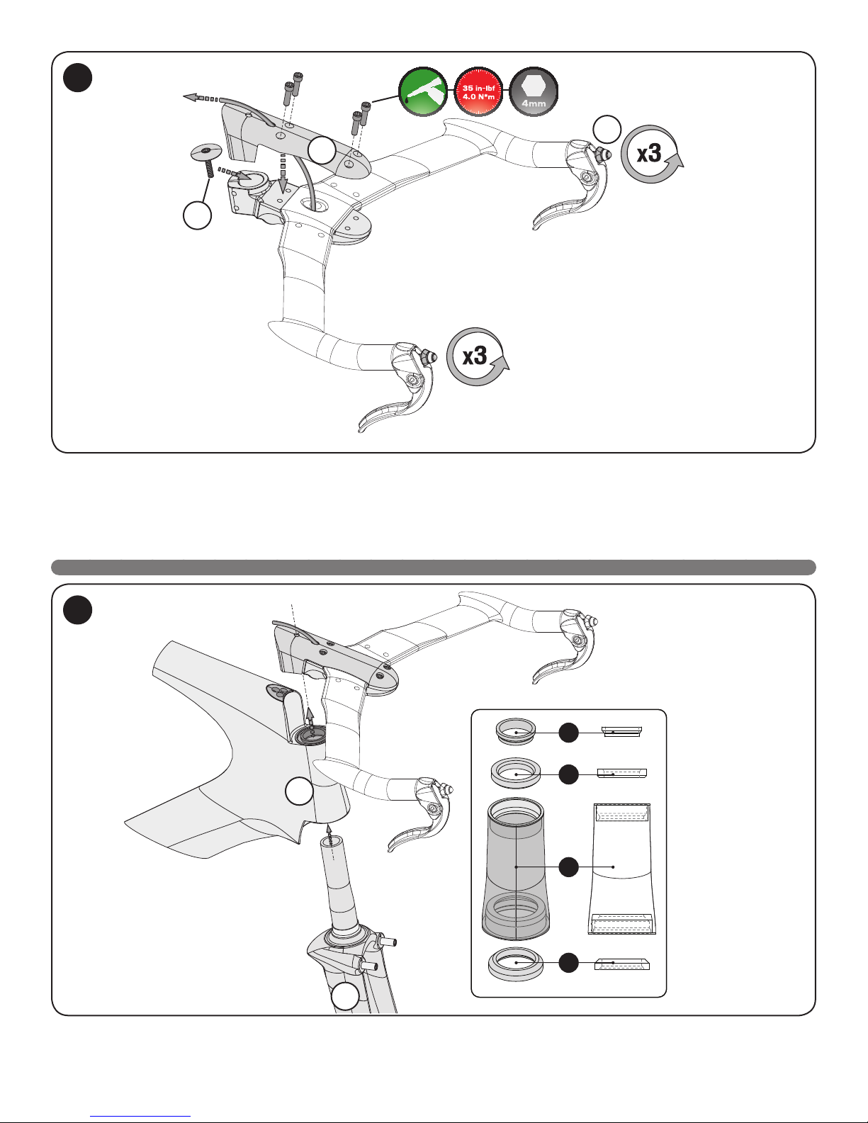
1.3 INSTALLING THE HANDLEBAR ON THE STEM . . . . . . . . . . . . . . . . . . . . . . . . . . . . . . . . . . . . . . . . 7
1.4 INSTALLING THE FRONT END ASSEMBLY ON THE FRAME. . . . . . . . . . . . . . . . . . . . . . . . . . . . 8
CHAPTER 2: BRAKE INSTALLATION ........................................................10
2.1 FRONT AND REAR BRAKE ASSEMBLY (Exploded view) . . . . . . . . . . . . . . . . . . . . . . . . . . . . . . . . 10
2.2 FRONT AND REAR BRAKE ASSEMBLY (Spring mechanism) . . . . . . . . . . . . . . . . . . . . . . . . . . . 10
2.3 INSTALLING THE FRONT BRAKE ASSEMBLY. . . . . . . . . . . . . . . . . . . . . . . . . . . . . . . . . . . . . . . . . 11
2.4 INSTALLING THE REAR BRAKE ASSEMBLY . . . . . . . . . . . . . . . . . . . . . . . . . . . . . . . . . . . . . . . . . . 13
CHAPTER 3: HANDLEBAR EXTENSION INSTALLATION . . . . . . . . . . . . . . . . . . . . . . . . . . . . . . . . . . . . . . . . . 15
3.1 INSTALLING THE AERO EXTENSIONS (Option 1 - no risers, with our without spacers) . . . . . . 15
3.2 INSTALLING THE RISERS AND CROSSBAR . . . . . . . . . . . . . . . . . . . . . . . . . . . . . . . . . . . . . . . . . . 16
3.3 INSTALLING THE AERO EXTENSIONS (Option 2 - risers with or without spacers) . . . . . . . . . 17
3.4 AERO EXTENSIONS WITH SPACERS AND RISERS - FULL RANGE . . . . . . . . . . . . . . . . . . . . 17
3.5 INSTALLING THE ARMRESTS ........................................................18
CHAPTER 4: SEATPOST INSTALLATION .....................................................19
4.1 INSTALLING THE SEATPOST CRADLE ASSEMBLY IN THE SEATPOST . . . . . . . . . . . . . . . . . 19
4.2 ADJUSTING THE SEATPOST TILT ANGLE AND FORE-AFT POSITIONS . . . . . . . . . . . . . . . . 19
4.3 INSTALLING THE SEATPOST COLLAR AND SHIM. . . . . . . . . . . . . . . . . . . . . . . . . . . . . . . . . . . . . 20

Page 2 of 20
HARDWARE
QTY SIZE BOLT (to-scale art) USE WITH
4 M6 x 65mm Handlebar + 40mm spacers + extension
4 M6 x 60mm Handlebar + 35mm spacers + extension
4 M6 x 55mm
Handlebar + 30mm spacers + extension, or
Crossbar + 40mm spacers + extension
4 M6 x 50mm
Handlebar + 25mm spacers + extension, or
Crossbar + 35mm spacers + extension
4 M6 x 45mm
Handlebar + 20mm spacers + extension, or
Crossbar + 30mm spacers + extension
4 M6 x 40mm
Handlebar + 15mm spacers + extension, or
Crossbar + 25mm spacers + extension
4 M6 x 35mm
Handlebar + 10mm spacers + extension, or
Crossbar + 20mm spacers + extension
8 M6 x 30mm
Handlebar + 5mm spacers + extension, or
Crossbar + 15mm spacers + extension
4 M6 x 25mm
Handlebar + extension, or
Crossbar + 10mm spacers + extension
4 M6 x 20mm Crossbar + 5mm spacers + extension
8 M6 x 15mm Crossbar + extension
4 M4 x 10mm Pad holder to extension
6 M5 x 23mm Stem cap to stem base

Page 3 of 20
PRODUCT
RISER
TOP VIEW 2 x 35mm RISER 2 x 45mm RISER 2 x 55mm RISER 2 x 65mm RISER
RISER CAP
SIDE VIEW 1 x LEFT TOP CAP 1 x LEFT BOTTOM CAP
RISER CAP
SIDE VIEW 1 x RIGHT TOP CAP 1 x RIGHT BOTTOM CAP
LEFT SPACER
TOP VIEW 1 x 20mm SPACER 1 x 10mm SPACER 2 x 5mm SPACER
RIGHT SPACER
TOP VIEW 1 x 20mm SPACER 1 x 10mm SPACER 2 x 5mm SPACER

Page 4 of 20
GEOMETRY
Due to the innovative design of the Specialized Shiv TT, the parameters that a bike fitter uses to match a bike to a rider’s body are adjusted in different
ways than on a traditional TT/Tri bike.
There are three key changes from a traditional TT bike fit that make the Shiv TT unique compared to a typical bike when deciding a rider’s frame size:
1. The 5 different frame sizes increase only in Reach (or the horizontal length from the BB to the center of the HT) -- the lowest Stack (the vertical
dimension from BB to the center-top of the HT) is fixed for all sizes.
You chose bike size based upon reach and can micro adjust stack up from this lowest position to match the rider’s preferred aerobar placement.
2. The Stack of the aerobar extensions is adjustable (115mm of vertical adjustment) and moves vertically – NOT in-line with the steer tube as on a
traditional front end. For example:
On a Transition, if you add a 10mm spacer to the steerer tube at 73 degrees, you’ve increased the vertical stack of the bar 9.5mm and shortened
the reach 3mm.
On a Shiv TT, if you add a 10mm spacer, you have increased the vertical stack 10mm and the reach is still the same.
3. There is only one “stem” length and angle for all sizes of bike: 75mm, -18 degree.
This fixes the basebar to one position that is non-adjustable for each frame size.
Aerobar pads and extensions can be raised up from here (up to 115mm vertically).
Flipping the aerobar pads gives 22mm of reach adjustment.
Please review the attached geo chart for detailed bike measurements.
It is highly recommended that you fit a prospective Shiv TT rider on a fit cycle or a Transition before ordering a Shiv TT size. Once a rider is fit,
measuring effective reach from BB to center of aerobar pad will dictate which size bike the rider needs.
The sizes are denoted by their effective reach to the center of the aerobar pad: 450mm, 465 mm, 480 mm, 495 mm, and 515 mm. Additionally, TT
length is supplied in the geo chart for those who use this parameter.

Page 5 of 20
3
64
8
16
9
19
11 12
13
10 7
14
15
5
1B 1A
2B
2A
18
17
20
SIZE 450 (XS) 465 (SM) 480 (MD) 495 (LG) 515 (XL)
1A Effective Reach to Center of Pad, FORWARD Position (mm)** 450 465 480 495 515
1B Effective Reach to Center of Pad, REARWARD Position (mm)** 428 443 458 473 493
2A Effective Stack to Pad Holder, LOWEST Position (mm) 534 543 543 543 543
2B Effective Stack to Pad Holder, HIGHEST Position (mm) 649 658 658 658 658
3Frame Reach (mm) 375 390 405 420 440
4Frame Stack (mm) 486 495 495 495 495
5Stem Length, -18° Horizontal (mm) 75 75 75 75 75
6Seat Tube Length, BB Center to Top (mm) 504 564 563 562 560
7Top Tube Length (mm)* 512 525 535 542 557
8BB Drop (mm) 71 72 72 72 72
9Chainstay Length (mm) 395 395 395 395 395
10 Seat Tube Angle (°) 74.5° 74.5° 75° 75.75° 76.25°
11 Head Tube Angle (°) 71° 72° 72° 72° 72°
12 Fork Rake (mm) 47 43 43 43 43
13 Trail (mm) 68 65 65 65 65
14 Front-Center (mm) 575 577 592 607 629
15 Wheelbase (mm) 940 946 961 976 996
16 Standover Height (mm) 745 806 806 806 806
17 Head Tube Length (mm) 90 100 100 100 100
18 Seatpost Setback (mm) 20 20 20 20 20
19 Seatpost Length (mm) 400 400 400 400 400
20 Front of ST to Rear of Stem/TT Cutout (To identify frame size) N/A 479 490 496 514
* TT is measured horizontally from center of HT to center of ST
** Switching the left and right arm pads allows for 22mm in reach adjustment from forward to rearward position

Page 6 of 20
CHAPTER 1: HANDLEBAR / STEM INSTALLATION
1.1 INSTALLING THE CABLES IN THE HANDLEBAR
35cm150cm
1. Cut the front brake cable housing (1-A) to 35cm length. The final housing length may need to be trimmed, based on the brand of brake levers (fig.3).
2. Cut the rear brake cable housing (1-B) to 150cm length. The final housing length will be to be trimmed during the rear brake installation.
3. Run the front brake cable (1-C) backward inside the front brake cable housing.
4. Install the front cable housing, from the underside of the handlebar (1-D) through the center hole, by first running the brake cable through the
handlebar, then pushing the cable housing through. The cable can be used to help pull the housing through as well.
5. Repeat for the rear cable housing, but through the top of the center hole of the handlebar.
6. Make sure the cable housings stick out at the brake lever end by about 2” to engage the cable housing slot in the brake lever.
7. Once the housings are installed in the handlebar, remove the front and rear brake cables from inside the cable housings.
1
1-D
1-B 1-C 1-A
2
Front
Rear

Page 7 of 20
1.2 INSTALLING THE BRAKE LEVERS IN THE HANDLEBAR
8. Engage the cable housings into the left and right brake levers (1-E). Depending on the brake lever choice, install a brake cable ferrule (1-F) if necessary.
9. Push the cable housing back through the handlebar with the levers, while pulling the housing out from the handlebar’s center hole. Make sure that
the cable housing is fully engaged in the lever body and the lever body is fully engaged in the handlebar.
10. Torque to 50 in-lbf (5.6 N*m).
1.3 INSTALLING THE HANDLEBAR ON THE STEM
11. Guide the front brake cable housing and ferrule into the stem base’s center hole and place the handlebar onto the stem base. Depending on the
chosen brake levers, the cable housing may need to be trimmed to fit, to make sure the cable housing has a smooth, natural path into the stem.
12. Install the front an rear brake cables into the brake levers and through the cable housings.
13. Thread the front brake cable through the stem cable hole (1-G).
1-E
1-F
1-G
3
4

Page 8 of 20
14. Grease the top cap bolt threads, then place the steerer tube compression top cap and bolt (1-H) on top of the stem base.
15. Run the rear brake cable housing through the oval hole in the carbon stem cap (1-I), so that the cable sits inside the groove in the underside of the
stem cap.
16. Grease then install 4 stem cap bolts (M5 x 23mm). Torque to 35 in-lbf (4.0 N*m).
17. Unthread each brake lever barrel adjuster (1-J) 3 turns from full tight.
18. Pull the front cable back and forth to make sure the cable moves smoothly and doesn’t bind.
1.4 INSTALLING THE FRONT END ASSEMBLY ON THE FRAME
1
2
3
4
19. Install the headset parts (see sidebar) in the head tube.
20. Install the fork (1-K) into the head tube (1-L).
5
6
1-L
1-I
1-J
1-H
1-K
1. 1” Compression ring
(Custom for Shiv TT)
2. 1” Cartridge bearing
(Cane Creek)
3. Shiv TT Head tube
4. 1 1/8” Cartridge bearing
(Campy standard)

Page 9 of 20
21. Install the stem/handlebar assembly onto the fork steerer tube.
NOTE: The headset compression bolt is located between the stem’s upper and lower sections. Tighten the compression bolt to draw the stem assembly
down onto the steerer tube. Make sure not to cross-thread the bolt.
22. Adjust the headset compression bolt to eliminate headset play.
23. Grease, then torque the stem steerer tube bolts to 40 in-lbf (4.5 N*m).
7
8

Page 10 of 20
CHAPTER 2: BRAKE INSTALLATION
2.1 FRONT AND REAR BRAKE ASSEMBLY (Exploded view)
Rear non-drive side Rear drive side
1 2 3 4 5 6 7
Front non-drive side Front drive side
2.2 FRONT AND REAR BRAKE ASSEMBLY (Spring mechanism)
1. Place the spring plates (5) in the brake cavity. Make sure they’re facing the correct direction with the flat edge against the adjuster screw. The spring
plate is reversible for either side brake.
2. Install the springs (6), clockwise for the drive-side brake, counter-clockwise for the non-drive-side brake. The shorter of the two spring pins goes in
the brake.
3. Install the brake spring covers (7).
1. Aero bolt cap
2. Brake bolt O-ring
3. Brake pivot bolt
4. Brake arm
5. Spring plate
6. Spring
7. Spring cover
1
5
6
7
Place long spring
tip facing out
Clockwise
wound
Counter-clockwise
wound
NON-DRIVE SIDE (Rear View) DRIVE SIDE (Rear View)

Page 11 of 20
2.3 INSTALLING THE FRONT BRAKE ASSEMBLY
4. Install the drive-side brake arm (2-A) with the tip of a flat head screwdriver (ideally with a machined groove); rotate the spring tab into place.
5. Install a brake bolt and washer, then torque to 70 in-lbf (7.9 N*m).
6. Install the o-ring on the brake bolt if it’s not already on, then install the aero cap.
7. Rotate the drive-side brake arm (2-A) counter-clockwise to allow the non-drive-side brake arm (2-B) to install on the brake boss.
8. Install the spring tab into the tab hole.
2
3
2-A
2-A
2-B

Page 12 of 20
9. Install the washer and bolt, torque to 70 in-lbf (7.9 N*m).
10. Install the o-ring on the brake bolt if it’s not already on, then install the aero cap.
1-2mm 1mm
11. Install the front wheel in the fork tabs.
12. Adjust the pad position so that the top of the pad is 1-2mm below the top of the rim’s braking surface and flat against the rim surface.
13. Torque the brake pad bolts to 43 in-lbf (4.9 N*m)
14. Hook the articulated cable hanger arm (2-C) to the brake arm.
15. Install the front brake cable into the cable hanger.
16. Position the brake pads so that they’re approximately 1mm away from the braking surface.
17. TIghten the cable hanger bolts to pinch the cable, using two 2.5mm Allen keys, or one 2.5mm Allen key and one 8mm open-ended wrench.
18. Adjust the spring tension screws with a 2mm Allen key to center the brake pads relative to the rim.
4
5
OR
2-C

Page 13 of 20
2.4 INSTALLING THE REAR BRAKE ASSEMBLY
1. Run the rear brake cable and brake cable housing through the larger center hole behind the stem.
2. Continue running the cable housing into the frame until it emerges from the underside of the downtube in front of the bottom bracket.
3. Adjust the housing path from the stem to the top tube so that the curve is as low profile as possible without causing kinks in the housing or pulling
the housing out of the stem or top tube when turning the stem.
4. Install the rear brake arms, following the same steps as the front brake installation (fig.1-4).
5. Place the flexible cable noodle (2-D) in the cable noodle guide and trim the cable housing so that it has a smooth path to the cable noodle that’s as
short as possible while still fully seating in the noodle. Make sure it stays fully seated through the entire range of the brake, from closed to open.
NOTE: Make sure the cable is retracted far enough into the cable housing so that the cable is not cut when trimming the cable housing.
6
7
2-D

Page 14 of 20
6. Adjust the angle and height of the brake pads against the rim, same as the front brake (fig.5 & 9).
7. Tighten the brake pad bolts (fig.9).
NOTE: The rear drive-side brake pad bolt requires a 10mm wrench to tighten.
8. Run the cable through the noodle and loop it around the pinch bolt.
9. Adjust the clearance between the rim and the pads to approximately 1mm on each side (fig.9).
10. Torque the cable pinch bolt to 55 in-lbf (6.2 N*m).
1-2mm1mm
11. Adjust the spring tension screws with a 2mm Allen key to center the brake pads relative to the rim.
12. Make sure the spring tension screws are inset enough so that the drive side clears the chainring.
8
9

Page 15 of 20
CHAPTER 3: HANDLEBAR EXTENSION INSTALLATION
In addition to frame size options (different reach), the Shiv TT handlebar assembly is adjustable vertically (stack adjustment) and horizontally (reach
adjustment).
The stack is vertically adjustable (not in line with the steerer tube), so that stack height adjustments do not affect the reach of the bicycle.
Stack height can be configured with the following options:
Extensions with no risers, with or without spacers (0-40mm in 5mm increments)
Extensions with risers, with or without spacers (45 to 115mm in 5mm increments. Maximum of 75mm of risers and 40mm of spacers)
Additionally, the pad holders can be configured with the following options:
Laterally from the center position by +/- 14mm, for a total width adjustment of 28mm.
Fore-aft, in either a forward or rearward setting, for a total reach adjustment of 22mm.
The lateral extension width with no risers is 80mm.
The lateral extension width with risers and crossbar is 110mm, due to the crossbar mounting holes being set further away from center.
WARNING! Be sure to select the appropriate bolt length to match the desired risers and/or spacers at each point, as shown in the
accompanying tables. Incorrect bolt lengths can result in failure, which may lead to serious personal injury or death.
3.1 INSTALLING THE AERO EXTENSIONS (Option 1 - no risers, with our without spacers)
5mm
5
15mm
5
10
20mm
20
10mm
10
25mm
5
20
30mm
10
20
35mm
5
10
20
5
5
10
20
40mm
AA
AA
1. Grease then install 4 bolts (A). Bolt length varies according to desired spacers (5-40mm in 5mm increments), if any (Table Option 1).
2. Torque the bolts to 80 in-lbf (9.0 N*m).
Extensions (3-A) and spacers (3-B) are specific to left and right sides. Make sure the spacers’ curves fit the extensions and handlebar
or wing correctly.
Lateral extension width is set at 80mm when only using extensions (no risers) with or without spacers (see fig.4).
3. If more than 40mm of stack height is required, refer to page 16 (fig.2) and page 17 (fig.3).
1
OPTION 1:
Bolts (A) into Extensions,
with or without spacers,
no risers
Spacer
Height
Bolt
Length
0 25
5 30
10 35
15 40
20 45
25 50
30 55
35 60
40 65
3-A
3-B

Page 16 of 20
3.2 INSTALLING THE RISERS AND CROSSBAR
35 45 55 65
45mm
Upper
Riser
Cap
35mm Riser
Lower
Riser
Cap
55mm
45mm Riser
65mm
55mm Riser
75mm
65mm Riser
Crossbar
Handlebar
Riser height includes crossbar thickness, measured from top of handlebar to top of crossbar.
CC
CC
BB
BB
The risers (3-C) cover the 45-75mm range in 10mm increments. The riser height measurements (45 / 55 / 65 / 75mm) include the
thickness of the riser caps (x2) and the crossbar. The riser extensions alone measure 10mm less than the final measurement (fig.2 inset).
Lateral extension width is set at 110mm when using risers and crossbar (see fig.4).
1. Riser bolts thread directly into the risers from above (15mm, through the riser crossbar (3-E)) and below (30mm, through the handlebar (3-F)).
2. Grease then place 4 riser bolts (B) (M6 x 15mm) through the inner bolt holes of the crossbar from above, then through the riser caps (3-D) and into
the top of the riser (3-C). Riser caps are specific to top, bottom, left and right.
3. Torque the bolts to 80 in-lbf (9.0 N*m).
To ease installation (especially with shorter risers), install the extensions and desired spacers (see step 3.3, page 17) onto the crossbar
before installing the risers to the handlebar.
4. Grease then place 4 riser bolts (C) (M6 x 30mm) through the holes in the handlebar from below, then through the riser caps (3-D) and into the
underside of the risers (3-C).
5. Torque the bolts to 80 in-lbf (9.0 N*m).
3-D
3-F
Bolts (B) through
crossbar, into risers
Riser
Height
Bolt
Length
45, 55, 65, 75 15
Bolts (C) through
base bar, into risers
Riser
Height
Bolt
Length
45, 55, 65, 75 30
2
3-E
3-C

Page 17 of 20
2
3.3 INSTALLING THE AERO EXTENSIONS (Option 2 - risers with or without spacers)
DD
1. Spacers (3-B) and risers (3-C) can be combined to offer a full 0-115mm range in 5mm increments (40mm of spacers and 75mm of risers).
Spacers and extensions are specific to left and right sides. Make sure the spacers’ curves fit the extensions and handlebar or crossbar
correctly.
2. Install the risers and crossbar as covered in step 3.2 (page 16, fig.2).
3. Install 4 spacer bolts (D) with the length corresponding to the chosen spacers.
4. Torque bolts to 80 in-lbf (9.0 N*m).
3.4 AERO EXTENSIONS WITH SPACERS AND RISERS - FULL RANGE
The lateral width of the extensions is set either at 80mm when mounted directly to the handlebars (with or without spacers) or at 110mm
when using the crossbar and risers (with or without spacers).
The vertical height range of the extensions is 115mm.
3-C
3
4
OPTION 2:
Bolts (D) into Extensions,
with or without spacers,
with risers
Spacer
Height
Bolt
Length
0 15
5 20
10 25
15 30
20 35
25 40
30 45
35 50
40 55
3-B

Page 18 of 20
3.5 INSTALLING THE ARMRESTS
Center of armrest
Lateral extension width
122mm (No risers), 152mm (With risers)
150mm (No risers), 180mm (With risers)
178mm (No risers), 208mm (With risers)
Distance center-to-center of arm pads
LATERAL PAD WIDTH
14mm
14mm
1. The armrests (3-G) are laterally and fore-aft adjustable.
- Lateral adjustment range: Narrow (Position 1), Medium (Position 2, +14mm per side) and Wide (Position 3, +28mm per side).
- Fore-aft adjustment range: Switching the left and right armrests provides 22mm of adjustment.
2. Grease then install 4 armrest bolts (M4 x 10mm).
3. Torque to 18 in-lbf (2.0 N*m).
4. Install the soft armrest cushions.
5
Fore-aft
adjustment
Lateral
adjustment
Rearward
setting
Forward
setting
3-G
Table of contents
Popular Exercise Bike manuals by other brands

Sportplus
Sportplus SP-FB-1000 operating instructions

Spirit
Spirit XBR25 owner's manual

BH FITNESS
BH FITNESS H674B Instructions for assembly and use

BH FITNESS
BH FITNESS H832U Instructions for assembly and use

Diamondback
Diamondback 300U Owner's manual and assembly guide

Precor
Precor RBK 615 Assembling and maintaining

Weslo
Weslo Easy Fit WLIVEX57010.0 user manual

Xterra
Xterra SB4.5r owner's manual

Spirit Medical Systems Group
Spirit Medical Systems Group MR100 user manual

Livestrong
Livestrong LS6.0R Service manual

Taurus
Taurus TF-ERGO-X Assembly and operating instructions

Sunny Health & Fitness
Sunny Health & Fitness SF-B1709 user manual