Sabiana MB BOARD User manual

B 11/12
E 05/13
Cod. 4050532EST
MANUALE D’USO SCHEDA MB
PER VENTILCONVETTORI CASSETTE
MB BOARD
FOR CASSETTE FAN COILS, USER MANUAL
NOTICE D’UTILISATION DE LA CARTE MB
POUR VENTILO-CONVECTEURS CASSETTE
DESkA MB PRO KAZETOVÝ FANCOIL
NÁVOD NA INSTALACI A ÚDRŽBU
MANUAL DE USO
DE LA TARJETA MB PARA
LOS VENTILADORES CONVECTORES
CASSETTE
HANDLEIDING MB kAART
VENTILATORS-CONVECTORS
CASSETTE

2 2A
L’apparecchio non è destinato ad
essere usato da persone (bambini
compresi) le cui capacità fisiche,
sensoriali o mentali siano ridotte,
oppure con mancanza di esperienza
o di conoscenza, a meno che esse
abbiano potuto beneficiare, attra-
verso l’intermediazione di una perso-
na responsabile della loro sicurezza,
di una sorveglianza o di istruzioni
riguardanti l’uso dell’apparecchio.
I bambini devono essere sorvegliati
per sincerarsi che non giochino con
l’apparecchio.
This unit is not intended for use by
persons (including children) with
reduced physical, sensory or mental
capabilities, or lack of experience
and knowledge, unless they have
been given supervision or instruction
concerning use of the appliance by
a person responsible for their safety.
Children should be supervised to
ensure that they do not play with
the appliance.
L’appareil n’est pas prévu pour être
utilisé par des personnes (y compris
les enfants) dont les capacités physi-
ques, sensorielles ou mentales sont
réduites, ou dénuées d’expérience
ou de connaissance, sauf si elles
ont pu bénéficier, par l’intermédiaire
d’une personne responsable de
leur sécurité, d’une surveillance ou
d’instructions préalables concernant
l’utilisation de l’appareil.
Il convient de surveiller les enfants
pour s’assurer qu’ils ne jouent pas
avec l’appareil.
Zařízení není určeno pro použití
osobami (včetně dětí), které mají
snížené psychické, senzomotorické
nebo mentální schopnosti nebo
osobami s nedostatkem zkušeností
či schopností vyjma situací, kdy
dozor a provoz zařízení je zajištěn
osobou, která je odborně způsobilá
a nebo je zaškolena pro bezpečný
provoz zařízení.
Děti musí být pod dozorem, aby
bylo zajištěno, že si nebudou se
zařízením hrát.
Este aparato no debe ser utilizado
por personas (incluidos niños) cuyas
capacidades físicas, sensoriales o
mentales estén disminuidas o que
carezcan de experiencia y cono-
cimientos, al no ser que ellas hayan
podido beneficiar, a través de la
intermediación de una persona
responsable de su seguridad, de
una vigilancia o de instrucciones
relativas al uso del aparato.
Los niños han de vigilarse para
asegurarse de que no jueguen con
el aparato.
Het apparaat is niet bestemd voor
gebruik door personen (kinderen
inbegrepen) met beperkte fysieke,
sensoriële of mentale capaciteiten
of met onvoldoende ervaring of
kennis, tenzij ze gebruik hebben
kunnen maken, dankzij het toedoen
van iemand die verantwoordelijk is
voor hun veiligheid, van toezicht
of aanwijzingen over het gebruik
van het apparaat.
Kinderen dienen onder toezicht te
staan om zich ervan te verzekeren
dat zij niet met het apparaat spelen.
SI RACCOMANDA
DI LEGGERE ATTENTAMENTE
QUESTE ISTRUZIONI
PRIMA DI UTILIZZARE
IL COMANDO
READ
THESE INSTRUCTIONS
CAREFULLY
BEFORE USING
THE CONTROL
NOUS
VOUS RECOMMANDONS
DE LIRE ATTENTIVEMENT
CES INSTRUCTIONS
AVANT D’UTILISER
LA COMMANDE
HET IS RAADZAAM DEZE
HANDLEIDING AANDACHTIG
TE LEZEN ALVORENS
DE BEDIENING
TE GEBRUIKEN
LE RECOMENDAMOS
QUE LEA ATENTAMENTE
ESTAS INSTRUCCIONES
ANTES DE USAR
EL MANDO
INDICE
Scopo
Scheda elettronica
Funzione
dei contatti ausiliari
Impostazione
Dip di configurazione
Tabella segnalazione LED
Configurazione di default
Funzione Autofan
Funzionamento Master-Slave
Istruzioni operative
per il collegamento
con linea seriale RS485
Note di installazione
Messa a terra della rete
Accessori
Legenda
Schemi di collegamento
Logica di funzionamento
con resistenza elettrica
Montaggio
del ricevitore sulla plafoniera
Montaggio
della plafoniera sul cassette
Batterie
Note generali
Impostazione orologio
Impostazione del set desiderato
Impostazione della ventilazione
Modalità di funzionamento
Timer
Comando a parete T–MB
2
3
4
5
5
6
6
7
8
8
10
11
12
13
15
19
19
20
21
23
24
25
26
27
29
SCOPO
CONTENTS
Scope
Electronic board
Function
of the auxiliary contacts
Setting
the configuration dipswitches
LED signal table
Default configuration
Autofan function
Master-Slave operation
Operating instructions
for connection
via an RS485 serial line
Installation notes
Earthing the network
Accessories
Legend
Connection diagrams
Operating logic
with electrical heater
Mounting
the receiver on the support
Mounting
the support on the cassette
Batteries
General notes
Setting the clock
Setting the set point
Setting the fan mode
Operating modes
Timer
T–MB wall-mounted controller
2
3
4
5
5
6
6
7
8
8
10
11
12
13
15
19
19
20
21
23
24
25
26
27
29
SCOPE
SOMMAIRE OBSAH ÍNDICE INHOUD
BUT OBJETIVO DOEL
But
Carte électronique
Fonction
des contacts auxiliaires
Programmation dipswitches
Tableau de signalisation LED
Configuration par défaut
Fonction Autofan
Fonctionnement Maître-Esclave
Instructions
pour le raccordement
avec ligne série RS485
Notes d’installation
Mise à la terre du réseau
Accessoires
Légende
Schémas de raccordement
Logique de fonctionnement
avec resistance électrique
Montage
du récepteur sur le support
Montage
du support sur la cassette
Piles
Notes
Programmation horloge
Programmation de
la température consigne voulue
Programmation de la ventilation
Modes de fonctionnement
Timer
Commande murale T–MB
2
3
4
5
5
6
6
7
8
8
10
11
12
13
15
19
19
20
21
23
24
25
26
27
29
Účel použití
Deska elektroniky
kazetového fancoilu
Funkce
dodatkových kontaktů
Kongurace DIP přepínačů
Tabulka LED signalizace
Výrobní nastavení
Funkce automatického ventilátoru
Zapojení Master/Slave
Provozní
pokyny pro připojení po sériové
lince přes RS485
Poznámky k instalaci
Uzemnění komunikační sítě
Příslušenství
Legenda
Připojovací schémata
Provozní režim
elektrického ohřevu
Instalace IR přijímače
Připojení IR přijímače k zařízení
Baterie
Všeobecné poznámky
Nastavení hodin
Nastavení
požadované teploty vzduchu
Nastavení
provozního režimu ventilátoru
Nastavení provozního režim
Nastavení časového programu
Nástěnné ovládání T-MB
2
3
4
5
5
6
6
7
8
8
10
11
12
13
15
19
19
20
21
23
24
25
26
27
29
Objetivo
Tarjeta electrónica
Función
de los contactos auxiliares
Programación
Dip de configuración
Tabla indicación LED
Configuración por defecto
Función Autofan
Funcionamiento Master-Slave
Instrucciones operativas
para la conexión
con línea en serie RS485
Notas de instalación
Puesta a tierra de la red
Accesorios
Leyenda
Esquemas de conexión
Lógica de funcionamiento
con resistencia eléctrica
Montaje
del receptor en el plafón
Montaje
del plafón en el cassette
Baterías
Notas generales
Programación del reloj
Programación del set deseado
Programación de la ventilación
Modalidad de funcionamiento
Temporizador
Control de pared T–MB
2
3
4
5
5
6
6
7
8
8
10
11
12
13
15
19
19
20
21
23
24
25
26
27
29
Doel
Elektronische fiche
Functie
van de hulpcontacten
Instelling
configuratieschakelaars
Tabel LED signalering
Defaultconfiguratie
Functie Autofan
Werking Master-Slave
Aanwijzingen
voor de aansluiting
met seriële lijn RS485
Opmerkingen bij de installatie
Aarding van het netwerk
Accessoires
Legende
Aansluitschema’s
Functioneringslogica
met elektrische weerstand
Montage
plafondelement op cassette
Montage
ontvanger op plafondelement
Batterijen
Algemene opmerkingen
Instelling klok
Instelling van de gewenste set
Instelling ventilatie
Werkwijze
Timer
Commando aan wand T–MB
2
3
4
5
5
6
6
7
8
8
10
11
12
13
15
19
19
20
21
23
24
25
26
27
29

CA CF
D0-D0
0/10VD2
WP D1 J1
T2
T1
T3
CA CF
D0-D0
D2
WP D1 J1
T2
T1
T3
3 3A
LEGENDA:
D1 =
Dip Switch di configurazione
D2 = Dip Switch di indirizzo
J1 = Jumper MC2
T1 = Sonda aria (posta
in ripresa dell’apparecchio)
T2 = Sonda Change-Over
(optional)
T3 = Sonda di minima
(di default non attiva)
CF = F2-F2 Contatto pulito
finestra aperta / presenza
persona.
Se aperto l’unità si ferma
CA = F1-F1 ON-OFF remoto
oppure Change-Over
estate/inverno remoto
(Vedi impostazione DIP 9)
RS485 = Morsetti 0/D-/D+
per il collegamento
seriale RS485
0/10 = Uscita segnale 0-10V
per controllo inverter
(per motori ECM)
WP = Pompa
di evacuazione consensa
KEY:
D1 = Configuration dipswitches
D2 = Address dipswitches
J1 = Jumper MC2
T1 = Air probe (fitted
at the appliance intake)
T2 = Change-Over probe
(optional)
T3 = Minimum probe
(disabled by default)
CF = F2-F2 Window
open / person presence
voltage-free contact.
If open the unit stops
CA = F1-F1 remote ON-OFF
or remote summer/winter
Change-Over (See DIP 9
setting)
RS485 = Terminals 0/D-/D+
for the RS485 serial
connection
0/10 = 0/10 V output signal
for inverter control
(ECM motors)
WP = Condensate pump
LÉGENDE:
D1 = Dip Switch de configuration
D2 = Dip Switch d’adresse
J1 = Jumper MC2
T1 = Sonde air (placée
sur la reprise de l’appareil)
T2 = Sonde Change-Over
(option)
T3 = Sonde de température
minimale (par défaut
pas active)
CF = F2-F2 Plot libre fenêtre
ouverte/détection présence.
S’il est ouvert l’unité s’arrête
CA = F1-F1
MARCHE/ARRÊT à
distance ou bien changement
de marche été/hiver à distance
(Voir réglage DIP 9)
RS485 = Bornes 0/D-/D+
pour le raccordement
série RS485
0/10 = Sortie du signal 0-10V
pour contrôle onduleur
(pour moteurs ECM)
WP = Pompe d’evacuation
des condensats
LEGENDA:
D1 = Kongurační DIP přepínače
D2 = Adresovací DIP přepínače
J1 = Kontakt MC2
T1 = Čidlo vzduchu (instalováno
ve výrobě do přívodu
vzduchu do fancoilu)
T2 = CH15-25 termostat (jako
objednávkové příslušenství)
T3 = Termostat minimální teploty
(Instalován z výroby -
Standardně deaktivován)
CF = F2-F2 okenní
kontakt / přítomnost osob.
Je-li rozepnut,
jednotka stojí
CA =
F1-F1 vzdálené ON-OFF ovládání,
nebo vzdálené přepnutí léto/zima
pomocí Change-Over
(viz. nastavení DIP9)
RS485 = Svorkovnice 0/D-/D+
pro sériové
propojení přes RS485
0/10 = výstupní signál 0/10 V
pro ovládání invertoru
(EC motory)
WP = čerpadlo kondenzátu
LEYENDA:
D1 =
Dip Switch de configuración
D2 = Dip Switch de dirección
J1 = Jumper MC2
T1 = Sonda aire (colocada
en reanudación del aparato)
T2 = Sonda Change-Over
(opcional)
T3 = Sonda de mínima
(por defecto no activa)
CF = F2-F2 Contacto limpio
ventana abierta / presencia
persona. Si está abierto
la unidad se para
CA = F1-F1 ON-OFF remoto
o bien Change-Over
verano/invierno remoto
(Ver configuración de DIP 9)
RS485 = Bornas 0/D-/D+
para la conexión
en serie RS485
0/10 =
Señal de Salida de 0-10V
para el control del conver-
tidor (para motores ECM)
WP = Bomba de evacuación
de condensados
LEGENDE:
D1 =
Dimschakelaar configuratie
D2 =
Dimschakelaar bestemming
J1 = Jumper MC2
T1 = Luchtsonde
(vlakbij het apparaat)
T2 = Sonde Change-Over
(optie)
T3 = Minimumsonde
(default niet actief)
CF = F2-F2 Schoon contact
open raam / aanwezigheid
persoon. Indien open stopt
de eenheid
CA = F1-F1 ON-OFF remote
of Omschakeling
zomer/winter
(Zie instelling DIP 9)
RS485 = Klemmen 0/D-/D+
voor de seriële
aansluiting RS485
0/10 = Uitgang signaal 0-10V
voor controle inverter
(voor ECM motoren)
WP = Condensatwaterpomp
SCHEDA
ELETTRONICA
ELECTRONIC
BOARD
CARTE
ELECTRONIQUE
DESKA
ELEKTRONIKY
TARJETA
ELECTRÓNICA
ELEKTRONISCHE
FICHE
Motore Asincrono A 3 velocità
three- speed Asynchronous Motor
Moteur Asynchrone à 3 vitesses
Tří oTáčkový asynchronní moTor
Motor Asíncrono A 3 velocidAd
Asynchrone Motor Met 3 snelheden
12
1
M
otore
e
lettronico
ecM
ecM electronic Motor
Moteur electronique ecM
ec
Motor
Motor electrónico ecM
elektroMotor ecM
2

D0-D0
CA
CF
Contatto CA [F1-F1]:
ON-OFF remoto
oppure Change-Over
Estate/Inverno remoto
(vedi impostazione DIP 9).
- con DIP N.ro 9 in OFF
è configurato come ON/OFF
remoto dove:
• contatto aperto = ON
• contatto chiuso = OFF
- con DIP N.ro 9 in ON
è configurato come
Estate/Inverno dove:
• In 1 aperto = Inverno
• In 1 chiuso = Estate
Contatto CF (F2-F2):
- contatto finestra aperta
- sonde presenza persona
- un altro sistema
A contatto chiuso
l’apparecchio funziona.
A contatto aperto
l’apparecchio si ferma.
Se utilizzato,
togliere il Jumper MC1
di chiusura del contatto.
Contact CA [F1-F1]:
Remote ON-OFF
or remote Summer/Winter
Change-Over
(See DIP 9 setting).
- with DIP No 9 set on OFF
is configured
as remote ON/OFF where:
• contact open = ON
• contact closed = OFF
- with DIP No 9 set on ON
is configured
as Summer/Winter where:
• In 1 open = Winter
• In 1 closed = Summer
Contact CF (F2-F2):
- window open contact
- person presence sensors
- other systems
When the contact is closed
the appliance can operate.
When the contact is open
the appliance is stopped.
If used,
remove the MC1 Jumper
for contact closure.
Contact CA [F1-F1]:
MARCHE-ARRÊT à distance
ou bien changement de marche
Été/Hiver à distance
(Voir réglage DIP 9).
- avec DIP N.ro 9 en ARRÊT
est configuré comme MARCHE/
ARRÊT à distance quand:
• contact ouvert = MARCHE
• contact fermé = ARRÊT
- avec DIP N.ro 9 en MARCHE
est configuré
comme été/hiver quand:
• Dans 1 ouvert = Hiver
• Dans 1 fermé = Été
Contact CF (F2-F2):
- contact fenêtre ouverte
- sonde détection de présence
- autre système
Contact fermé
l’appareil fonctionne.
Contact ouvert
l’appareil s’arrête.
Si utilisé,
enlever le cavalier MC1
de fermeture du contact.
Kontakt CA [F1-F1]:
Vzdálené ovládání ON-OFF,
nebo vzdálené přepínání režimu
Léto/Zima pomocí Change-Over
(viz. nastavení DIP 9).
- DIP 9 v poloze OFF
pracuje jako
vzdálené ovládání ON/OFF:
• kontakt otevřený = ON
• kontakt uzavřený = OFF
- DIP 9 v poloze ON
přepíná režim Léto/Zima:
• 1 otevřen = Zima
• 1 uzavřen = Léto
Kontakt CF (F2-F2):
- okenním kontaktem
- čidlem přítomnosti osob
- řízením z jiného systému
Když je kontakt sepnut,
kazetový fancoil běží.
Když je kontakt rozepnut,
kazetový fancoil stojí.
V případě
použití přesuň Jumper MC1
pro sepnutí kontaktu.
Contacto CA [F1-F1]:
ON-OFF remoto
o bien Change-Over
Verano/Invierno remoto
(ver configuración de DIP 9).
- con DIP N.ro 9 en OFF
está configurado
como ON/OFF emoto donde:
• el contacto abierto = ON
• el contacto cerrado = OFF
- con DIP N.ro 9 en ON
está configurado
como Verano/Invierno donde:
• En 1 abierto = Invierno
• En 1 cerrado = Verano
Contacto CF (F2-F2):
- contacto ventana abierta
- sonda presencia persona
- otro sistema
Con el contacto cerrado
el aparato funciona.
Con el contacto abierto
el aparato se para.
Si se ha utilizado,
quitar el Jumper MC1
de cierre del contacto.
Contact CA [F1-F1]:
ON-OFF remote of
Omschakeling Zomer/Winter
(Zie instelling DIP 9).
- met DIP 9 op OFF
geconfigureerd
als remote ON/OFF waarbij:
• rustcontact = ON
• maakcontact = OFF
- met DIP 9 op ON
geconfigureerd
als Zomer/Winter waarbij:
• 1 open = Winter
• 1 dicht = Zomer
Contact CF (F2-F2):
- contact open raam
- sonde aanwezigheid persoon
- ander systeem
Bij gesloten contact werkt
het apparaat.
Bij open contact stopt
het apparaat.
Verwijder, indien gebruikt, de
Jumper MC1 voor het afsluiten
van het contact.
Contatto D0-D0:
è un contatto pulito
normalmente aperto che
assume il significato in funzione
della posizione del DIP 8.
- con DIP N.ro 8 in OFF
il contatto fornisce
lo stato della macchina:
• contatto aperto = stato
macchina in OFF
• contatto chiuso = stato
macchina in ON
- con DIP N.ro 8 in ON
il contatto fornisce
lo stato della
pompa
di evacuazione consensa
:
• contatto aperto = pompa ok
• contatto chiuso = allarme
pompa attivo
Contact D0-D0:
It is a clean contact
usually open
which assumes significance
according to DIP 8 position.
- with DIP No 8 set on OFF
the contact provides
the state of the machine:
• open contact = OFF state
of the machine
• closed contact = ON state
of the machine
- with DIP No 8 set on ON
the contact provides
the state
of the condensate pump:
• open contact = pump ok
• closed contact = activated
pump alarm
Contact D0-D0:
c’est un contact propre
normalement ouvert il assume
la signification en fonction
de la position du DIP 8.
- avec DIP N.ro 8 en ARRÊT
le contact fournit
l’état de la machine:
• contact ouvert = état
machine en ARRÊT
• contact fermé = état
machine en MARCHE
- avec DIP N.ro 8 en MARCHE
le contact fournit
l’état de la pompe d’evacuation
des condensats:
• contact ouvert = pompe ok
• contact fermé = alarme
de la pompe activée
Kontakt D0-D0:
Obvykle otevřený kontakt
přebírající funkci
podle nastavení DIP 8.
- DIP 8 v poloze OFF
kontakt
poskytuje status zařízení:
• kontakt otevřen = status OFF
• kontakt uzavřen = status ON
- DIP 8 v poloze ON
kontakt
poskytuje status
čerpadla kondenzátu:
• kontakt otevřen = čerpadlo
je OK
• kontakt uzavřen = aktivován
alarm čerpadla
Contacto D0-D0:
es un contacto limpio
normalmente abierto que
asume el significado en función
de la posición del DIP 8.
- con DIP N.ro 8 en OFF
el contacto proporciona
el estado de la máquina:
• contacto abierto = estado
máquina en OFF
• contacto cerrado = estado
máquina en ON
- con DIP N.ro 8 en ON
el contacto proporciona
el estado de la
bomba de
evacuación de condensados:
• contacto abierto = bomba ok
• contacto cerrado = alarma
de la
bomba activado
Contact D0-D0:
dit is een schoon rustcontact
waarvan de betekenis door de
stand van DIP 8 bepaald wordt.
- met DIP 8 op OFF
levert het contact
de staat van de machine:
• rustcontact = staat
machine OFF
• maakcontact = staat
machine ON
- met DIP 8 op OFN
levert het contact de staat
van de condensatwaterpomp
:
• rustcontact = pomp ok
• maakcontact = alarmsignal
pomp actief
4 4A
FUNZIONE
DEI CONTATTI
AUSILIARI
FUNCTION
OF THE AUXILIARY
CONTACTS
FONCTION
DES CONTACTS
AUXILIAIRES
FUNCIONES
DE LOS CONTACTOS
AUXILIARES
FUNCTIE
VAN DE
HULPCONTACTEN

NB = 4+2 = 4 sec. fisso + 2 lampeggiante
OK = funzionante
Ko = non funzionante
open = contatto aperto
NB = 4+2 = 4 sec. fixed + 2 flashing
OK = working
Ko = not working
open = open contact
NB = 4+2 = 4 sec. fixe + 2 clignotant
OK = fonctionnant
Ko = non fonctionnant
open = contact ouvert
KoRX485
T1
T3
IN2
IN1
OK
OK
OK
OK
OK Ko
Ko Ko
Ko
OK
OK open
open open
open
ON Blink OFF OFF ON Blink 4+2 OFF ON Blink 4+2
LED3LED2LED1
NB = 4+2 = 4 s svítí + 2 s bliká
OK = ve funkci
Ko = mimo funkci
open = kontakt rozpojen
NB = 4+2 = 4 seg. fijo + 2 relampagueante
OK = funcionando
Ko = no funcionando
open = contacto abierto
NB = 4+2 = 4 sec. aan + 2 knipperend
OK = functioneert
Ko = functioneert niet
open = contact open
KoRX485
T1
T3
IN2
IN1
OK
OK
OK
OK
OK Ko
Ko Ko
Ko
OK
OK open
open open
open
ON Blink OFF OFF ON Blink 4+2 OFF ON Blink 4+2
LED3LED2LED1
I
MPIANTO
A
2
TUBI
2
PIPE
UNITS
I
NSTALLATION
À
2
TUBES
Termostatazione con valvole
Thermal power station with valves
Termostatisation avec vannes
T3 disabilitata
T3 disabled
T3 désactivé
T3 solo Inverno quando abilitata
T3 only Winter when enabled
T3 seulement hiver quand activé
Ventilazione continua
Continuous ventilation
Ventilation continue
Unità senza resistenza elettrica
Unit without electrical heater
Unité sans résistance électrique
T2 come Change-Over CH (resistenza II° gradino)
T2 as CH Change-Over (resistance phase II)
T2 comme changement de marche CH (résistance II° échelon)
RL7 (D0-D0) abbinato allo stato del controllore
RL7 (D0-D0) according to the state of the controller
RL7 (D0-D0) couplé à l’état du contrôleur
IN1 = ON/OFF remoto
IN1 = Remote ON/OFF
IN1 = MARCHE/ARRÊT à distance
Master
I
MPIANTO
A
4
TUBI
4
PIPE
UNITS
I
NSTALLATION
À
4
TUBES
Termostatazione con Fan
Thermal power station with Fan
Termostatisation avec ventilateur
T3 abilitata
T3 enabled
T3 activée
T3 Inverno ed Estate quando abilitata
T3 Winter and Summer when enabled
T3 Hiver et été quand activé
Ventilazione contemporanea delle valvole
Simultaneous ventilation of valves
Ventilation simultanée des vannes
Gestione Resistenze
Resistance-coils Management
Gestion des résistances
Gestione Resistenze con T2
Resistance-coils with T2
Gestions des résistance avec T2
RL7 (D0-D0) abbinato alla pompa
RL7 (D0-D0) according to the pump
RL7 (D0-D0) couplé à la pompe
IN1 = Estate/Inverno remoto
IN1 = Remote Summer/Winter
IN1 = Été/hiver à distance
Slave
1
2
3
4
5
6
7
8
9
10
OFF
OFF
OFF
OFF
OFF
OFF
OFF
OFF
OFF
OFF
ONDIP DEFAULT OFF
Posizione / Position / Position
2
TRUBKOVÉ
ZAPOJENÍ
I
NSTALACIÓN
A
2
TUBOS
I
NSTALLATIE
MET
2
LEIDINGEN
Termostatické ovládání ventilů
Termostato con válvulas
Thermostatering met kleppen
T3 vyřazen
T3 deshabilitado
T3 gedeactiveerd
Funkce T3 pouze v zimě, pokud je k dispozici
T3 sólo Invierno cuando está habilitado
T3 uitsluitend winter indien geactiveerd
Trvale zapnutý ventilátor
Ventilación continua
Continue ventilatie
Zařízení neobsahuje elektrický ohřev
Unidad sin eesistencia eléctrica
Units zonder elektrische weerstand
T2 jako Change-Over (elektrický ohřev 2.stupeň)
T2 como Change-Over CH (resistencia II° nivel)
T2 Omschakeling CH (weerstand 2de fase)
RL7 (DO-DO) vazba na status ovládání
RL7 (D0-D0) conectado al estado del controlador
RL7 (D0-D0) gecombineerd met de staat van de controller
IN1 = vzdálené ovládání ON/OFF
IN1 = ON/OFF remoto
IN1 = remote ON/OFF
Master
4
TRUBKOVÉ
ZAPOJENÍ
I
NSTALACIÓN
A
4
TUBOS
I
NSTALLATIE
MET
4
LEIDINGEN
Termostatické ovládání ventilátoru
Termostato con ventilador
Thermostatering met ventilatorluchtkoeler
T3 k dispozici
T3 habilitado
T3 geactiveerd
Funkce T3 v létě i v zimě, pokud je k dispozici
T3 Invierno y Verano cuando está habilitado
T3 Winter en Zomer indien geactiveerd
Současné ovládání ventilátoru i ventilů
Ventilación simultánea de las válvulas
Gelijktijdige ventilatie van de kleppen
Zařízení obsahuje elektrický ohřev
Gestión de Resistencias
Beheer Weerstanden
T2 ve funkci s elektrickým ohřevem
Gestión de Resistencias con T2
Beheer Weerstanden met T2
RL7 (DO-DO) vazba na čerpadlo
RL7 (D0-D0) conectado a la bomba
RL7 (D0-D0) gecombineerd met de pomp
IN1 = vzdálené ovládání Léto/Zima
IN1 = Verano/Invierno remoto
IN1 = remote Zomer/Winter
Slave
1
2
3
4
5
6
7
8
9
10
OFF
OFF
OFF
OFF
OFF
OFF
OFF
OFF
OFF
OFF
ONDIP DEFAULT OFF
Pozice / Posición / Positie
5 5A
IMPOSTAZIONE
DIP DI
CONFIGURAZIONE
SETTING THE
CONFIGURATION
DIPSWITCHES
PROGRAMACIÓN
DIP
DE CONFIGURACIÓN
INSTELLING
CONFIGURATIE-
SCHAKELAAR
PROGRAMMATION
DIPSWITCHES
TABELLA
SEGNALAZIONE
LED
LED
SIGNAL TABLE
TABLA
INDICACIÓN LED
TABEL LED
SIGNALERING
TABLEAU
SIGNALISATION
LED

Il funzionamento standard della
macchina prevede che la ventila-
zione sia sempre attiva e che la
regolazione avvenga sulle valvole
acqua.
Impostando i Dip è possibile inter-
venire con la regolazione non solo
sulle valvole ma anche sul ventila-
tore, avendo impostato però una
post-ventilazione di 3 minuti.
Al raggiungimento del set, la val-
vola acqua viene diseccitata e, dopo
3 minuti, anche il ventilatore viene
fermato.
Nota: per evitare che fenomeni di
stratificazione alterino il valore di
temperatura rilevata dalla sonda
aria durante lo stato di OFF del ven-
tilatore, questo viene comunque av-
viato 100 secondi ogni 10 minuti.
In standard operation the fan is
always on and control is performed
on the water valves.
The dipswitches can be set to allow
control not only on the valves but
also on the fan, however with a
post-ventilation time of 3 minutes.
When reaching the set point, the
water valve is de-energised, and
then the fan is stopped after 3
minutes.
Note: to avoid phenomena of
stratification altering the temperature
value measured by the air probe
when the fan is OFF, this is started
for 100 seconds every 10 minutes.
Le fonctionnement standard de la
machine prévoit que la ventilation
soit toujours active et que le réglage
se fasse sur les vannes eau.
En programmant le Dip il est pos-
sible d’intervenir avec le réglage
non seulement sur les vannes mais
également sur le ventilateur en
programmant une post ventilation
de 3 minutes.
Quand la consigne est atteinte, la
vanne eau est désexcitée et, au
bout de 3 minutes, le ventilateur
est également arrêté.
Note: pour éviter que des phéno-
mènes de stratification ne faussent
la valeur de température relevée
par la sonde air pendant l’état OFF
du ventilateur, celui-ci se met en
marche pendant 100 secondes
toutes les 10 minutes.
Standardně je nastaven ventilátor
na trvalý chod a termostaticky jsou
ovládány pouze ventily.
Pomocí nastavovacích DIP přepínačů
lze nastavit, aby byl termostaticky,
souběžně s ventily, ovládán též
ventilátor s tím, že po uzavření ventilu
bude doběh ventilátoru ještě cca
3 minuty.
Jestliže je dosažena požadovaná
teplota vzduchu, je odpojeno napájení
příslušného ventilu a ventilátor bude
vypnut po cca 3 minutách.
Aby se předešlo ovlivnění
teplotního čidla měřicího teplotu
vzduchu z důvodu přirozené stratikace
vzduchu, je každých cca 10 minut
ventilátor na cca 100 sekund zapnut.
El funcionamiento estándar de la
máquina prevé que la ventilación
siempre esté activa y que la regu-
lación se realice sobre las válvulas
de agua.
Programando los Dip se puede
intervenir con la regulación no sólo
en las válvulas sino también en el
ventilador pero habiendo progra-
mado una ventilación posterior de
3 minutos.
Cuando se llega al punto de ajuste,
la válvula de agua se desactiva y
3 minutos después el ventilador
también se para.
Nota: para evitar que fenómenos
de estratificación alteren los valo-
res de temperatura recogidos por
la sonda de aire mientras el venti-
lador está en OFF, este se activa
durante 100 segundos cada 10 mi-
nutos.
De standaardwerking van het
apparaat voorziet dat de ventilatie
altijd actief is en dat de regeling
plaatsvindt op de waterkleppen.
Met behulp van de dimschakelaars
is het niet alleen mogelijk de kleppen,
maar ook de ventilatie te regelen,
hoewel slechts een ventilatiepost
van 3 minuten ingesteld werd.
Bij het halen van de set, wordt de
waterklep uitgesloten en stopt ook
de ventilator na 3 minuten.
Opmerking: om te voorkomen dat
een laageffect de waarde van de
temperatuur gemeten door de lucht-
sonde tijdens de OFF-status van
de ventilator wijzigt, schakelt deze
elke 10 minuten gedurende 100
seconden in.
- Ventilazione continua.
-
Termostatazione (ON/OFF) del-
le/a valvole/a acqua.
- T3 disattivata.
Nota:
la sonda T3 (di minima tem-
peratura) è montata; se si vuole
attivarne il funzionamento, porre
il Dip 3 in ON.
- Fan always on.
- Temperature control (ON/OFF)
on the water valve/valves.
- T3 disabled.
Note:
probe T3 (cut-out thermostat)
is already fitted; to enable the
operation of the probe, set dipswitch
3 to ON.
- Ventilación continua.
-
Control termostático (ON / OFF)
de la(s) válvula(s) agua.
- T3 desactivada.
Nota:
la sonda T3 (de temperatura
mínima) está montada; si se quiere
activar el funciona-miento, poner
el Dip 3 en ON.
- Continue ventilatie.
-
Thermostatische regeling (ON/OFF)
van de waterklep (pen).
- T3 uitgesloten.
Opmerking: de sonde T3 (minimale
temperatuuruitschakelthermostaat)
is gemonteerd; indien men deze
wenste te activeren, de dimschakelaar
3 op ON zetten.
- Ventilation continue.
- Thermostatation (ON/OFF) de
la(des) vanne(s) eau.
- T3 désactivée.
Note:
la sonde T3 (limitation basse)
est montée; si on veut en activer
le fonctionnement mettre le Dip 3
sur ON.
- Ventilátor je vždy zapnut.
- Termostatické (on/off) ovládání
ventilu/ventilů.
- T3 není použit.
termostat T3 (termostat
minimální teploty) je z výroby
nainstalován. Chcete-li jej použít
nastavte DIP3 na „ON“.
6 6A
FUNZIONE AUTOFAN AUTOFAN FUNCTION FONCTION AUTOFAN
FUNCIÓN AUTOFAN FUNCTIE AUTOFAN
CONFIGURAZIONE
DI DEFAULT
DEFAULT
CONFIGURATION
CONFIGURACIÓN
POR DEFECTO
DEFAULT-
CONFIGURATIE
CONFIGURATION
PAR DEFAUT

DIP 10 OFFDIP 10 ONDIP 10 ON
Master SlaveSlaveSlave
JUMPER
MC2
Slave
CASSETTE CASSETTE CASSETTE
DIP 10 ON
CASSETTE
DIP 10 ON
JUMPER
MC2
CASSETTE
Jumper J1
MC2
Jumper J1
MC2
DIP 10 ONDIP 10 ONDIP 10 OFF
Slave SlaveSlaveMaster
JUMPER
MC2
Slave
CASSETTE CASSETTE CASSETTE
DIP 10 ON
CASSETTE
DIP 10 ON
Jumper J1
MC2
CASSETTE
Master / Connection with the Master at the start of the network
Raccordement avec unité Maître au début du réseau / Anschluss mit Master-Gerät am Anfang des Netzes
Conexión con Master al inicio de la red / Aansluiting met Master aan het begin van het netwerk
Master / Connection with the Master inside the network
Raccordement avec unité Maître à l’intérieur du réseau / Anschluss mit Master-Gerät im Innern des Netzes
Conexión con Master dentro de la red / Aansluiting met Master in het netwerk
CHIUSO
CLOSED
FERME
SEPNUT
CERRADO
GESTOLEN
APERTO
OPEN
OUVERT
ROZEPNUT
ABIERTO
OPEN
MC2
7 7A
FUNZIONAMENTO
MASTER-SLAVE
MASTER-SLAVE
OPERATION
FONCTIONNEMENT
MAÎTRE-ESCLAVE
ZAPOJENÍ
MASTER/SLAVE
FUNCIONAMIENTO
MASTER-SLAVE
WERKING
MASTER-SLAVE
Gestione
di più apparecchi,
in collegamento seriale,
con un unico telecomando
o con il comando T–MB
È possibile collegare più apparec-
chi fra loro e controllarli simultanea-
mente trasmettendo le impostazio-
ni dal telecomando o dal comando
T–MB ad un’unica unità MASTER.
Tutte le altre unità vengono defini-
te SLAVE.
Il funzionamento di ogni singolo ap-
parecchio dipenderà, invece, dalle
condizioni rilevate da ciascuno di
essi in base alla temperatura rile-
vata.
Ogni volta che si crea una rete se-
riale è importante definirne la fine
chiudendo il Jumper MC2 sull’ulti-
ma unità collegata.
Nota: Il ventilcovettore Master do-
vrà avere il Dip 10 in posizione
OFF, mentre tutti gli apparecchi
collegati come Slave dovranno
avere il Dip 10 in posizione ON.
Collegamento Seriale
Jumper di fine rete
Nel caso di collegamento RS485
(Master/Slave o Maxinet) la rete deve
essere chiusa sull’ultima macchina.
La chiusura viene effettuata chiu-
dendo il Jumper MC2.
Managing
a group of appliances,
via serial connection,
with just one remote control
or with the T–MB control
It is possible to connect multiple
devices controlling them
simultaneously, transmitting settings
from the remote control or from the
T–MB control to a single MASTER
unit.
All other units are defined SLAVE.
The operation of each individual
appliance will depend, on the other
hand, on the temperature conditions
measured by each of these.
Whenever a serial network is set
up, the end of the line must be
defined by closing jumper MC2 on
the last unit connected.
Note: The Master fan coil will have
Dip 10 positioned on OFF, while all
other devices connected as Slave
will have Dip 10 positioned ON.
Serial Connection
end network jumper
In the case of RS485 connection (Master/
Slave or Maxinet) the network supplying
the last machine should be disconnected.
Disconnection is made closing the
Jumper MC2.
Gestion
de plusieurs appareils,
en raccordement série,
avec une seule télécommande
ou avec le commande T–MB
Il est possibile de brancher plusieurs
appareils entre eux et les contrôler
simultanément en transmettant les
réglages du télécommande ou de
la commande T–MB à un unique
unité MAÎTRE. Toutes les autres
unités sont définies ESCLAVE.
Le fonctionnement de chaque appareil
dépendra, par contre, des conditions
relevées par celui-ci selon la tem-
pérature mesurée.
Chaque fois qu’on crée un réseau
série il est important d’en définir la
fin en fermant le Jumper MC2 sur
la dernière unité raccordées.
Note: Le ventilo-convecteur Maître
devra Avoir le Dip 10 en position
ARRÊT, pendant que tous les appareils
branchés comme Esclave devront
avoir le Dip 10 en position MARCHE.
Branchement en série
Chevalier de fin de réseau
Dans le cas de branchement RS485
(Maître/Esclave ou Maxinet) la réseau
doit être fermé sur la dernière machine.
La fermeture est effectuée en fermant
le Chevalier MC2.
Z dálkového ovladače, nebo z
ovladače T-MB je možné současně
ovládat více zapojených jednotek
a přenášet nastavení na jednotku
MASTER.
Všechny ostatní jednotky jsou
denovány jako SLAVE.
Funkce každé individuální jednotky
bude probíhat v závislosti na teplotě
vzduchu naměřené individuálně
každou jednotkou.
U sériově zapojených jednotek musí
být denována poslední jednotka v
sérii a na ní musí být jumper MC2
propojen.
U jednotky MASTER
musí být nastaven přepínač DIP 10
do pozice OFF, naopak všechny ostatní
jednotky SLAVE přepínač DIP 10
nastavený do pozice ON.
V případě využití připojení RS485
(MASTER/SLAVE, nebo MAXINET)
musí být konec sítě rozpojen.
Rozpojení je provedeno propojením
Gestión
de más aparatos,
en conexión en serie, con
un único mando a distancia
o con el mando T–MB
Es posible conectar más dipositivos
entre si y controlarlos simultánea-
mente transmitiendo la configuración
desde el mando a distancia o desde
el mando T–MB a una única unidad
MASTER. Todas las otras unidades
serán definidas como SLAVE.
El funcionamiento de cada aparato
dependerá, en cambio, de las condi-
ciones tomadas de cada uno de ellos
en base a la temperatura recogida.
Cada vez que se crea una red en
serie es importante definir su final
cerrando el Jumper MC2 sobre la
última unidad conectada.
Nota: El ventilador Master deberá
tener el Dip 10 en posición OFF,
mientras todos los dispositivos
conectados como Slave deberán
tener el Dip en posición ON.
Conexión Serie
Jumper de red fina
En el caso de conexión RS485
(Master/Slave o Maxinet) la red debe
estar cerrada en la última máquina.
El cierre se efectúa cerrando el
Jumper MC2.
Beheer
van meer serieel aangesloten
apparaten, met een enkele
afstandsbediening
of met de T–MB bediening
U kunt meerdere apparaten op
elkaar aansluiten en ze tegelijkertijd
controleren door de instellingen
met de afstandsbediening of het
T–MB commando met een enkele
MASTER unit te verzenden. Alle
andere units zijn SLAVE units.
De werking van elk apparaat is evenwel
afhankelijk van de omstandigheden die
elke eenheid opmeet en de temperatuur.
Telkens wanneer een serieel netwerk
gecreëerd wordt, is het belangrijk
het einde te bepalen door de Jumper
MC2 op de laatste eenheid te sluiten.
Opmerking: De Dip 10 van de
Master ventilatorluchtkoeler moet
op OFF staan,t terwijl de Dip 10 van
de aangesloten Slave apparaten
op ON moet staan.
Serie aansluiting
Jumper einde net
Sluit het net af op de laatste machine
in het geval van een RS485 aansluiting
(Master/Slave of Maxinet).
Sluit hem af door de Jumper MC2
te sluiten.

Nell’effettuare
il collegamento elettrico
di una rete di ventilconvettori
utilizzanti la connessione
in via seriale, occorre
porre estrema attenzione
ad alcuni aspetti esecutivi:
1
-
tipo di conduttore
da utilizzare: doppino
schermato 22 AWG flessibile
2
-
la lunghezza complessiva
della rete non deve superare
700/800 metri
3
-
il massimo numero
di ventilconvettori collegabili
è di 20 unità
When making
the electrical connections
in a network of fan coils
communicating via a serial line,
extreme care must be paid to
some important details:
1
-
type of cables used:
twisted pair with shield,
22 AWG, flexible
2
-
the overall length
of the network must
not exceed 700/800 metres
3
-
a maximum of 20 fan coils
can be connected
Lors du raccordement
électrique d’un réseau
de ventilo-convecteurs utilisant
la connexion série, il est
important de faire attention à:
1
-
type de conducteur
à utiliser: deux paires
blindées 22 AWG flexible
2
-
la longueur globale
du réseau ne doit pas être
s
upérieure à 700/800 mètres
3
-
ne pas raccorder plus de 20
ventilo-convecteurs
Jestliže budete vytvářet elektrické
připojení více kazetových
jednotek do sítě po sériové lince,
striktně dodržujte následující
velmi důležité detaily:
1
-
Použijte kabeláž typu:
kroucený párový kabel se
stíněním, 22AWG, exibilní
2
-
Maximální délka celé sítě
nesmí překročit 700~800m
3
-
Maximálně může být v jedné
síti zapojeno 20 kazetových
jednotek
Al efectuar
la conexión eléctrica de una red
de ventiladores convectores
usando la conexión en serie,
deben vigilarse mucho algunos
aspectos de la ejecución:
1
-
tipo de conductor que
se debe usar: cable eléctrico
blindado 22 AWG flexible
2
-
la longitud total de la red
no debe ser superior
a los 700/800 metros
3
-
el número máximo
de ventiladores convectores
conectables
es de 20 unidades
Voor de elektrische seriële
aansluiting van een netwerk van
ventilators-convectors, wordt
een bijzondere aandacht besteed
aan de volgende aspecten:
1
-
te gebruiken type geleider:
beschermde soepele
22 AWG-kabel
2
-
het netwerk
mag in totaal niet langer
dan 700/800 meter zijn
3
-
er mogen
maximum 20 eenheden
aangesloten worden
- i cavi vanno tirati
con una forza inferiore a 12 kg.
Una maggiore forza
può snervare i conduttori
e quindi ridurre le proprietà
di trasmissione;
- non attorcigliare, annodare,
schiacciare o sfilacciare
i conduttori;
- non posare il conduttore
di segnale assieme a quelli
di potenza;
- se si deve incrociare
il conduttore di segnale
con quello di potenza,
incrociateli a 90°;
- non effettuate le giunte
di spezzoni di cavo.
Utilizzate sempre un unico
cavo per collegare fra di loro
le singole unità;
- the cables should be tightened
to a force of less than 12 kg.
Higher forces may fray
the wires and reduce
the transmission properties;
- do not twist, knot,
crush or fray the wires;
- do not lay the signal cables
and power cables together;
- if the signal cable
needs to cross a power cable,
make sure
the intersection is at 90°;
- do not join sections of cable.
Always use one single cable
to connect the units together;
- les câbles doivent être tirés
avec une force inférieure
à 12 kg. Une force supérieure
peut déformer les conducteurs
et donc réduire les propriétés
de transmission;
-
ne pas tordre, faire des nœuds,
écraser ou sectionner
les fils des conducteurs;
- ne pas installer
le conducteur de signal
avec les câbles de puissance;
- si les conducteurs de signal
et de puissance doivent
se croiser, les croiser à 90°;
- ne pas raccorder
des segments de câble.
Utiliser toujours un seul câble
pour raccorder entre elles
les unités;
- při instalaci kabeláže nesmí
být pro vyrovnání a napínání
kabelů použita vyšší síla
než 12kg. Větší síla může
zapříčinit roztřepení nebo
poškození kabelů a snížení
přenosové kapacity;
- nepřekrucujte, neuzlujte,
nestlačujte, netřepte vodiče;
- neukládejte komunikační
a řídicí kabely v souběhu s
napájecími vodiči;
- musíte-li křížit komunikační
a řídicí kabely s napájecími,
vždy tak dělejte v úhlu 90°;
- nikdy nespojujte kabely. Vždy
použijte jeden nespojovaný
kabel mezi dvěma jednotkami;
- los cables se tiran
con una fuerza inferior a 12 kg.
Una fuerza superior puede
debilitar los conductores
y por lo tanto reducir
las propiedades de transmisión;
- no retorcer, anudar,
aplastar o deshilachar
los conductores;
- no poner el conductor de señal
junto con los de potencia;
- si el conductor de señal
se tiene que cruzar con el
de potencia, cruzarlos a 90°;
- no realice empalmes de trozos
de cable. Use siempre
un único cable para conectar
entre si las unidades
individuales;
- de trekkracht uitgeoefend
op de kabel mag niet meer
dan 12 kg bedragen.
Een grotere kracht kan de
geleiders beschadigen
en bijgevolg de overdracht
in het gedrang brengen;
- de geleiders mogen niet
verwikkeld, geknoopt, geplet
of uitgerafeld worden;
- de signaalgeleider wordt niet
geplaatst samen
met de vermogensgeleider;
- indien de signaalgeleider
de vermogensgeleider moet
kruisen, doe dit dan bij 90°;
- verbind geen stukjes kabel.
Gebruik altijd een enkele kabel
om de eenheden onderling
aan te sluiten;
8 8A
ISTRUZIONI
OPERATIVE PER
IL COLLEGAMENTO
CON LINEA SERIALE
RS485
OPERATING
INSTRUCTIONS
FOR CONNECTION
VIA AN RS485
SERIAL LINE
INSTRUCTIONS
POUR
LE RACCORDEMENT
AVEC LIGNE SÉRIE
RS485
INSTRUCCIONES
OPERATIVAS
PARA LA CONEXIÓN
CON LÍNEA EN SERIE
RS485
AANWIJZINGEN
VOOR DE
AANSLUITING
MET SERIËLE LIJN
RS485
NOTE
DI INSTALLAZIONE
INSTALLATION
NOTES
NOTES
D’INSTALLATION
POZNÁMKY
K INSTALACI
NOTAS
DE INSTALACIÓN
OPMERKINGEN BIJ
DE INSTALLATIE

- ne pas trop serrer
les conducteurs sous
les bornes de raccordement.
Dénuder la partie terminale
du câble. Ne pas écraser le
câble dans les presse-étoupes
ou supports de sécurité;
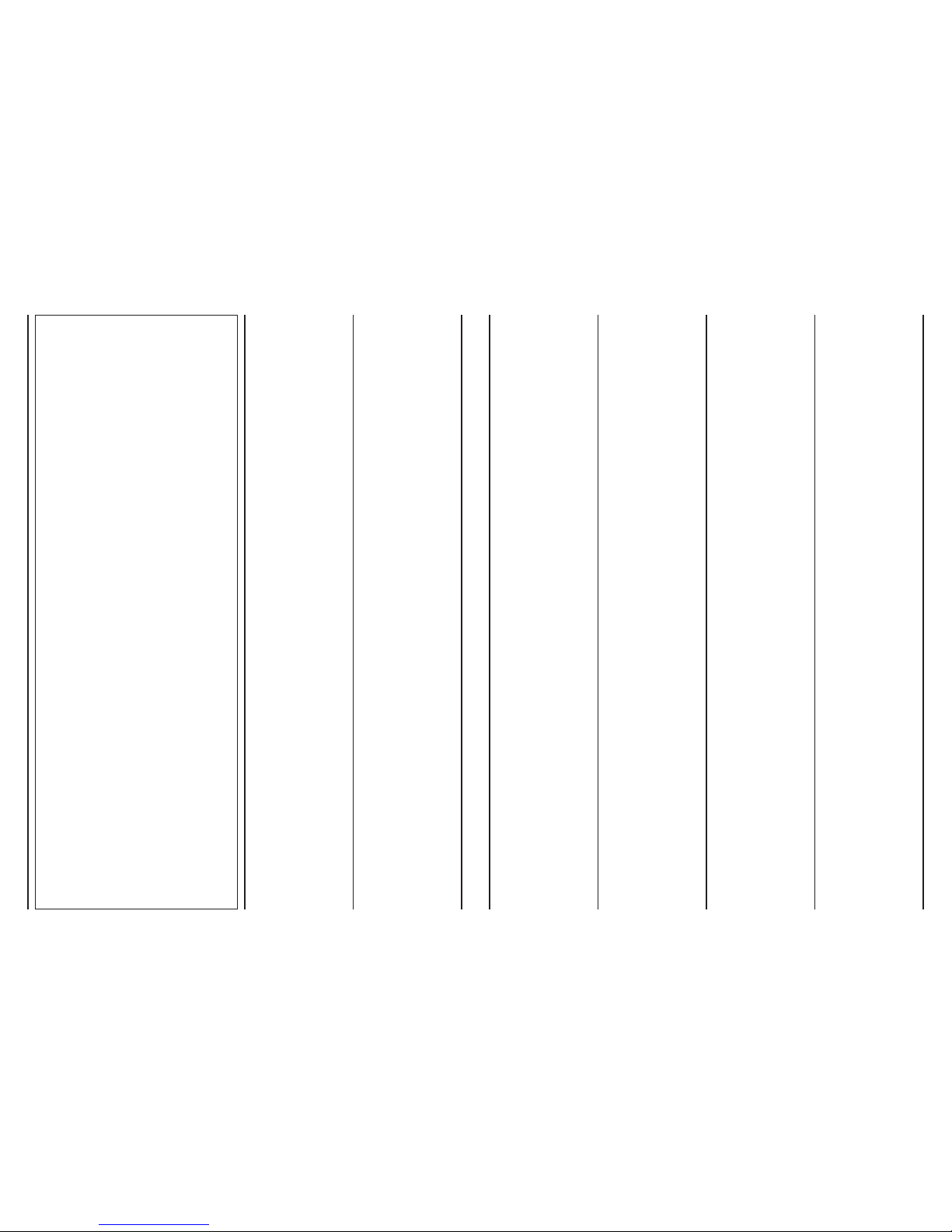
- bien respecter la position
des couleurs aux points
de départ et arrivée
du raccordement;
- quand le câblage est
terminé vérifier visuellement
et physiquement que
les câbles sont en bon état
et bien placés;
- installer les câbles et
les unités de façon à éviter
toute possibilité de contacts
accidentels avec d’autres
câbles de puissance
ou potentiellement dangereux
tels que les câbles
de l’installation d’éclairage;
- ne pas poser les câbles
d’alimentation à 12 volts et
de communication près
des barres de puissances,
lampes d’éclairage, antennes,
transformateurs ou tuyauterie
d’eau chaude ou vapeur;
- ne jamais faire passer
les câbles de communication
dans une goulotte, tuyau,
boîte de dérivation ou
tout autre conteneur avec
les câbles de puissance
ou de l’éclairage;
- séparer les câbles
de communication de tout autre
câble électrique;
- les câbles de communication
et les unités doivent être placés
à 2 mètres au moins des
unités ayant avec de fortes
charges inductives (tableaux
de distribution, moteurs,
générateurs pour systèmes
d’éclairage).
- při dotahování spojení
kabelu ve svorkovnicích nikdy
nepoužívejte příliš velkou sílu.
Při odizolování konce
kabelů postupujte obezřetně.
Nedrťte kabely a zacházejte
s nimi obezřetně;
- vždy respektujte barevné
značení vodičů v kabelu;
- po zkompletování kabeláže
proveďte vizuální i fyzickou
kontrolu kompletnosti,
správnosti zapojení a kvality
provedení prací;
- instalace kazetových jednotek
a kabeláže v jednom kroku je
cesta, jak se vyhnout možným
kolizím s napájecími, nebo
potenciálně nebezpečnými,
kabely nebo s kabely určenými
pro osvětlení;
- neumísťujte trasy vedení
pro 12V napájecí kabeláž
a kabeláž pro komunikační
kabely v blízkosti napájecích
zdrojů, světel, antén,
transformátorů nebo
horkovodního či parního potrubí;
- nikdy neumísťujte komunikační
kabeláž ve stejném žlabu,
trubce, rozvodné krabici nebo
v rozvaděči spolu s napájecími
kabely nebo s kabeláží
pro osvětlení;
- vždy se ujistěte, že kabeláž
pro komunikaci je v dostatečné
vzdálenosti od ostatních
elektrických kabelů;
- kabeláž pro komunikaci,
stejně jako vlastní kazetovou
jednotku, neumísťujte ve
vzdálenosti menší než 2 metry
od zařízení, které mohou
produkovat významné
indukované napětí (např.
rozvaděče, motory, měniče
pro osvětlovací systémy atd.).
- no apriete demasiado
los conductores bajo las bornas
de conexión terminal. Pele
la parte terminal del cable
con precaución. No aplaste
el cable que esté en contacto
con sujetacables o soportes
de seguridad;
- respete siempre la posición
de los colores correspondientes
a los puntos de partida
y de llegada de la conexión;
- una vez realizado
el cableado verifique
visualmente y físicamente
que los cables estén bien y
situados correctamente;
- instale los cables y la unidad
de manera que se minimice
la posibilidad de contactos
accidentales con otros cables
de potencia o potencialmente
peligrosos como los cables
de la instalación de iluminación;
- no coloque los cables
de alimentación de 12 volt y
los de comunicación cerca de
la barra de potencia, lámparas
de iluminación, antenas,
transformadores, o tuberías
de agua caliente o vapor;
- no coloque nunca
los cables de comunicación
en ningún conducto, tubo,
caja de derivación, u otro
contenedor, junto con cables
de potencia o de la instalación
de iluminación;
- prevea siempre
una separación adecuada entre
los cables de comunicación
y cualquier otro cable eléctrico;
- mantenga los cables de
comunicación, y las unidades,
a una distancia mínima
de 2 metros de unidad con
pesadas cargas inductivas
(cuadros de distribución,
motores, generadores para
sistemas de iluminación).
-
zet de geleiders niet overdreven
aan in het klemmenbord.
Ontbloot zorgvuldig
het uiteinde van de kabel.
Plet de kabel niet ter hoogte
vanm de kabelhouder
of de veiligheidshouders;
- respecteer altijd de positie
van de kleuren ter hoogte van
de vertrek en aankomstpunten
van de aansluiting;
- controleer na de bekabeling
visueel en fysiek of de kabels
in goede staat verkeren
en correct geplaatst zijn;
- installeer de kabels
en eenheden op dergelijke
wijze dan een mogelijk contact
met andere vermogenskabels
of potentieel gevaarlijke kabels,
zoals die van de verlichting,
zoveel mogelijk beperkt wordt;
- plaats de voedingskabels
van 12 volt en de
communicatiekabels niet vlakbij
vermogensstaven,
verlichtingstoestellen, antennes,
transformatoren of
warmwater- en stoomleidingen;
- plaats de communicatiekabels
nooit in een kabelgoot, buis,
aftakdoos of andre houder
samen met vermogenskabels
of kabels van de
verlichtingsinstallatie;
- zorg ervoor dat
de communicatiekabels en
alle andere elektrische kabels
altijd goed gescheiden zijn;
- bewaar altijd een afstand
van minstens 2 meter tussen
de communicatiekabels en
eenheden met zware inductie-
ladingen (verdeel-kasten,
motoren, generatoren voor
verlichtingssystemen).
- non serrare eccessivamente
i conduttori sotto i morsetti
di collegamento terminale.
Spelare la parte terminale
del cavo con cura e attenzione.
Non schiacciare il cavo in
corrispondenza di pressatravi
o supporti di sicurezza;
- rispettare sempre la posizione
dei colori in corrispondenza
dei punti di partenza ed arrivo
del collegamento;
- una volta effettuato
il cablaggio, verificare
visivamente e fisicamente
che i cavi siano sani
e correttamente disposti;
- installare i cavi e le unità
in maniera da minimizzare
la possibilità di contatti
accidentali con altri cavi
di potenza o potenzialmente
pericolosi quali i cavi
dell’impianto di illuminazione;
- non posare i cavi
di alimentazione a 12 Volt
e di comunicazione vicino
a barre di potenza, lampade
di illuminazione, antenne,
trasformatori, o tubazioni
ad acqua calda o vapore;
- non posizionare mai
i cavi di comunicazione in
alcuna canalina, tubo, scatola
di derivazione, od altro
contenitore, assieme a cavi
di potenza o dell’impianto
di illuminazione;
- prevedere sempre
un’adeguata separazione
fra i cavi di comunicazione ed
ogni altro cavo elettrico;
- tenere i cavi di comunicazione,
e le unità, distanti
almeno 2 metri da unità
con pesanti carichi induttivi
(quadri di distribuzione,
motori, generatori per sistemi
di illuminazione).
- do not excessively tighten
the wires under the connection
terminals. Strip the end
of the cable with care.
Do not crush the cable
at the cable glands or safety
supports;
- always observe the positions
of the colours corresponding
to the start and end
of the connections;
- once having completed
the wiring, visually
and physically check that the
cables are in good condition
and correctly positioned;
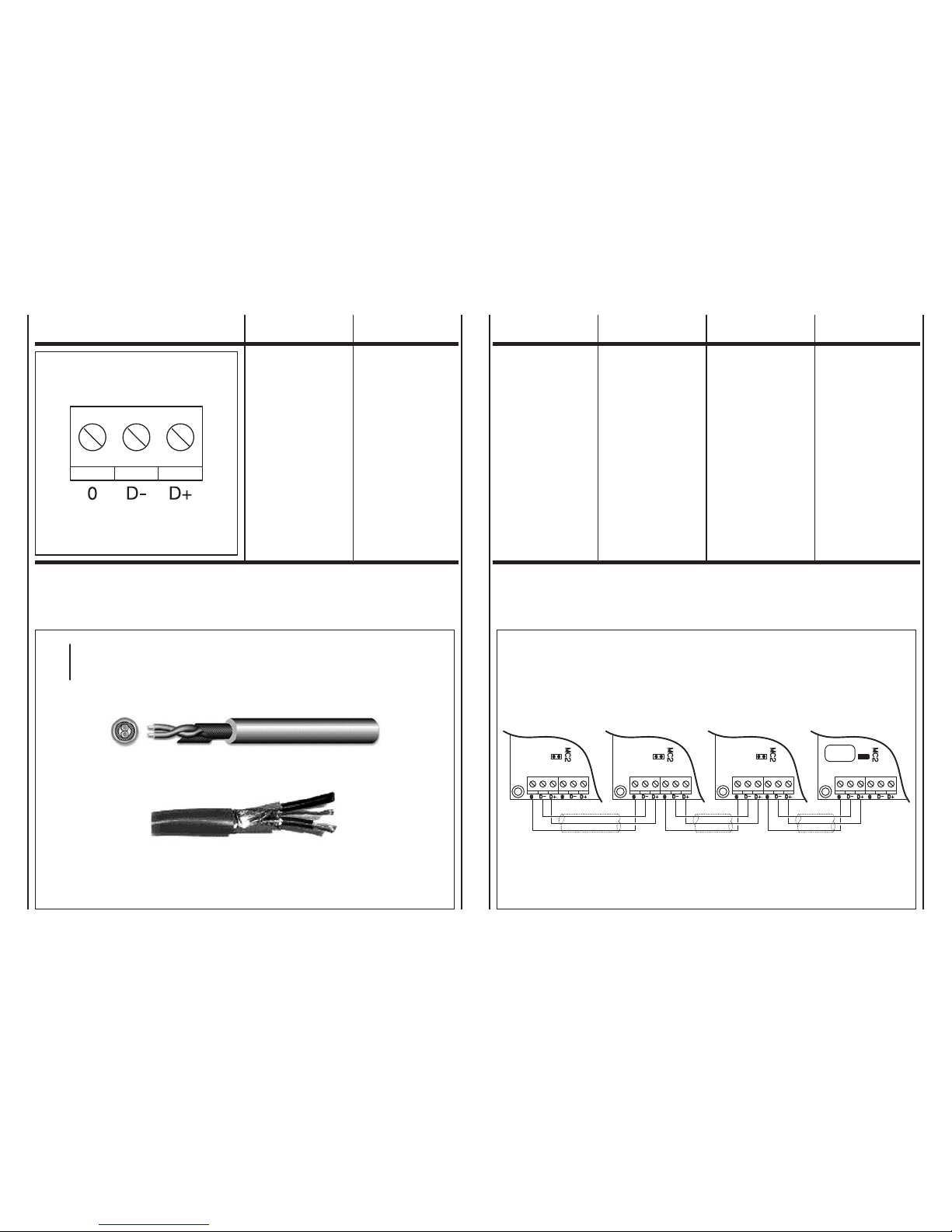
- install the cables and the unit
in such as way as to minimise
the possibility of accidental
contact with other power cables
or potentially dangerous
cables, such as the cables
for the lighting system;
- do not lay the 12 volt power
cables and communication
cables near power devices,
lights, antennae, transformers
or hot water or steam pipes;
- never position
the communication cables
in any conduits, pipes,
junction boxes or other
containers together
with the power cables
or the lighting system cables;
- always ensure there is
adequate separation between
the communication cables
and all other electrical cables;
- keep the communication
cables, and the units
themselves, at least 2 metres
away from appliances
with significant inductive loads
(distribution panels, motors,
generators forlighting systems).
9A9

In fase
di collegamento seriale
degli apparecchi, rispettare
la simbologia di collegamento:
- morsetto “D
-
”
con morsetto “D
-
”
- morsetto “D+”
con morsetto “D+”
- morsetto “0”: collegare
la schermatura del cavo seriale.
NoN iNvertire mai
i collegameNti.
When performing
the serial connection between
the appliances, follow
the connection symbols:
- terminal “D
-
”
with terminal “D
-
”
- terminal “D+”
with terminal “D+”
- terminal “0”: connect
the shield of the serial cable.
Never
reverse the coNNectioNs.
Au moment
du raccordement série
des appareils, respecter
les symboles de raccordement:
- borne “D
-
”
avec borne “D
-
”
- borne “D+”
avec borne “D+”
- borne “0”: brancher
lécran central du câble série.
Ne jamais
iNverser les raccordemeNts.
Když realizujete kabeláž
pro sériovou komunikaci mezi
jednotlivými kazetovými
jednotkami, vždy propojujte
jednotlivé konektory následovně:
- svorku “D
-
”
se svorkou “D
-
”
- svorku “D+”
se svorkou “D+”
- svorku “0”: připoj stínění
sériového komunikačního kabelu.
Nikdy Nepropojujte
kabely „křížem“.
En la fase
de conexión en serie
de los aparatos, respete
la simbología de conexión:
- borne “D
-
”
con borne “D
-
”
- borne “D+”
con borne “D+”
- borne “0”: conectar
el blindaje del cable de serie.
NuNca
iNvierta las coNexioNes.
Bij de seriële aansluiting
van de apparaten,
worden de aansluitsymbolen
gerespecteerd:
- klem “D
-
”
op klem “D
-
”
- klem “D+”
op klem “D+”
- klem “0”: sluit de afscherming
van de seriële kabel aan.
Wissel de aaNsluitiNgeN
Nooit om.
JUMPER
MC2
SlaveSlaveSlaveMaster
10 10A
MESSA A TERRA
DELLA RETE
EARTHING
THE NETWORK
MISE À LA TERRE
DU RÉSEAU
PUESTA A TIERRA
DE LA RED
AARDING
VAN HET NETWERK
Cavo schermato da utilizzare
The shielded cable to be used
Câble blindé à utiliser
Cable blindado que debe usarse
Beschermde kabel te gebruiken
Esempio di collegamento elettrico
Example of electrical connection
Exemple de raccordement électrique
Ejemplo de conexión eléctrica
Voorbeeld van elektrische aansluiting
tipo
type
typ
BELDEN 9841, RS-485, 1x2x24 AWG SFTP, 120 Ohm

Sonda T2 per Change-Over
Solamente sui ventilconvettori in
esecuzione per impianti a due tu-
bi, la commutazione estate/inverno
può avvenire in modo automatico
applicando, sulla tubazione acqua
che alimenta la batteria, la sonda
Change-Over T2 (opzionale). La
sonda va posizionata prima della
valvola a tre vie (non utilizzabile con
la valvola a 2 vie).
In base alla temperatura rilevata
dalla sonda, l’apparecchio si pre-
dispone in funzionamento estivo o
invernale. Nel caso di utilizzo della
sonda T2 in installazioni con unità
Master e Slave, la sonda T2 deve es-
sere montata su tutti gli apparecchi.
A = Tubazione acqua
B = Sonda
C = Isolante anticondensa
Change Over probe T2
Only on the fan coil units designed
for two-pipe systems, the heating/
cooling changeover can be performed
automatically by installing, on the
water pipe supplying the coil, the
Change Over probe T2 (optional).
The probe should be installed before
the three-way valve (not to be used
with 2 way valve).
Based on the temperature measured
by the probe, the appliance will switch
to heating or cooling operation. If
using probe T2 in installations with
Master and Slave units, probe T2
must be fitted on all the appliances.
A = Water pipe
B = Probe
C =
Anti-condensation insulation
Sonde T2 pour Change Over
Seulement sur les ventilo-convecteurs
pour installations à deux tubes, la
commutation été/hiver peut se faire
automatiquement en appliquant,
sur la tuyauterie eau qui alimente la
batterie, la sonde Change Over T2
(option). La sonde doit être placée
avant la vanne à trois voies (non
compatible avec la vanne à 2 voies).
Selon la température relevée par la
sonde, l’appareil se met en fonctionne-
ment été ou hiver. Si on utilise la
sonde T2 dans des installations
avec Unités Maître et Esclaves la
sonde T2 doit être montée sur tous
les appareils.
A = Tuyauterie eau
B = Sonde
C = Isolante anti-condensation
Sonda T2 para Change Over
Sólo en los ventiladores convectores
en realización para instalaciones de
dos tubos, la conmutación verano/
invierno puede suceder de modo
automático aplicando, sobre el con-
ducto de agua que alimenta la ba-
tería, la sonda Change Over T2 (op-
cional). La sonda se coloca antes que
la válvula de tres vías (no se puede
utilizar con la válvula de dos vías).
En base a la temperatura registrada
por la sonda, el aparato se predispone
en funcionamiento verano o invierno.
En caso de que se use la sonda T2
en instalaciones con unidad Master
y Slave, la sonda T2 debe montarse
en todos los aparatos.
A = Conducto de agua
B = Sonda
C = Aislante anticondensación
T2-sonde voor Change Over
Uitsluitend voor de ventilators-convectors
voorzien voor installaties met twee
buizen, kan de omschakeling zomer/
winter automatisch gebeuren door
de sonde Change Over T2 (optie)
te monteren op de waterleiding die de
batterij voedt. De sonde wordt vóór
de driewegskleppen gemonteerd (not
to be used with 2 way valve).
In functie van de temperatuur gemeten
door de sonde, zal het apparaat zich
afstemmen op de zomer- of winter-
werking. Wanneer de T2-sonde
gebruikt wordt in installaties met
eenheden Master en Slave, wordt
de T2-sonde gemonteerd op alle
apparaten.
A = Waterleiding
B = Sonde
C =
Condensvrij isolatiemateriaal
20°C 30°C
Cooling
Refroidissement Heating
Chauffage
Fan only
Ventilation seule
Raffreddamento RiscaldamentoSolo ventilazione
20°C 30°C
Enfriamiento
Afkoeling
Calentamiento
Verwarming
Sólo ventilación
Alleen Ventilatie
Chlazení TopeníPouze ventilátor
A
C
A
B
B
C
V případě, že používáte 2 trubkové zapojení,
lze pro automatické přepínání mezi režimem
topení a chlazení použít čidlo teploty vody
T2 (příplatkové příslušenství). Čidlo musí
být instalována dle obrázku na přívodní
potrubí a to ještě před 3 cestným ventilem
(Je určen pouze pro 2 trubkové zapojení).
Princip funkce je následující. Čidlo T2
měří teplotu přívodního média a elektronika
kazetového fancoilu tuto měřenou hodnotu
vyhodnocuje a podle aktuální teploty sama
automaticky přepíná mezi režimem topení
a chlazení. Pakliže používáte čidlo teploty
vody T2 na instalaci, kde je krom jednotky
Master také více jednotek v zapojení Slave,
je nutné instalovat čidlo teploty vody T2 ve
všech instalovaných kazetových jednotkách.
A =
Potrubí s topnou/chladicí vodou
B =
Čidlo teploty vody T2
C =
Izolace proti kondenzaci
Logica di funzionamento con sonda T2
Operating logic with probe T2
Logique de fonctionnement avec la sonde T2
Funktionslogik mit Fühler T2
Lógica de funcionamiento con sonda T2
Werkingslogica van de sonde T2
11 11A
ACCESSORI ACCESSORIES ACCESSOIRES ACCESORIOS ACCESSOIRES
Sonda T2
tipo: NTC 10K Ohm
(25°C = 10000 Ohm)
Eliminare il connettore
e collegare i due fili
ai morsetti 0 – T2 della scheda.
Probe T2
type: NTC 10K Ohm
(25°C = 10000 Ohm)
Remove the connector
and connect the two wires
to terminals 0 – T2 on the board.
Sonde T2
type: NTC 10K Ohm
(25°C = 10000 Ohm)
Éliminer le connecteur
et raccorder les deux fils
aux bornes 0 – T2 de la carte.
T2
typ: NTC 10K Ohm
(25°C = 10000 Ohm)
Odstraň konektor
a připoj dvě žíly kabelu
ke svorkovnici 0-T2 na kartě
.
Sonda T2
tipo: NTC 10K Ohm
(25°C = 10000 Ohm)
Eliminar el conector
y conectar los dos hilos
a los bornas 0 – T2 de la tarjeta.
Sonde T2
type: NTC 10K Ohm
(25°C = 10000 Ohm)
Elimineer de stekker
en sluit beide draden aan op
de klemmen 0 – T2 van de fiche.

M = Motoventilatore
MB = Scheda elettronica
a infrarossi
AT = Autotrasformatore
C1 = Condensatore
EH = Resistenza elettrica
E = Elettrovalvola
acqua calda e fredda
(impianto a 2 tubi)
E1 = Elettrovalvola
acqua calda
(impianto a 4 tubi)
E2 = Elettrovalvola
acqua fredda
(impianto a 4 tubi)
T1 = Sonda aria
T2 = CHANGE-OVER
T3 = Sonda di minima
COLLEGAMENTI:
GNYE = Giallo/Verde
RD = Rosso = Minima
OG = Arancio = Media
BK = Nero = Massima
BN = Marrone
BU = Blu
WH = Bianco
SCHEMI
DI COLLEGAMENTO
1) Schema di collegamento
impianto a 2 tubi
2) Schema di collegamento
impianto a 4 tubi
3) Schema di collegamento
con resistenza elettrica
M = Fan
MB = Infra-red
electronic board
AT = Autotransformer
C1 = Capacitor
EH = Electrical heater
E = Hot and cold
water valve
(2-pipe system)
E1 = Hot water valve
(4-pipe system)
E2 = Cold water valve
(4-pipe system)
T1 = Air probe
T2 = CHANGE-OVER
T3 = Low temperature
cut-out thermostat
CONNECTIONS:
GNYE = Yellow/Green
RD = Red = Low
OG = Orange = Medium
BK = Black = High
BN = Brown
BU = Dark blue
WH = White
CONNECTION DIAGRAMS
1) Connection diagram
of a 2-pipe system
2) Connection diagram
of a 4-pipe system
3) Connection diagram
with electric resistance coil
M = Motoventilateur
MB = Bornier IR
AT = Autotrasformateur
C1 = Condensateur
EH = Résistance électrique
E = Électrovanne
chaud et froid
(installation 2 tubes)
E1 = Électrovanne chaud
(installation 4 tubes)
E2 = Électrovanne froid
(installation 4 tubes)
T1 = Sonde air
T2 = CHANGE-OVER
T3 = Sonde de temperature
minimum
RACCORDEMENTS:
GNYE = Juane/Vert
RD = Rouge = Mini
OG = Orange = Moyenne
BK = Noir = Maxi
BN = Marron
BU = Bleu foncé
WH = Blanc
SCHEMAS
DE RACCORDEMENT
1) Schéma de connexion
installation à 2 tubes
2) Schéma de connexion
installation à 4 tubes
3) Schéma de connexion
avec résistance électrique
M = Ventilátor
MB = IR elektronická karta
AT = Autotransformátor
C1 = Kondenzátor
EH = Elektrické topné těleso
E = Topný
a chladicí ventil
(2 trubkové zapojení)
E1 = Ventil topení
(4 trubkové zapojení)
E2 = Ventil chlazení
(4 trubkové zapojení)
T1 = Vzduchová sonda
T2 = CHANGE-OVER
T3 = Termostat minimální
teploty
GNYE = Zeleno žlutý
RD =
Červený – minimální otáčky
OG =
Oranžový – střední otáčky
BK = Černý – vysoké otáčky
BN = Hnědý
BU = Tmavě modrý
WH = Bílý
1) Diagram zapojení
pro 2 trubkové systémy
2) Diagram zapojení
pro 4 trubkové systémy
3) Diagram zapojení
pro elektrický ohřev
M = Motoventilador
MB = Tarjeta IR
AT = Autotransformador
C1 = Condensador
EH = Resistencia eléctrica
E = Electroválvula
calentamiento
y enfriamiento
(instalación de 2 tubos)
E1 = Electroválvula
calentamiento
(instalación de 4 tubos)
E2 = Electroválvula
enfriamiento
(instalación de 4 tubos)
T1 = Sonda aire
T2 = CHANGE-OVER
T3 = Sonda de mínima
CONEXIONES:
GNYE = Amarillo/Verde
RD = Rojo = Mínima
OG = Naranja = Media
BK = Negro = Máxima
BN = Marrón
BU = Azul
WH = Blanco
ESQUEMAS
DE CONEXIÓN
1) Esquema de conexión
sistema de 2 tuberías
2) Esquema de conexión
sistema de 4 tuberías
3) Esquema de conexión
con resistencia eléctrica
M = Motorventilator
MB = Schakeling IR
AT = Autotransformator
C1 = Condensator
EH = Elektrische weerstand
E = Elektromagnetische
klep warm en koud
(installatie
met 2 leidingen)
E1 = Elektromagnetische
klep warm (installatie
met 4 leidingen)
E2 = Elektromagnetische
klep koud (installatie
met 4 leidingen)
T1 = Luchtsonde
T2 = CHANGE-OVER
T3 = Uitschakelthermostaat
AANSLUITINGEN:
GNYE = Geel/Groen
RD = Rood = Minima
OG = Oranje = Media
BK = Zwart = Massima
BN = Bruin
BU = Donkerblauw
WH = Wit
AANSLUITSCHEMA’S
1) Verbindingsschema
installatie met 2 leidingen
2) Verbindingsschema
installatie met 4 leidingen
3) Verbindingsschema
met elektrische weerstand
12 12A
LEGENDA LEGEND LÉGENDE LEGENDA LEYENDA LEGENDE

TH2O<30°C
TH2O>20°C
- ESTATE
- SUMMER
- ETE'
- LÉTO
- VERANO
- ZOMER
TH2O<20°C
- INVERNO
- WINTER
- HIVER
- ZIMA
- INVIERNO
- WINTER
- SOLO VENTILAZIONE
- FAN ONLY
- VENTILATION SEULE
- FAN ONLY
- SOLO VENTILACION
- ALLEEN VENTILATIE
TH2O>30°C
CHANGE OVER
JP2
T2T2
WH
T2
BN
MB
4
29
ADDRESS
1 6
4
ON
ON
13 8
6
KD1
35
10
2
CONFIGURATION
57
KD2
DIP N°1 = OFF
230Vac 50Hz
L
4
D0
2
L
N
N
JP7
D0
E
JP8
JP6
PE
3
1
B3
BN
0T2
T1
T2
J8
JP4B
J9
WH
7
F1
F2
B2
BN
JP4A
D-
D+
6
5
JP1
MC1
F1
JP2
0
WH
J1
D-
D+
JP3
T3
F2
M1
T2
WH
BN
B1
OG
BN
J5
WH
RD
BK
OG
M
1
C1
M9
BK
WH
BN
BN
JP5
J6
J4
BK
BU
BK
BU
WH
J3
J7
AT
OG
BK
RD
BN
BU
MB
4
29
ADDRESS
1 6
4
ON
ON
13 8
6
KD1
35
10
2
CONFIGURATION
57
KD2
DIP N°1 = ON
230Vac 50Hz
L
N
PE
B3
BN
0T2
T1
T2
J8
JP4B
J9
WH
7
F1
F2
B2
BN
JP4A
D-
D+
6
5
JP1
MC1
F1
JP2
0
WH
J1
D-
D+
JP3
T3
F2
M1
B1
OG
BN
J5
WH
RD
BK
OG
M
1
C1
M9
BK
WH
BN
BN
JP5
J6
J4
BK
BU
BK
BU
WH
J3
J7
AT
OG
BK
RD
BN
BU
L
4
D0
E2
2
N
JP7
D0
E1
JP8
JP6
3
1
Impianto a 2 tubi / 2 pipe units
Installation à 2 tubes / 2 trubkové zapojení
Instalación a 2 tubos / Installatie met 2 leidingen
Impianto a 4 tubi / 4 pipe units
Installation à 4 tubes / 4 trubkové zapojení
Instalación a 4 tubos / Installatie met 4 leidingen
13 13A
SCHEMI
DI COLLEGAMENTO
cAssette con
Motore Asincrono
A 3 velocità
CONNECTION
DIAGRAMS
cAssette with
three- speed
Asynchronous Motor
SCHEMAS DE
RACCORDEMENT
cAssette Avec
Moteur Asynchrone
à 3 vitesses
kazeTový Fc
s Tří oTáčkovým
asynchronním moTorem
ESQUEMAS
DE CONEXIÓN
cAssette con
Motor Asíncrono
A 3 velocidAd
AANSLUIT-
SCHEMA’S
cAssette Met
Asynchrone Motor
Met 3 snelheden

DIP N°1 = OFF
4
29
ADDRESS
1 6
4
ON
ON
13 8
6
KD1
35
10
2
CONFIGURATION
57
KD2
0
JP4B
7
F1
F2
JP4A
D-
D+
6
5
JP1
MC1
F1
0
WH
RD
J1
D-
D+
JP3
F2
M1
10
JP9
0
M9
J3
BK
BK
WH
RD
GNYE
230Vac 50Hz
L
N
E
PE
BN
BU
BN
BU
0
P+
A+
L
10VDC
0-10Vdc
Input signal
A-
P-
N
P15V
PE
M
3
230V
50Hz
L
4
D0
2
N
JP7
D0
JP8
JP6
3
1
ECM BOARD
POWER
SUPPLY
OG
BN
J5
WH
B1
MB
TH2O<30°C
TH2O>20°C
- ESTATE
- SUMMER
- ETE'
- LÉTO
- VERANO
- ZOMER
TH2O<20°C
- INVERNO
- WINTER
- HIVER
- ZIMA
- INVIERNO
- WINTER
- SOLO VENTILAZIONE
- FAN ONLY
- VENTILATION SEULE
- FAN ONLY
- SOLO VENTILACION
- ALLEEN VENTILATIE
TH2O>30°C
CHANGE OVER
JP2
T2T2
WH
T2
BN
B3
BN
T2
T1
T2
J8J9
WH
B2
BN
JP2
WH
T3
T2
WH
BN
DIP N°1 = ON
4
29
ADDRESS
1 6
4
ON
ON
13 8
6
KD1
35
10
2
CONFIGURATION
57
KD2
B3
BN
0T2
T1
T2
J8
JP4B
J9
WH
7
F1
F2
B2
BN
JP4A
D-
D+
6
5
JP1
MC1
F1
JP2
0
WH
WH
RD
J1
D-
D+
JP3
T3
F2
M1
10
JP9
0
M9
J3
BK
BK
WH
RD
GNYE
230Vac 50Hz
E2
L
N
E1
PE
BN
BU
BN
BU
0
P+
A+
L
10VDC
0-10Vdc
Input signal
A-
P-
N
P15V
PE
M
3
230V
50Hz
L
4
D0
2
N
JP7
D0
JP8
JP6
3
1
ECM BOARD
POWER
SUPPLY
OG
BN
J5
WH
B1
MB
14 14A
SCHEMI
DI COLLEGAMENTO
cAssette con
Motore elettronico
ecM
CONNECTION
DIAGRAMS
cAssette with
ecM
electronic Motor
SCHEMAS DE
RACCORDEMENT
cAssette Avec
Moteur
electronique ecM
kazeTový Fc
s ec moTorem
ESQUEMAS
DE CONEXIÓN
cAssette con
Motor electrónico
ecM
AANSLUIT-
SCHEMA’S
cAssette Met
elektroMotor
ecM
Impianto a 4 tubi / 4 pipe units
Installation à 4 tubes / 4 trubkové zapojení
Instalación a 4 tubos
Installatie met 4 leidingen
Impianto a 2 tubi / 2 pipe units
Installation à 2 tubes / 2 trubkové zapojení
Instalación a 2 tubos
Installatie met 2 leidingen

LOGICA
DI FUNZIONAMENTO
CON RESISTENZA
ELETTRICA
— Accessorio —
OPERATING
LOGIC
WITH ELECTRICAL
HEATER
— Accessory —
LOGIQUE DE
FONCTIONNEMENT
AVEC RESISTANCE
ELECTRIQUE
— Accessoire —
— PříslušensTví —
LÓGICA DE
FUNCIONAMIENTO
CON RESISTENCIA
ELÉCTRICA
— Accesorio —
FUNCTIONERINGS-
LOGICA
MET ELEKTRISCHE
WEERSTAND
— Accessoire —
I ventilconvettori possono essere
forniti con resistenza elettrica mon-
tata e cablata in fabbrica. La resi-
stenza è corredata di termostato di
sicurezza atto a prevenire il surri-
scaldamento dell’apparecchio.
La scheda MB è in grado di ge-
stire il funzionamento della resi-
stenza secondo più modalità che
rispecchiano le diverse situazioni
impiantistiche:
L1 La resistenza viene gestita
come elemento esclusivo di
riscaldamento. È l’equivalen-
te di un impianto a 4 tubi e la
scheda gestisce la valvola per
l’acqua fredda e la resisten-
za per il riscaldamento.
Impostazione DIP
DIP 1 in ON
DIP 6 in ON
DIP 7 in OFF
L2 La resistenza viene gestita
come elemento ad integra-
zione della batteria ad acqua
nel caso di impianto a 2 tubi.
In modalità riscaldamento il
controllo opera su due stadi
di regolazione: il primo attiva
la valvola acqua della batte-
ria, il secondo stadio attiva il
funzionamento della resisten-
za elettrica.
Impostazione DIP
DIP 1 in OFF
DIP 6 in ON
DIP 7 in OFF
L3 La resistenza viene gestita
come elemento riscaldante
ove risulti che la temperatu-
ra dell’acqua circolante nella
batteria (impianto a 2 tubi)
non sia sufficiente a garantire
la funzione di riscaldamento.
Il controllore utilizza il senso-
re T2, da fissare sulla tuba-
zione acqua, e in modalità
riscaldamento attiva la valvo-
la acqua se la temperatura
rilevata è superiore a 34°C
oppure la resistenza se la
temperatura rilevata è inferio-
re a 30°C.
Impostazione DIP
DIP 1 in OFF
DIP 6 in ON
DIP 7 in ON
e T2 collegata
Per il corretto funzionamento
del sensore T2 non è possi-
bile utilizzare valvole a 2 vie
che impedirebbero la circola-
zione del fluido caldo.
The fans may be supplied with
electric resistance coil already
mounted and wired at the factory.
The resistance coil is equipped
with safety thermostat intended to
prevent device overheating.
The MB card is able to manage
the operation of the resistance coil
according to different modes reflecting
all different plant situations:
L1
The resistance coil is managed
as unique heating element.
It is equivalent to a 4-pipe
system and the card operates
both the cold water valve and
the heating resistance coil.
DIP Setting
DIP 1 ON
DIP 6 ON
DIP 7 OFF
L2
The resistance coil is managed
as an element integrating
the water battery in the case
of a 2-pipe system. When set
on heating mode the control
operates according to two
adjustment stages: the first
activates the water valve of the
battery, the second activates
the the electric resistance
coil.
DIP Setting
DIP 1 OFF
DIP 6 ON
DIP 7 OFF
L3
The resistance coil is managed
as a heating element when it is
detected that the temperature
circulating in the battery
(2-pipe system) is not high
enough to ensure the heating
function. The controller uses
the T2 sensor, to be fixed on
the water piping, and when
the heating mode is on it
activates the water valve if the
temperature detected is higher
than 34°C or it activates the
resistance coil if the temperature
detected is lower than 30°C.
DIP Setting
DIP 1 OFF
DIP 6 ON
DIP 7 ON
and T2 connected
For the correct operation of
the T2 sensor it is not possible
to use 2-way valves that
would prevent the circulation
of the hot fluid.
Les ventilo.-convecteurs peuvent
être fournis avec des résistances
électriques montées et câblée à
l’usine. La résistance est fournie
d’un thermostat de sécurité apte à
prévenir la surchauffe de l’appareil.
La fiche MB est apte à gérer le
fonctionnement de la résistance
selon plusieurs modalités qui
reflètent les différentes situations
de l’installation:
L1
La résistance est gérée comme
élément exclusif de chauffage.
C’est l’équivalent d’une
installation à 4 tubes et la
fiche gère la vanne pour l’eau
froide et la résistance pour
le chauffage.
Réglage DIP
DIP 1 en MARCHE
DIP 6 en MARCHE
DIP 7 en ARRÊT
L2
La résistance est gérée comme
élément à intégration de la
batterie à eau dans le cas
d’installation à 2 tubes. En
modalité de chauffage le
contrôle fonctionne sur deux
étapes de réglage le premier
active la vanne d’eau de la
batterie le second stade
active le fonctionnement de
la résistance électrique.
Réglage DIP
DIP 1 en ARRÊT
DIP 6 en MARCHE
DIP 7 en ARRÊT
L3
La résistance est gérée comme
élément chauffant où il résulte
que la température de l’eau
circulant dans la batterie
(installation à 2 tubes) n’est
pas suffisante à garantir la
fonction de chauffage. Le
contrôleur utilise le capteur
T2, à fixer sur la tuyauterie
d’eau, et en modalité de
chauffage active la vanne
d’eau si la température relevée
est supérieure à 34°C ou bien
la résistance si la température
détectée est inférieure à 30°C.
Réglage DIP
DIP 1 en ARRÊT
DIP 6 en MARCHE
DIP 7 en MARCHE
et T2 branchée
Pour le bon fonctionnement
du capteur T2 il n’est pas
possible d’utiliser la vanne à
2 voies qui empêcherait la
circulation du fluide chaud.
Fan-coily mohou být dodávány s
elektrickým ohřevem, montovaným
a připojeným již ve výrobě.
MB karta umožňuje ovládat funkci
elektrického ohřevu v různých
provozních režimech podle konkrétní
situace:
L1 Elektrický ohřev je ovládán
jako jediný zdroj tepla, jeho
funkce je ekvivalentní s funkcí
vytápění u 4 trubkových systémů,
MB karta ovládá jak funkci
vodních ventilů pro chlazení,
tak funkci elektrického ohřevu.
DIP 1 ON
DIP 6 ON
DIP 7 OFF
L2 Elektrický ohřev je ovládán
jako zdroj tepla integrovaný
k vodnímu výměníku tepla
u 2 trubkových systémů, v
případě nastavení režimu
topení je v prvním stupni
aktivován vodní ventil výměníku
tepla a ve druhém stupni je
aktivován elektrický ohřev.
DIP 1 OFF
DIP 6 ON
DIP 7 OFF
L3 Elektrický ohřev je ovládán
jako zdroj tepla v v závislosti
na teplotě proudící vody
(u 2
trubkových systémů) v
případě, že teplota vody není
dostatečně vysoká pro zajištění
funkce topení, ovladač využívá
teplotní čidlo T2 připevněné
na trubce přívodní vody, čidlo
T2 v režimu topení aktivuje
vodní ventil (pokud teplota
vody je vyšší než 34° a nebo
aktivuje elektrický ohřev (pokud
teplota vody je nižší než 30°C).
DIP 1 OFF
DIP 6 ON
DIP 7 ON
T2 připojen
Pro zajištění správné funkce
čidla T2 není možné použít
2-cestné ventily, které by
přerušily cirkulaci topné vody.
Los ventiladores pueden ser
proporcionados con resistencia
eléctrica montada y cableada de
fábrica. La resistencia se acompaña
de un termostato de seguridad
para evitar el sobrecalentamiento
del dispositivo.
La placa MB es capaz de gestionar
el funcionamiento de la resistencia
según las situaciones que reflejan
los diferentes sistemas:
L1 La resistencia se gestiona
como elemento único de la
calefacción. Es el equivalente
de un sistema de 4 tubería
y la placa que gestiona la
válvula para el agua fría y la
resistencia para el calor.
Configuración DIP
DIP 1 en ON
DIP 6 en ON
DIP 7 en OFF
L2
La resistencia es gestionada
como una parte integrante de
la batería de agua en el caso
de un sistema de 2 tuberías.
En el modo de calefacción,
el control funciona en dos
niveles de regulación: el
primero activa la válvula del
agua de la batería, el segundo
nivel activa el funcionamiento
de la resistencia eléctrica.
Configuración DIP
DIP 1 en OFF
DIP 6 en ON
DIP 7 en OFF
L3
La resistencia es gestionada
como parte del calentamiento
donde resulte que la tempe-
ratura del agua circulante en
la batería (sistema de 2 tu-
berías) no sea suficiente para
garantizar la función de la
calefacción. El controlador
utiliza el sensor T2, que se
establecerá en la tubería del
agua, y en modo de calefacción
activa la válvula de agua si
la temperatura detectada es
superior a 34°C o bien la
resistencia si la temperatura
detectada es inferior a 30°C.
Configuración DIP
DIP 1 en OFF
DIP 6 en ON
DIP 7 en ON
y T2 conectada
Para el correcto funciona-
miento del sensor T2 no es
posible usar válvulas de 2
vías que impedirían la circu-
lación fluida del calor.
De ventilatorluchtkoelers kunnen met
gemonteerde elektrische weerstand
en in de fabriek bekabeld geleverd
worden. De weerstand is voorzien
van een veiligheidsthermostaat die
de oververhitting van het apparaat
vermijdt.
De kaart MB kan de functionering
van de weerstand aan de hand van
meerdere modussen behorende bij
de verschillende installaties beheren:
L1
De weerstand wordt beheerd
als een verwarmingselement.
Dit komt overeen met een
installatie met 4 leidingen. De
kaart beheert de klep koud
water en de weerstand van
de verwarming.
DIP Instelling
DIP 1 ON
DIP 6 ON
DIP 7 OFF
L2
De weerstand wordt beheerd
als een element dat de water-
batterij in het geval van een
installatie met 2 leidingen
integreert. Tijdens de verwarming
beheert de controle twee
fases: de eerste fase activeert
de waterklep van de batterij,
de tweede fase activeert de
functionering van de elektrische
weerstand.
DIP Instelling
DIP 1 OFF
DIP 6 ON
DIP 7 OFF
L3
De weerstand wordt beheerd
als een verwarmingselement
als de temperatuur van het
circulerende water in de batterij
(installatie met 2 leidingen)
de functie verwarming niet
kan waarborgen. De controller
gebruikt de sensor T2 op de
waterleiding en activeert tijdens
het verwarmen de waterklep
als de gemeten temperatuur
hoger dan 34°C is, of activeert
de weerstand als de gemeten
temperatuur lager dan 30°C is.
DIP Instelling
DIP 1 OFF
DIP 6 ON
DIP 7 ON
en T2 aangesloten
Voor een correcte functionering
van de sensor T2 kunnen
2-wegskleppen niet gebruikt
worden aangezien ze de
circulatie van warme vloeistof
onmogelijk maken.
15 15A

DIP N°1 = ON
DIP N°6 = ON
DIP N°7 = OFF
230Vac 50Hz
L
4
D0
E2
2
L
N
N
JP7
D0
EH
JP8
JP6
PE
3
1
4
29
ADDRESS
1 6
4
ON
ON
13 8
6
KD1
35
10
2
CONFIGURATION
57
KD2
0T2
T1
T2
J8
JP4B
J9
WH
7
F1
F2
B2
BN
JP4A
D-
D+
6
5
JP1
MC1
F1
JP2
0
J1
D-
D+
JP3
T3
F2
M1
MB
B1
OG
BN
J5
WH
RD
BK
OG
M
1
C1
M9
BK
WH
BN
BN
JP5
J6
J4
BK
BU
BK
BU
WH
J3
J7
AT
OG
BK
RD
BN
BU
Impianto a 4 tubi:
4 pipe units:
Installation à 4 tubes:
4 trubkové zapojení:
Instalación a 4 tubos:
Installatie met 4 leidingen:
funzionamento con resistenza elettrica
quale elemento di riscaldamento principale.
N.B.: non è possibile
montare la sonda T3 su Cassette con resistenza elettrica.
operation with electric resistance coil
as main heating element.
N.B.: you can not mount
the T3 probe on Cassette with electric heater.
fonctionnement avec résistance électrique
comme élément de chauffage principal.
N.B.: vous ne pouvez pas monter
la sonde T3 sur Cassette avec la résistance électrique.
N.B.:
funcionamiento con resistencia eléctrica
como parte de la calefacción principal.
N.B.: no se puede montar
la sonda T3 en Cassette con la resistencia eléctrica.
functionering met elektrische weerstand als
hoofdverwarmingselement.
N.B.: u kunt de sonde T3
niet monteren op Cassette met elektrische weerstand.
16 16A
SCHEMI
DI COLLEGAMENTO
CONNECTION
DIAGRAMS
SCHEMAS DE
RACCORDEMENT
ESQUEMAS
DE CONEXIÓN
AANSLUIT-
SCHEMA’S
L1

DIP N°1 = OFF
DIP N°6 = ON
DIP N°7 = OFF
230Vac 50Hz
L
4
D0
E
2
L
N
N
JP7
D0
EH
JP8
JP6
PE
3
1
4
29
ADDRESS
1 6
4
ON
ON
13 8
6
KD1
35
10
2
CONFIGURATION
57
KD2
0T2
T1
T2
J8
JP4B
J9
WH
7
F1
F2
B2
BN
JP4A
D-
D+
6
5
JP1
MC1
F1
JP2
0
J1
D-
D+
JP3
T3
F2
M1
MB
B1
OG
BN
J5
WH
RD
BK
OG
M
1
C1
M9
BK
WH
BN
BN
JP5
J6
J4
BK
BU
BK
BU
WH
J3
J7
AT
OG
BK
RD
BN
BU
Impianto a 2 tubi:
2 pipe units:
Installation à 2 tubes:
2 trubkové zapojení:
Instalación a 2 tubos:
Installatie met 2 leidingen:
funzionamento con resistenza elettrica
quale elemento di integrazione (controllo su 2 gradini).
Attivazione della resistenza.
in funzione del differenziale tra TSET E TAMBIENTE.
N.B.: non è possibile
montare la sonda T3 su Cassette con resistenza elettrica.
operation with electric resistance coil
as integration element (2-phase control).
Activation of the resistance coil
depending on the differential between TSET and TENVIRONMENT.
N.B.: you can not mount
the T3 probe on Cassette with electric heater.
fonctionnement avec résistance électrique
comme élément d’intégration (contrôle sur 2 plages).
Activation de la résistance
en fonction du différentiel entre TSET et TAMBIENTE.
N.B.: vous ne pouvez pas monter
la sonde T3 sur Cassette avec la résistance électrique.
N.B.:
funcionamiento con resistencia eléctrica
como parte integrante (control en 2 niveles).
Activación de la resistencia
en función del diferencial entre TSET y TAMBIENTE.
N.B.: no se puede montar
la sonda T3 en Cassette con la resistencia eléctrica.
functionering met elektrische weerstand
als integratie (controle in 2 fases).
Activering van de weerstand
aan de hand van het differentieel tussen TSET en TOMGEVING.
N.B.: u kunt de sonde T3
niet monteren op Cassette met elektrische weerstand.
17 17A
L2

EH = ON
E = ON
TH2O<30°C
EH = OFF
E = ON
TH2O>34°C
T2 HEATING
INTERFACING
JP2
T2T2
WH
T2
BN
DIP N°1 = OFF
DIP N°6 = ON
DIP N°7 = ON
230Vac 50Hz
L
4
D0
E
2
L
N
N
JP7
D0
EH
JP8
JP6
PE
3
1
4
29
ADDRESS
1 6
4
ON
ON
13 8
6
KD1
35
10
2
CONFIGURATION
57
KD2
0
T1
J8
JP4B
J9
WH
7
F1
F2
B2
BN
JP4A
D-
D+
6
5
JP1
MC1
F1
0
J1
D-
D+
JP3
T3
F2
M1
MB
B1
OG
BN
J5
WH
RD
BK
OG
M
1
C1
M9
BK
WH
BN
BN
JP5
J6
J4
BK
BU
BK
BU
WH
J3
J7
AT
OG
BK
RD
BN
BU
T2 T2
WH
T2
BN
JP2
Impianto a 2 tubi:
2 pipe units:
Installation à 2 tubes:
2 trubkové zapojení:
Instalación a 2 tubos:
Installatie met 2 leidingen:
funzionamento con resistenza elettrica quale elemento di integrazione.
Attivazione della resistenza
in funzione della temperatura acqua - rilevamento da sonda T2.
N.B.: non è possibile
montare la sonda T3 su Cassette con resistenza elettrica.
operation with electric resistance coil as integration element.
Activation of the resistance coil
depending on water temperature - detection through T2 probe.
N.B.: you can not mount
the T3 probe on Cassette with electric heater.
fonctionnement
avec la résistance électrique comme élément d’intégration.
Activation de la résistance
en fonction de la température de l’eau - détection de sonde T2.
N.B.: vous ne pouvez pas monter
la sonde T3 sur Cassette avec la résistance électrique.
N.B.:
funcionamiento con resistencia eléctrica como parte integrante.
Activación de la resistencia
en función de la temperatura del agua – detección del sensor T2.
N.B.: no se puede montar
la sonda T3 en Cassette con la resistencia eléctrica.
functionering met elektrische weerstand als integratie.
Activering van de weerstand
aan de hand van watertemperatuur - meting door meter T2.
N.B.: u kunt de sonde T3
niet monteren op Cassette met elektrische weerstand.
18 18A
L3

Fissare il ricevitore
sulla plafoniera come mostrato
in Figura “1”.
Non si risponde
in caso di danni provocati
da modifiche o manomissioni
dell’apparecchio.
Fasten the receiver
onto the support as shown
in Figure “1”.
No liability is accepted
for damage caused
by modifications to or tampering
with the appliance.
Fixer le récepteur
sur le plafonnier voir fig. “1”.
La société ne répond
pas des dommages causés
par des modifications
ou détériorations de l’appareil.
Přišroubujte infračervený
přijímač k čelní desce podle
obrázku 1.
Výrobce neodpovídá za
škody způsobené upravovaným,
či jinak neodbornými zásahy
poškozeným, zařízením.
Fije el receptor al plafón
como indica la figura “1”.
La empresa no se hace
responsable en caso de daños
provocados por modificaciones
o manipulaciones del aparato.
Bevestig de ontvanger
op het plafondelement, zoals
geïllustreerd in figuur “1”.
De fabrikant kan niet
aansprakelijk worden gesteld
voor schade veroorzaakt door
wijzigingen aangebracht aan
het apparaat.
19 19A
MONTAGGIO
DEL RICEVITORE
SULLA PLAFONIERA
MOUNTING
THE RECEIVER
ON THE SUPPORT
MONTAGE
DU RECEPTEUR
SUR LE SUPPORT
MONTAJE
DEL RECEPTOR
EN EL PLAFÓN
MONTAGE
ONTVANGER OP
PLAFONDELEMENT
MONTAGGIO
DELLA PLAFONIERA
SUL CASSETTE
MOUNTING
THE SUPPORT
ON THE CASSETTE
MONTAGE
DU SUPPORT
SUR LA CASSETTE
MONTAJE
DEL PLAFÓN
EN EL CASSETTE
MONTAGE
PLAFONDELEMENT
OP CASSETTE
Dopo aver installato
l’apparecchio Cassette a soffitto,
seguire i seguenti passaggi
per fissare la plafoniera:
1 - Appoggiare la plafoniera
(dal lato opposto al ricevitore)
al Cassette.
2 - Fissare provvisoriamente
la plafoniera
con l’apposita molla.
3 - Connettere il terminale
del ricevitore al terminale
del cavo proveniente
dalla scheda.
4 - Appoggiare l’intera plafoniera
al Cassette e fissarla
provvisoriamente
con la seconda molla.
5 - Fissare con le apposite viti
la plafoniera al Cassette
(vedi manuale di installazione
e manutenzione Cassette).
After having installed
the Cassette appliance on
the ceiling, proceed as described
below to mount the support:
1 - Rest the support (the side
opposite the receiver)
on the Cassette.
2 - Temporarily fasten
the support using the spring.
3 - Connect the terminal
on the receiver
to the terminal on the cable
running to the board.
4 - Rest the entire support
on the Cassette
and fasten it temporarily
using the second spring.
5 - Fasten the support
to the Cassette using
the special screws
(see the Cassette installation
and maintenance manual).
Après avoir installé
l’appareil Cassette au plafond,
fixer le plafonnier
en procédant comme suit:
1 - Poser le support (du côté
opposé au récepteur)
sur la Cassette.
2 - Fixer provisoirement
le support à l’aide du ressort.
3 - Raccorder la borne
du récepteur à la borne
du câble provenant
de la carte.
4 - Poser tout le support
sur la Cassette et le fixer
provisoirement à l’aide
du deuxième ressort.
5 - A l’aide des vis fournies
fixer le support à la Cassette
(voir manuel installation
et entretien Cassette).
Po instalaci
kazetového fancoilu
do podhledu pokračujte
v instalaci následujícími kroky:
1 - Opřete si čelní desku
kazetového fancoilu
(protilehlou stranou k IR
přijímači) o kazetový fancoil.
2 - Dočasně
si jej přichyťte pružinou.
3 - Připojte konektor
na kabelu od IR přijímače
do konektoru na kabelu
z elektroniky fancoilu.
4 - Přichyťte celou čelní desku
dočasně ke kazetovému
fancoilu pomocí druhé
pružiny.
5 - Připevněte čelní desku ke
kazetovému fancoilu pomocí
speciálních šroubů
(viz návod pro instalaci a
údržbu kazetového fancoilu).
Después de haber instalado
el aparato Cassette en el techo,
realice los siguientes pasos
para fijar el plafón:
1 - Apoye el plafón (por el lado
opuesto al receptor)
sobre el Cassette.
2 - Fije provisionalmente
el plafón con el muelle
correspondiente.
3 - Conecte el terminal
del receptor al terminal
del cable procedente
de la tarjeta.
4 - Apoye toda la plataforma
sobre el cassette
y fíjela provisionalmente
con el segundo muelle.
5 - Fije el plafón al Cassette
mediante los tornillos
correspondientes
(ver manual de instalación y
mantenimiento del Cassette).
Na het apparaat Cassette te hebben
geïnstalleerd aan het plafond,
volg de volgende stappen voor
de montage van het plafondelement:
1 - Breng het plafondelement
(aan de zijde tegenover de
ontvanger) tegen de Cassette.
2 - Bevestig het plafondelement
voorlopig met de daartoe
bestemde veer.
3 - Sluit de klem
van de ontvanger aan op
de klem van de kabel
afkomstig van de fiche.
4 - Breng het volledig plafond-
element tegen de Cassette
en bevestig voorlopig met
behulp van de tweede veer.
5 -
Bevestig het plafondelement
met behulp van de schroeven
aan Cassette (zie handleiding
installatie en onderhoud
Cassette).
Ricevitore
per griglia di ripresa in metallo
(accessorio non incluso).
Receiver
for metal diffuser
(not included accessories).
Récepteur
pour diffuseur métallique
(accessoires non inclus).
IR přijímač
pro kovové čelní desky
(není součástí balení).
Receptor
por rejilla de retención metálica
(accessorios no incluidos).
Ontvanger
voor metalen diffuser
(accessories niet inbegrepen).

20 20A
BATTERIE
Prima di effettuare qualsiasi
operazione con il telecomando,
inserire le batterie a corredo.
Le batterie
che devono essere utilizzate
sono di tipo AAA 1,5 Volt.
BATTERIES
Before performing any operations
with the remote control,
insert the batteries supplied.
Type AAA 1.5 Volt batteries
must be used.
PILES BATERIE BATERÍAS BATTERIJEN
Avant toute opération
avec la télécommande mettre
les piles fournies.
Utiliser des piles
de type AAA 1,5 volt.
Před prvním použitím
infračerveného dálkového
ovladače vložte do dálkového
ovladače přiložené baterie.
Vždy musí být použity
pouze baterie typu AAA 1,5V.
Antes de realizar cualquier ope-
ración con el mando a distancia,
insertar las baterías adjuntas.
Las baterías
que se tienen que usar
son del tipo AAA 1,5 Volt.
Alvorens de afstandsbediening
te gebruiken, worden de
bijgeleverde batterijen geplaatst.
Gebruik batterijen
van het type AAA van 1,5 Volt.
NON DISPERDERE
LE BATTERIE
NELL’AMBIENTE.
UTILIZZARE GLI APPOSITI
CONTENITORI SMALTITORI.
DISPOSE OF THE BATTERIES
PROPERLY, USING
THE PROPER
WASTE CONTAINERS.
NE PAS ABANDONNER
LES PILES DANS LA NATURE,
ET UTILISER
LES CONTENEURS SPÉCIAUX
POUR LA RÉCUPÉRATION
DES DÉCHETS TOXIQUES.
DE BATTERIJEN
NIET IN HET MILIEU
ACHTERLATEN; GEBRUIK
DE SPECIALE AFVALBAKKEN
VOOR DE VERWERKING.
NO ABANDONAR
LAS BATERÍAS
EN EL MEDIO AMBIENTE,
UTILIZAR
LOS CONTENEDORES
ADECUADOS.
Table of contents
Other Sabiana Remote Control manuals