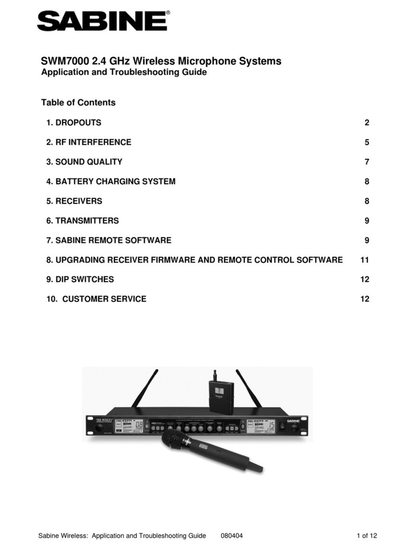
SABINE TRUE MOBILITY WIRELESS SYSTEM SWM3000 User manual

Version 4
OPERATING GUIDE
Every other wireless microphone manual has to warn
users about the perils of feedback with wireless mics.
Welcome to Sabine True Mobility Wireless Systems,
where the only feedback we get is how good it sounds!
WARNING : DON’T WORRY!
Models:
SWM3000
SWM1600


Manufacturer's Name: Sabine, Inc.
Manufacturer's Address: 13301 Highway 441
Alachua, FL 32615 USA
Type of Equipment: Wireless microphone/receiver
Model No.: True Mobility Wireless Systems
Serial No.:
Year of Manufacture: 1999 following
I, the undersigned, hereby declare that the equipment specified above conforms to the above
Directive and Standard.
Place: Alachua, Florida, USA Signature:
Date: January 4, 2002 Full Name: Doran Oster, Sabine President
Declaration of Conformity
DECLARATION OF CONFORMITY
Application of Council Directive: 73/23/EEC and 89/336/EEC
Standards to which conformity is declared:
EN 60065: 1993
EN 60950: 1992
EN 55103-1: 1997
EN 55022: 08:94 + a1:05:05
EN 55103-2: 1997
ETS 300445 (VHF)
ETS 300442 (UHF)

4
Table of Contents
Table of Contents
SECTION ONE : INTRODUCTION ....................................................................... 6
1.1 Using this Operating Guide ........................................................................................... 6
1.2 System Description ........................................................................................................6
1.3 System Features............................................................................................................. 7
SECTION TWO : FRONT & BACK PANEL VIEWS ............................................. 8
2.1 Back Panel View ............................................................................................................. 8
2.2 UHF Front Panel View .................................................................................................... 8
2.3 VHF Front Panel View .................................................................................................... 8
SECTION THREE : SYSTEM COMPONENTS ..................................................... 9
3.1 Handheld Microphone ................................................................................................... 9
3.2 Beltpack Transmitter ......................................................................................................9
3.3 Model Numbers and Accessory Part Numbers............................................................ 9
SECTION FOUR : QUICK SETUP ...................................................................... 10
4.1 Receiver & Transmitter Quick Setup ........................................................................... 10
4.2 FBX Quick Setup ........................................................................................................... 10
SECTION FIVE : RECEIVER & TRANSMITTER SETUP ...................................11
5.1 Multiple Units ................................................................................................................ 11
5.1.1 Number of Simultaneous Systems ..................................................................................................... 11
5.1.2 Antenna Dividers & Extension Antennas ........................................................................................... 11
5.2 Receiver Placement and Connections ....................................................................... 11
5.2.1 Power Cords & Antennas ........................................................................................................................... 11
5.2.2. Receiver Placement.................................................................................................................................... 11
5.2.3 Audio Output Connection........................................................................................................................... 12
5.2.4 Beltpack Headset/Lavalier Microphone connection .................................................................... 13
5.3 Transmitter & Receiver Operating Procedures .......................................................... 13
5.3.1. Start-up Procedures .................................................................................................................................... 13
5.3.2. Transmitter LED Indicators ....................................................................................................................... 14
5.4 Group & Channel Selection ......................................................................................... 15
5.4.1 Selecting Transmitter/Receiver Groups/Channels ....................................................................... 15
5.4.2 Group/Channel Selection (Multiple Receivers/Transmitters) ..................................................... 15
5.5 Audio Output Settings .................................................................................................. 16
5.5.1 Unbalanced Audio Output........................................................................................................................... 16
5.5.2 Balanced Audio Output ................................................................................................................................16
5.6 Transmitter Battery Installation ................................................................................... 16
5.6.1 Battery Usage ................................................................................................................................................ 16
5.6.2 Handheld Microphone (SW30-H, SW16-H) ....................................................................................... 17
5.6.2 Beltpack Transmitters (SW30-TX, SW16-TX) ................................................................................. 17
5.7 Dual Battery Charger ................................................................................................... 18

5
B1-SWM-Op-Guide-v4.pmd 030108-hto
Table of Contents
Sabine True Mobility Wireless Operating Guide Version 4
Models: SWM3000 & SWM1600
© 2003 Sabine, Inc.
SECTION SIX : FBX FEEDBACK EXTERMINATOR ......................................... 19
6.1 Introduction to FBX ...................................................................................................... 19
6.2 Two FBX Advantages................................................................................................... 20
6.2.1 Advantage #1 .................................................................................................................................................... 20
6.2.2. Advantage #2 ................................................................................................................................................... 20
6.3 Who Needs The FBX? .................................................................................................. 21
6.4 FBX Setup & Ready Mode ........................................................................................... 21
6.4.1 FBX Fixed & Dynamic filters ..................................................................................................................... 21
6.4.2 Default FBX filter settings .......................................................................................................................... 22
6.4.3 FBX filter width ................................................................................................................................................ 22
6.5 How To Set Up The FBX Section Of Your True MobilityTM System.......................... 22
6.6 Bypass Button .............................................................................................................. 23
SECTION SEVEN : DE-ESSER SET UP ............................................................ 24
7.1 The Essence of De-essing............................................................................................ 24
7.2 Using the De-esser........................................................................................................ 24
SECTION EIGHT : COMPRESSOR SET UP...................................................... 25
8.1 Basics of Compression ............................................................................................... 25
8.2 Using the Compressor ................................................................................................. 25
8.3 Suggested Compressor Settings ............................................................................... 26
8.3.1 Vocal Compression ...................................................................................................................................... 26
8.3.2 Guitar Compression ..................................................................................................................................... 26
8.3.2 Additional Settings .......................................................................................................................................... 26
8.4 Possible Compression Trouble Areas ........................................................................ 27
SECTION NINE : TIPS AND TROUBLESHOOTING .......................................... 28
9.1 Tips for Maximum Performance of your True Mobility Wireless System ................. 28
9.2 Troubleshooting ...........................................................................................................28
SECTION TEN : MULTIPLE FREQUENCY & USE CHARTS............................. 29
10.1 UHF Frequency Code U922A [USA] ......................................................................... 29
10.2 UHF Frequency Code U808C [Export] .................................................................... 30
10.3 UHF Frequency Code U794A [Export] ..................................................................... 30
10.4 VHF Frequencies [USA] ............................................................................................. 31
10.5 VHF Frequencies [Export] ......................................................................................... 32
SECTION ELEVEN : APPENDICES ................................................................... 33
11.1 FBX Configuration DIP Switch .................................................................................. 33
11.2 Beltpack Transmitter Connector Wiring Diagrams .................................................. 34
11.3 XLR Connector ............................................................................................................ 35
11.4 Beltpack Transmitter Schematic ................................................................................ 35
11.5 Engineering Specifications........................................................................................ 36
SECTION TWELVE : CAUTIONS & WARRANTY .............................................. 38
INDEX ................................................................................................................... 40

6
Section One : Introduction
SECTION ONE : INTRODUCTION
Congratulations on purchasing a Sabine True Mobility™ Wireless System. True Mobility™ Wireless
Systems give you all the built-in processing you need on every microphone.
1.1 Using this Operating Guide
This operating guide covers all Sabine True Mobility™ Wireless Systems — model numbers SWM3000
and SWM1600 — and contains full explanations for everything you need to operate your True Mobil-
ity™ Wireless system.
Section 2 shows front and back panel views for your True Mobility Wireless receiver.
Section 3 lists system components.
Section 4 gives the Quick Setup procedures for Receiver & Transmitter Operation and using the
FBX Feedback Exterminator®. Note that there is also a quick-start label on top of your
True Mobility receiver for the Sabine FBX Feedback Exterminator®, Compressor/Limiter
and De-Esser functions.
Section 5 details receiver and transmitter installation and setup.
Section 6 explains the how and why of Sabine’s FBX technology, and gives a complete understand-
ing of how to set up your FBX filters.
Section 7 details the True Mobility’s De-Esser.
Section 8 explains the use of the Compressor.
Section 9 gives tips on how to get the best performance from your Sabine Wireless, and describes
some possible operating problems and their solutions.
Section 10 has frequency charts for all currently available Sabine Wireless systems.
Section 11 contains information on how to modify your True Mobility’s FBX filters (NOTE: these
procedures are to be performed by qualified personnel only), transmitter wiring
schematics, and engineering specifications for your Sabine Wireless.
Section 12 states caution and warranty information for your True Mobility™ Wireless system.
1.2 System Description
Sabine True Mobility™ Wireless Systems come in UHF and VHF models, with many accessories to
complete your system packages. Both systems include state-of-the-art Phase Locked Loop (PLL)
synthesized transmitter and receivers, True Diversity reception, dual-squelch circuitry, excellent noise
rejection and superior dynamic range. Microphone transmitter configurations consist of handheld,
lavalier, or headset styles. Sabine True Mobility™ Wireless UHF and VHF systems offer optional
front or rear mount antennas, extension antennas, and antenna divider systems.
Sabine Wireless Systems are superior to conventional systems because we include the two most
comprehensive features found in any wireless system: True Mobility and Targeted Input Process-
ing.
We call our system True Mobility because it provides the freedom you should expect from a wireless
system. With a conventional wireless system, your range of movement is limited by the potential for
feedback in acoustical “hot spots.” Some areas are so feedback prone you cannot go near them at all.
Other areas allow only minimal gain before feedback occurs. Until now, freedom from mic cables
meant more likelihood for feedback.
Fortunately, that has changed. Sabine’s True Mobility system includes our patented, industry-stan-
dard FBX Feedback Exterminator®. Your microphones will sound loud and clear without feedback,
and with a greatly increased area of feedback-free movement. This is the freedom you were seeking
when you chose a wireless system.
Sabine’s True Mobility doesn’t stop with automatic feedback control. Conventional wireless systems
require the added cost of outboard equalizers, compressor/limiters, and de-essers to maximize perfor-
mance.

7
B1-SWM-Op-Guide-v4.pmd 030108-hto
Section One : Introduction
Sabine offers a different approach: on-board processing at no extra cost, all dedicated to one
microphone. We call this Targeted Input Processing. With Targeted Input Processing, no mic gets
more processing than it needs, and every mic gets precise, targeted control perfectly suited to provide
optimal performance.
1.3 System Features
All Digital Targeted Input Processing
•Patented FBX Feedback Exterminator®:The industry standard in automatic feedback control.
The True Mobility FBX function includes our fast Turbo Setup Mode, 10 FBX filters, and easy-to- use
controls.
•Auto De-Esser: Sabine’s new automatic de-essing algorithm senses, tracks, and removes sibi-
lance without affecting the rest of your program.
•Compressor: Our famous digital compressor offers the gain management you need to compensate
for all types of performers and speakers, from those who are shy around microphones, to the
boldest worship leader. You can adjust ratio, threshold and attack settings.
True Diversity Receiver
•Phase Locked Loop (PLL): Receiver and transmitter are synthesizer controlled via PLL circuitry.
•Dual-squelch Circuitry: Sabine 2-stage squelch utilizes Tone Key and Noise squelch systems
which eliminate interference and provide quiet, reliable and flexible service.
•Dual-NiMH 9-volt Battery Charger: on-board dual-NiMH 9-volt battery charger means you are
never out of power for handheld transmitters—saves you hundreds of dollars a year in 9-volt battery
costs! Transmitter low-battery warning light lets you know when to change. Sabine’s NiMH batter-
ies give you up to 5 hours of battery life and only MINIMAL MEMORY EFFECT! *
•Radio Frequency (RF) and Audio signal meters: Bright, easy-to-see-and-read level meters
keep you informed of signal strength and audio level.
•User-friendly Channel (and Group for UHF) Selection on Transmitters: The RF signal meter
helps you find a clear frequency.
•Options include: Rear-to-Front Antenna Converter Kit, Antenna Divider Systems, Extension An-
tennas and ExtensionAntenna Boosters (Extension Antenna Booster raises the signal +13 dB and
requires use ofAntenna Divider).
NOTE: MEMORY EFFECT typically occurs when a NiCAD rechargeable battery is recharged
before reaching the end of its initial charge. The battery remembers the charge state prior
to being recharged and uses that as its “empty”charge state. Sabine NiMH batteries are
“memory resistant.”You can recharge your batteries any time you please; whether they
are 1/2, 3/4 or almost fully charged. You will always get consistent battery life from your
Sabine NiMH batteries (for up to 500 charges or more).
*

8
Section Two : Front & Back Panel Views
SECTION TWO : FRONT & BACK PANEL VIEWS
2.1 Back Panel View
Antenna B
Balanced Out
Unbalanced Out
Unbalanced
Output Level Switch DC Power IN
Squelch adjustment
AC Power IN
Antenna A
MIC
LEVEL
ONLY
2.2 UHF Front Panel View
RF Signal
Indicator
Lights
Dual-Battery
Charger
Compartment
Charge
Indicator LEDs FBX Feedback
Exterminator Control
De-Esser Compressor
Gain Reduction
Indicator Lights
Group & Channel
Selectors
Input Level
Indicator
Lights
Output Level
Control
Power &
Power LED
2.3 VHF Front Panel View
RF Signal
Indicator
Lights
Dual-Battery
Charger
Compartment
Charge
Indicator LEDs FBX Feedback
Exterminator Control
De-Esser Compressor
Gain Reduction
Indicator Lights
Channel
Selector
Input Level
Indicator
Lights
Output Level
Control
Power &
Power LED
WARNING:
Do not attempt to recharge alkaline or other
non-rechargeable batteries. Non-rechargeable
batteries will explode if placed in a battery
charger. For best results, use Sabine 7.2-volt
rechargeable batteries (SWABAT).

9
B1-SWM-Op-Guide-v4.pmd 030108-hto
Section Three : System Components
3.3 Model Numbers and Accessory Part Numbers
SWM3000 UHF System
SWM3000-H UHF Handheld Package (SW30-R, SW30-H)
SWM3000-LX UHF Lavalier Package (SW30-R, SW30-TX, SWT42L-4PX)
SWM3000-DX UHF Headset Package (SW30-R, SW30-TX, SWT25W-4PX)
SW30-R 30-Ch Diversity Receiver with Battery Charger
& NiMH rechargeable battery
SW30-H Condenser PLL Hand Held Microphone
SW30-TX PLL Belt Pack Transmitter, 4-pin Mini XLR
SWM1600 VHF System
SWM1600-H VHF Handheld Package (SW16-R, SW16-H)
SWM1600-LX VHF Lavalier Package (SW16-R, SW16-TX, SWT42L-4PX)
SWM1600-DX VHF Headset Package (SW16-R, SW16-TX, SWT25W-4PX)
SW16-R 16-Ch Diversity Receiver with Battery Charger
& NiMH rechargeable battery
SW16-H Condenser PLL Hand Held Microphone
SW16-TX PLL Belt Pack Transmitter, 4-pin Mini XLR
Microphones
SWT42L-4PX Unidirectional Lavalier Microphone, 4-pin Mini XLR
SWT25W-4PX Unidirectional Headset Microphone, 4-pin Mini XLR
SWT30G-4PX Guitar Plug and Cable, 4-pin Mini XLR
Batteries
SWBBAT Rechargeable 7.2-volt NiMH Battery for transmitters
Antenna Accessories
SWA100 TNC Rear to Front Antenna Converter Kit
SWA4V VHF 4-Channel Antenna Divider System
SWAVEXT VHF Extension Antenna (1 set of 2)
SWA4U UHF 4-Channel Antenna Divider System
SWAUEXT UHF Extension Antenna (1 set of 2)
SWAUB UHF Extension Antenna Booster *
SWAEXTM Mounting Bracket for Extension Antenna (1 set of 2)
Mic & Transmitter Accessories
SWC200 Condenser Microphone Capsule Module
SWCCLIP-H Handheld Microphone Holder
SWCTRI Desktop microphone tripod
SWC4P 4-pin connector
SWCCLIP-L Mic clip for SWT42L-4PX Lav Mic
SWCSCR2 Windscreen for Lav Microphones
3.2 Beltpack Transmitter
Extension Antenna Booster requires use of Antenna
Divider.
*
SECTION THREE : SYSTEM COMPONENTS
3.1 Handheld Microphone
NOTE: SWM1600 VHF
microphones and trans-
mitters do not have a
GROUP selector.
Antenna
Power SwitchPower/Battery
LED
Channel Selector
Group Selector Indicates
frequency not
available
Sliding Door
Power
Switch
Low
Battery
Indicator
Mini XLR
Connector
SlotGuitar/Mic Switch
Group Selector*
Channel Selector
Indicates unused frequency
Gain
*NOTE: SWM1600 VHF micro-
phones and transmitters do not
have a Group selector.
NOTE: Use only Sabine 7.2-volt
Rechargeable or 9-volt Alkaline battery

10
Section Four: Quick Setup
4.2 FBX Quick Setup
Please read Section 6.6 How to Set Up the FBX Sec-
tion of your True Mobility System for a complete un-
derstanding of the FBX function and control.
1. Patch the Sabine receiver into your mixer or amp and
position the speakers; then turn on the receiver, trans-
mitter, and microphone. Look for strong RF signal on
the front panel meter; check microphone and adjust
Output Level for strong input level on the mixer or
receiver’s amp.
2. Position the microphone in the primary area of use;
press and hold the Setup button on the receiver until
the Setup indicator flashes 4 times, then release. Do
not use microphone for performance in this mode.
Do not talk into microphone until setup is com-
plete.
3. Slowly raise the gain on the mixer or amp channel
until FBX eliminates the first few feedback tones. Stop
raising gain.
4. Move the microphone to another area of use and slowly
raise gain until FBX eliminates a few more feedback
tones.
5. Repeat step 4 until the Setup indicator automatically
goes off and the Ready indicator comes on.
You may quit Setup mode at any time prior to its
automatic exit by simply pressing the Ready but-
ton.
NOTE : The Bypass button bypasses only the FBX fil-
ters, and not the additional signal processing (de-essing
and compression) available in the Targeted Input Process-
ing section of the Sabine True MobilityTM Wireless Re-
ceiver.
SECTION FOUR : QUICK SETUP
4.1 Receiver & Transmitter Quick Setup
Please read Section Five Receiver & Transmitter
Setupforacompleteunderstandingof how to set upyour
TrueMobilityReceiver.
1. Place the receiver in an open area within visual range
of the intended microphone locations. Note that the
range of your microphones is about 100 meters, but
that structural objects can lessen that range.
2. Turn the Output Level of the receiver and mixer in use
to the minimum setting.
3. Connect the unbalanced output (1/4 inch jack) of your
True Mobility receiver to the unbalanced input of your
mixer or amplifier; or the balanced output (XLR con-
nector) of your receiver to the balanced mic input of
your mixer or amplifier.
NOTE: when putting the unbalanced output of the re-
ceiver into the Line In input jack of a mixer or amplifier,
switch the receiver’s Level Switch to the High position
(see p.10, Fig. 5d). If you connect the unbalanced out-
put of a receiver into the Mic-In input jack of a mixer or
amplifier; switch the receiver’s Level Switch to the Low
position.
4. Turn on Receiver. Set receiver and transmitter to
same Group and Channel. Make sure your trans-
mitter is turned off.
5. Check that the RF Signal LEDs are not lighting up.
If RF Signal LEDs light up before transmitter is turned
on, choose another frequency.
6. Turn on wireless microphone or transmitter. Check that
the REF Signal LEDs are lit.
7. Adjust volume.
a. Speak into the microphone. Adjust the transmitter
Gain until Input Level LEDs (on receiver) light with-
out clipping. NOTE: Step 7.a is for beltpack trans-
mitters only—the Transmitter Gain is not adjust-
able on handheld microphones.
b. Adjust the receiver Output Level to approximately
the 12 o’clock position (or loud enough to supply a
strong input level to the mixer or amplifier).
c. Adjust the volume control of the amplifier and/or
mixer to an appropriate sound level.

11
B1-SWM-Op-Guide-v4.pmd 030108-hto
Section Five: Receiver & Transmitter Setup
CAUTION: Do not use third party receivers or transmitters as part of, or in conjunction with
your Sabine Wireless system. Some third party microphone and pickups can be configured
to work with the Sabine True Mobility. See Appendix 11.2 for wiring diagrams.
Antenna A TNC
Antenna A
AC Power IN
Receiver-side AC
Power cord
Figure 5a - AC Power and Antenna Connections
Figure 5b - DC Power Connections
SECTION FIVE : RECEIVER & TRANSMITTER SETUP
Each Sabine Wireless System consists of a transmitter and a receiver. Sabine’s True Mobility Wireless
receivers are True Diversity receivers—that means they have two fully redundant receivers listening for your
transmitter and trading off automatically to whichever receives the best signal.
5.1 Multiple Units
5.1.1 Number of Simultaneous Systems
UHF receivers/transmitters have 30 frequencies to choose from, but there is a maximum number that can
be used in one location (see Section Ten: Multiple Frequency & Use Charts for more information and
setup). VHF receivers/transmitters have 16 frequencies to choose from. These also have a maximum
number that can be used on one location. UHF and VHF systems can be used together to increase the
number of units. Refer to your receiver Frequency Code and the corresponding information in Section Ten:
Multiple Frequency & Use Charts for how to set up multiple receivers and transmitters.
5.1.2 Antenna Dividers & Extension Antennas
When multiple UHF or VHF systems are in use, a Sabine antenna divider (UHF systems: SWA- 4U; VHF
systems: SWA- 4V) can be used to minimize the number of antennas. Extension antennas can be added to
maintain good reception even when receivers are far from transmitters.
5.2 Receiver Placement and Connections
5.2.1 Power Cords & Antennas
Attach the power cord to the AC Power IN on the back panel and to a 120 - 240-volt AC power source
(alternatively, you may use a 12-15 VDC, 0.6A, 10W power adapter as in Figure 5b). Attach antennas or
antenna connectors to the antenna A & B TNCs on the True Mobility back panel.
5.2.2. Receiver Placement
The receiver should be placed in an open area within visual range of the intended microphone location. Note
that the range of your transmitter is about 100 meters, but that structural objects can lessen that range.
Extension antennas can be added to maintain good reception even when the receiver is located far from the
transmitter.

12
CAUTIONS
- Since the installation of the antennas influ-
ences the operating efficiency of the receiver,
the most important rule is to minimize the dis-
tance between receiving antenna and trans-
mitter for better reception and performance.
- Keep the system away from electrical-noise
sources (electric motors, refrigerators, arc
welders, etc.). Place the receiver at least one
meter above floor level. Keep all transmitters
at least 3 meters away from a receiver an-
tenna.
Your True Mobility receiver can be installed into an EIA standard rack-mount case using the rack-mount
brackets provided. ARear-to-Front Antenna Converter Kit (SWA100) is available to improve reception on
rack-mounted receivers.
5.2.3 Audio Output Connection
Connect the unbalanced output (1/4 inch jack) of your True Mobility receiver to the unbalanced mic input
of your mixer or amplifier; or the balanced output (XLR connector) of your receiver to the balanced mic
input of your mixer or amplifier.
NOTE 1 : The Level Switch af-
fects only the Unbalanced Out-
put on the receiver. In the “Low”
position, the output is the same
as the Balanced (XLR) output.
In the “High”position, the output
is 10 dB higher than the XLR out-
put.
NOTE 2 : Guitar Output: Using ¼-inch jack cable, plug one end into
the receiver’s unbalanced output and the other end to the input of a
guitar amplifier. Switch the Level Switch to the High position.
Section Five: Receiver & Transmitter Setup
*See Section Ten for allowable
distance between transmitter
and receiver.
Figure 5c - Receiver &
Antenna Placement
*
Mixer or Amplifier
Unbalanced Output
Cord (¼-inch)
Balanced
Output Cord
(XLR)
Level Switch
Figure 5d - Audio Output Connection (mic level only)
Balanced Output (XLR)
Unbalanced Output (¼-inch)
MICLEVEL
ONLY

13
B1-SWM-Op-Guide-v4.pmd 030108-hto
Section Five: Receiver & Transmitter Setup
5.2.4 Beltpack Headset/Lavalier Microphone connection
Plug the Headset or Lavalier connector into the 4-pin threaded connector located on top of the UHF of
VHF beltpack transmitter. Be careful to align the notch on the inside of the cord connector with the slot on
the inside of the beltpack connector.
RF Signal LEDs Audio Input LEDs
Figure 5g - Receiver Controls & LEDs
Power On
Indicator light
Figure 5h - Receiver Back Panel Squelch Control
Squelch
MICLEVEL
ONLY
NOTE: See Section 11.2 Beltpack Transmitter
Connector Wiring Diagrams for Sabine True Mo-
bility connector wiring information.
5.3 Transmitter & Receiver Operating Procedures
5.3.1. Start-up Procedures
1. Power up the True Mobility receiver. The red LED on the power switch will indicate power is on.
2. Check RF Signal indicator
LEDs. Other signal sources,
including other wireless com-
munication devices and trans-
mitters, can interfere with the
operation of your receiver. Be-
fore turning on your micro-
phone or beltpack transmitter,
check to see if any of the RF
Signal LEDs on the receiver
are lit. The number of LEDs that light up will indicate the strength of the interference.
NOTE: Some interference can be dealt with using Sabine’s two-stage squelch. Adjust the Squelch
control knob (“SQ”on rear panel of unit) clockwise until all RF Signal LEDs go out.
CAUTION: Increasing the squelch threshold will
shorten the operating distance possible between
microphone and receiver. A much better solution
is to use the Group and Channel selectors to lo-
cate a frequency without interference or with mini-
mal interference.
3. Power up your mixer and or amplifier. Turn volume
controls to the minimum setting.
Power
Switch
Low
Battery
Indicator
Mini XLR
Connector
Slot
2. While gently push-
ing to connect, ro-
tate entire connector
until notches & slots
align, and connector
slides into place.
1. Hold cord-side of the connector
here with index finger and thumb,
and place on top of beltpack recep-
tacles.
3. Lock in place with
screw-on sleeve.
Tighten finger-tight.
Screw-on Sleeve
Figure 5f - Connector Placement

14
Section Five: Receiver & Transmitter Setup
4. Turn on your Sabine Wireless microphone or beltpack transmitter.
Select the same Group/Channel as the receiver (see Section 5.4 Group & Channel Selection).
Under normal circumstances, the RF Signal indicator on the receiver will light up when a transmitter
is turned on within operating range of that receiver.
NOTE: The Sabine Wireless receiver has a two-stage squelch system that allows you to turn on or
off your transmitter while the receiver and sound system are on—without causing pops or clicks
from the Sabine Wireless system.
5. Speak into the microphone. When audio program is added to that RF signal, the Input Level indica-
tors will light up in accordance with the strength of the audio signal. Adjust transmitter Gain to
maximum signal without clipping (NOTE: Handheld microphones do not have gain control).
6. Adjust mixer and amplifier levels.
5.3.2. Transmitter LED Indicators
Sabine True Mobility transmitters incorporate mul-
tifunction LED indicators. These LEDs signify a
variety of information depending on when and for
how long they are lit.
The handheld microphone has an LED next to the
Power Switch (Figure 5i), and one inside the Group/
Channel Selector compartment (Figure 5k). The
Beltpack Transmitter has both LEDs together on
the front control panel.
5.3.2.1 Power/Battery LED. The Power/Battery LED comes on when you first insert the battery
(Handheld Microphone only), and when you first turn the microphone/transmitter on. It stays on for
about two seconds and signifies that the microphone/transmitter is in mute mode during that time. The
LED will then go off automatically, signi-
fying that the microphone/transmitter is
now in active mode. If, after turning on
the microphone/transmitter, the LED
comes on and stays on, this signifies
that the battery is weak and should be
replaced with a Sabine rechargeable bat-
tery from inside the built-in battery com-
partment.
5.3.2.2 Unused Group/Channel LED.
This LED comes on for about two sec-
onds whenever you change a Group/
Channel setting. If the LED stays on,
then the setting you have selected is
not available, and you need to select
another. Please refer to the Group/Chan-
nel chart for your system in Section
Ten.
Figure 5i - Handheld Microphone Power/Battery LED
Power/Battery LED
Figure 5k - Handheld Microphone Channel LED
Unused Group/Channel LED
Figure 5j - Beltpack
Transmitter LEDs
Guitar/Mic Switch
Group Selector*
Channel Selector
Indicates unused frequency
Gain
*NOTE: SWM1600 VHF micro-
phones and transmitters do not
have a Group selector.

15
B1-SWM-Op-Guide-v4.pmd 030108-hto
Section Five: Receiver & Transmitter Setup
Figure 5l - Receiver Group/Channel
Group & Channel
Selectors
Input
Level
LEDs
RF Signal
LEDs
Output
Level
Control
Figure 5n - Beltpack Group/Channel Selectors
NOTE: SWM1600 VHF systems do not have a Group selector
5.4 Group & Channel Selection
Sabine True Mobility UHF Wireless transmitters are
preprogrammed with 30 switchable combinations of
Groups/Channels; True Mobility VHF Wireless trans-
mitters are preprogrammed with 16 switchable Chan-
nels. Both systems allow easy change of transmit-
ter settings.
Change Group/Channel when:
- RF Signal indicator lights flash when you do not have a microphone or transmitter turned on.
- You have several True Mobility Wireless systems operating at once. Each system must operate
at a unique Group and/or Channel setting (see Section Ten).
5.4.1 Selecting Transmitter/Receiver Groups/Channels
1. Turn on the True Mobility receiver —leave transmitter in off position.
2. Check for RF interference. If the RF Signal LEDs are
lighting up, set Group and/or Channel selectors to a
different setting. Repeat this until a clear channel is
located (no RF signal).
3. Using your fingernail or small screwdriver, carefully
set the Group and/or Channel knobs on the transmitter
to the same setting as the receiver (handheld micro-
phone Group and Channel selectors are located inside
the sliding-door compartment above the antenna).
4. Turn on the transmitter and check to see if the RF Signal LEDs light up.
5.4.2 Group/Channel Selection (Multiple Receivers/Transmitters)
SWM3000UHFtransmitters andreceivershavebothGroup andChannelselectorknobs. Thechannels
withineachgrouphavebeenarranged
so that you can use multiple wireless
unitsatasinglelocation,without having
theunits interferewitheachother.Refer
to Section Ten Multiple Use & Fre-
quencyChartsforhowtousemultiple
True Mobility Wireless Systems to-
gether.
NOTE : If you are using only one
Sabine True Mobility Wireless trans-
mitter/receiver, simply select a
group/channel that does not indicate
interference. See Section 5.3, #2 to
determine if there is RF interference
present at your location.
Figure 5m - Handheld Group/Channel Selectors
Channel SelectorGroup Selector
Guitar/Mic Switch
Group Selector*
Channel Selector
Indicates unused frequency
Gain
*NOTE: SWM1600 VHF micro-
phones and transmitters do not
have a Group selector.
Sliding Door
To open: press down firmly
on ridged area with thumb
and slide toward antenna.

16
5.5 Audio Output Settings
5.5.1 Unbalanced Audio Output
Follow these steps to adjust Unbalanced
Audio Output from your True Mobility re-
ceiver (refer to Section 5.2.3. Audio Out-
put Connection for information on bal-
anced/unbalanced audio connection).
1. Switch the Level Switch on the re-
ceiver rear panel to the “Low”position
If you are plugging into a microphone
input on a mixer or amplifier. See Note 1 on page 12 for Level Switch information.
2. Adjust the receiver Output Level knob to the 12 o’clock position (straight up).
3. Adjust the volume control of the amplifier or mixer to an appropriate sound level.
NOTE : The Output Level control on the receiver is used for fine tuning the wireless microphone
output. At the 12 o’clock position, the output level of the wireless microphone is the same as that
of most standard dynamic microphones.
5.5.2 Balanced Audio Output
1. Adjust the receiver Output Level knob to the 12 o’clock position (straight up).
2. Adjust the volume control of the amplifier or mixer to an appropriate sound level.
NOTE: Balanced Output is not affected by the Level Switch setting
5.6 Transmitter Battery Installation
5.6.1 Battery Usage
Sabine True Mobility Wireless handheld microphones and UHF/VHF beltpack transmitters are de-
signed to use common 9-volt transistor batteries. An alkaline 9-volt battery (IEC 6LR61, or equivalent
ANSI and NEDA 1604A) will typically provide 8 hours or more of operation.
Your True Mobility Wireless System comes with a Sabine rechargeable 9-volt size) Nickel Metal
Hydride (NiMH) battery. This battery can be recharged using the built-in battery charger on your
receiver. With a full charge, the typical life of a rechargeable battery is approximately 3 hours or more.
NOTE: Make sure to turn off the microphone/transmitter after use to extend the battery life. Re-
move the battery from the battery compartment if the microphone or transmitter will not be used for
an extended period of time. Rechargeable batteries can be stored in the built-in battery charger on
the receiver, however, the overall battery life (number of times the battery can be recharged) will be
reduced somewhat.
Output Level
Figure 5o - Audio Output
Section Five : Receiver & Transmitter Setup
CAUTION: If the receiver Output Level is set too high, it will cause your sound to be
distorted. Conversely, signal to noise ratio (S/N) will worsen if the receiver Output
Level is adjusted too low.
For more information on getting the most out of your True Mobility system, refer to
Section Nine Tips & Troubleshooting
NOTICE
BATTERIES MUST BE RE-
CYCLED OR DISPOSED
OF PROPERLY
CAUTION
DO NOT BURN OR PUNCTURE BATTERY.
DOING SO COULD RELEASE TOXIC MATE-
RIALS WHICH COULD CAUSE INJURY.
DO NOT SHORT CIRCUIT

17
B1-SWM-Op-Guide-v4.pmd 030108-hto
Push in with
thumb and index
fingers.
Section Five : Receiver & Transmitter Setup
5.6.2 Handheld Microphone (SW30-H, SW16-H)
1. Grip the microphone capsule as shown in Figure 5p. Unscrew the top of the microphone (counter-
clockwise direction).
2. Insert a 9-volt battery into the
battery compartment accord-
ing to the correct polarity as
shown in Figure 5p. Note that
inside the microphone body,
and at the bottom of the bat-
tery cavity, the hole for the
positive contact is larger than
the hole for the negative con-
tact. The moment the battery
touches the terminals inside
the battery compartment, the
On/Battery Indicator will flash briefly. This means the polarity is correct. However, if no flash occurs,
this indicates incorrect insertion, or the battery is dead. Please read Section 5.3.2. Transmitter
LED Indicators for a complete understanding of Sabine multifunction LEDs.
3. Replace cap so that the three contact prongs inside the capsule align with the three silver contact
squares inside the mic body. Tighten capsule finger tight.
CAUTION : Do not force. If the alignment is not correct or the battery is not placed correctly, the
capsule will not close.
5.6.2 Beltpack Transmitters (SW30-TX, SW16-TX)
1. Press in on ribbed areas with thumb and index finger and pull up to open hinged battery door.
2. Note the positive and negative markings on the inside of the battery compartment. Place a 9-volt
battery connector-side first into the battery compartment, making sure the polarity is correct.
3. Push in at ribbed areas and close
door.
NOTE when changing batteries during performance: The Sabine Wireless receiver has a two-
stage squelch system that allows you to turn on or off your transmitter while the receiver and sound
system are on—without causing pops or clicks from the Sabine Wireless system.
Power Switch
Power/Battery LED
Figure 5p - Handheld Microphone Battery Replacement
IMPORTANT
Grip here & turn
counterclockwise
Figure 5q - Beltpack Transmitter Battery Replacement
Note battery
polarity
indicators and
place battery
accordingly. Do
not force.

18
5.7 Dual Battery Charger
The battery charging system incorporates a proprietary built-in intelligent battery charger system on
the receiver. It accommodates either one or two 7.2 volt rechargeable batteries. A red indicator light
means that the charger is in a rapid-charge state.Agreen light means that the batteries have achieved
at least the minimum charge necessary for use, and the charger is in a trickle-charge state. The
green indicator light does not mean that the batteries are fully charged. For full charge, we recom-
mend that batteries be charged overnight.
NOTE 1: Sabine NiMH batteries are shipped in a minimum charge state. We recommend that you
charge your Sabine NiMH battery overnight before using it in a performance.
NOTE 2: As long as your True Mobility receiver is plugged in, batteries inside the charger will be
charged. The receiver power switch does not affect the battery charger.
Section Five : Receiver & Mic Set Up
Figure 5r - Built-in Battery Charger
Squeeze tabs together
and pull out to open.
Tabs
CAUTION: DO NOT INSERT NON-RECHARGEABLE BATTERIES, DAMAGED BAT-
TERIES OR FOREIGN OBJECTS INTO THE BATTERY CHARGER.
Sabine recommends using high-quality Sabine Rechargeable NiMH Batteries (SWBBAT). These bat-
teries are available from your Sabine dealer.
Standard 9-volt batteries also can be used in Sabine Wireless Systems—but do not insert them into
the battery charger!
Sabine NiMH Rechargeable Battery
SWBBAT
++
++
+
Rechargeable
NiMH Battery
7.2v / 160mAh
WARNING:MAY EXPLODE IF DISPOSED OF IN FIRE

19
B1-SWM-Op-Guide-v4.pmd 030108-hto
SECTION SIX : FBX FEEDBACK EXTERMINATOR
6.1 Introduction to FBX
WHY FBX? Feedback is certainly the most embarrassing, most pervasive challenge to the audio
industry. Thepotentialappearanceofsudden,loud,out-of-control feedback is every sound engineer’s
andmusician’snightmare. It disturbs the performer,theaudience,andthe technician; and candamage
equipment and just generally ruin your day.
A typical wireless microphone adds a new level of unpredictability to feedback potential. Feedback
involvesarelationship betweenaspeakerand amicrophone,andthe physicaldistancebetweenthe two
is the principal determinant of feedback. A mic that can move anywhere results in an ever changing
potentialforfeedback.Astepinthe wrong direction may change a clear, loudsoundtoapiercingshriek
in less than a second. The potential for feedback with a wireless system is increased further if lavalier
microphonesareused.Lavaliermicrophonesare placed farther from the mouththanhandheldorhead
setmicrophones,andoftenrequire moregain. Lavaliermicrophones arealsofrequently omnidirectional,
meaning they pick up sound equally from all directions, increasing the chance of feedback due to
increased sensitivity to the sound emanating from the speakers.
The Sabine True MobilityTM solves this problem
by attenuating very narrow bands of feedback-
prone frequencies. The process is automatic,
simple to use, adaptable to changing acousti-
cal conditions and relationships, powerful in its
application, and has minimal consequences to
the audio fidelity of the signal. We call this
automatic filter an FBX Feedback Extermina-
tor®filter, or FBX filter for short.
Before the invention of FBX, the most common
deviceforcontrollingfeedback was the31-band
graphic EQ. However, FBX has three distinct
advantages.Themostobvious is thatFBXfunc-
tions automatically, even during the program.
Another is that FBX micro-filters are precisely
placed anywhere feedback occurs, while EQ
filters are limited to 31 fixed centerpoints. The
difference:FBXfilters do nothavetobe as deep,
so there is more system gain. But the most
importantadvantageisthatFBXmicro-filters are
ten times narrower than 31-band EQ filters.
Using FBX micro-filters will return up to 90
percent of the power removed by EQ filters.
An EQ would need more than 10,000 sliders to
beequivalenttoyourFBX. WithFBXtechnology,
yourmicrophonewillfinallysoundloud enough,
everyone in the audience will understand each
word,andfeedbackwill be farlesslikelytomake
an unwelcome and unexpected visit.
Section SIX : FBX Feedback Exterminator
Figure 6a - Graphic-EQ effect on program
If the graphic EQ really had 1/3 octave filter
widths, the frequency response curve would
vary 6 dB between sliders. This would ruin
the sound.
Graphic EQs usually use one-octave-
wide overlapping filters that provide
much smoother frequency response
curves. Notice that the overlapping fil-
ters add together to cut -16 dB when
the sliders are only pulled down -10 dB.
-10 dB cut at 500, 630,
1K, 1.25K, 1.6K &2K Hz

20
6.2 Two FBX Advantages
TherearetworeasonswhytheTrueMobilityTM
system from Sabine is able to eliminate
feedback while maintaining a high quality
audio signal.
6.2.1 Advantage #1
First, an FBX filter represents a direct hit
on feedback! The FBX targets feedback
withouttakinga bigchunkoutofyour sound.
Tests prove that a single 1/3-octave EQ
slider pulled down 12 dB removes almost
half the power going to the speakers over a
two-octave range. Furthermore, you can’t
place a graphic EQ filter precisely on the
ringing frequency. If you pull down multiple
sliders in a normal setup, you end up with giant frequency holes in your music (see Figure 6b). On the
otherhand,FBXmicro-filtersare 10 times narrower—yougetbackupto90%of the power youlosewith
a graphic EQ! That means more gain before feedback and no loss in sound quality.
EXAMPLE: In Figure 6c, a PA sys-
temwassetup using amicrophone,
mixer, FBX Feedback Extermina-
tor®, power amp and two speakers.
The system’s gain was raised until
the FBX removed nine feedback
points. Next, the FBX was replaced
with a graphic EQ. The EQ was
adjustedwhile the system gain was
raised to the same level achieved
with the FBX. The frequency re-
sponse curves of each device were
then plotted.
Notehow muchmoreoftheprogram
is eliminated using an EQ—whereas only feedback is eliminated using FBX filters.
6.2.2. Advantage #2
ThesecondreasonTrue MobilityTM systems are abletoremovefeedbackwhile maintaining highquality
audiosignalis duetotheplacementof thesignalprocessingin the inputchainofthemicrophone signal.
Many times signal processing (compression and equalization) is placed after the output stage of a
mixer,meaningitisappliedto acombinationof inputsmixedtogetherintooneoutputand passedthrough
the processor. Particularly in the case of equalization and feedback control, one consequence of such
a signal path is that filtering applicable to just one microphone is applied to others in the same mix bus.
In other words, unnecessary filtering (albeit very narrow filtering in the case of an FBX filter) may be
applied to microphones that have different feedback frequencies than some of the filters set.
Placing the filtering and other signal processing in the input signal path is a concept called Targeted
Input Processing. It means each microphone so equipped will have customized, unique signal
processingapplied—andnounneededprocessing.
Sabine True Mobility Wireless Systems give you
- Targetedprocessingforeachmicrophone
- Increasedmobility
- Quiet, fast and easy setup of FBX filters (Our Fastest FBX setup mode!)
Section SIX : FBX Feedback Exterminator
Figure 6c - FBX Filters vs Graphic EQ Filters
Figure 6b - FBX Filters a Direct Hit on Feedback
1/3-octave
EQ filter
Feedback
FBX filter
You get back this
much sound & power
with the FBX!
The grey area
shows you how
much of your
program you
would lose using a
1/3-octave filter to
control feedback
Direct Hit on Feedback!
This manual suits for next models
1
Table of contents
Other SABINE Microphone System manuals
Popular Microphone System manuals by other brands

Nady Systems
Nady Systems ENCORE DUET manual

Pyle Pro
Pyle Pro PDWM1500 operating instructions

American Musical
American Musical ANY SPOT ECMR user manual

PCB Piezotronics
PCB Piezotronics 377 Series Installation and operating manual

Sense
Sense SE-300-WT-HAND manual

Gemini
Gemini GEMINI VHF-1001HL Operation manual