Contacta STS-K064 Operation manual
Speech Transfer Systems
STS-K015, STS-K062, STS-K064, STS-K058
Installation &
User Guide
February 2021

Important Safety Instructions
1. Read these instructions.
2. Keep these instructions.
3. Heed all warnings.
4. Follow all instructions.
5. Do not use this apparatus near water.
6. Clean only with dry cloth.
7. Do not block any ventilation openings. Install in accordance with the
manufacturer’s instructions.
8. Do not install near any heat sources such as radiators, heat risters, stoves, or
other apparatus (including amplifiers) that produce heat.
9. Do not defeat the safety purpose of the polarized or
grounding-type plug. A polarized plug has two blades with one wider than
the other. A grounding type plug has two blades and a third grounding
prong. The wide blade or the third prong are provided for your safety. If
the provided plug does not fit into your outlet, consult an electrician for
replacement of the obsolete outlet.
10. Protect the power cord from being walked on or pinched particularly at
plugs, convenience receptacles, and the point where they exit from the
apparatus.
11. Only use attachments/accessories specified by the manufacturer.
12. Use only with the cart, stand, tripod, bracket, or table specified by the
manufacturer, or sold with the apparatus. When a cart is used, use caution
when moving the cart/apparatus combination to avoid injury from
tip-over.
13. Unplug the apparatus during lightning storms or when unused for long
periods of time.
14. Refer to all qualified service personnel. Servicing is required when the
apparatus has been damaged in any way, such as power-supply cord or plug
is damaged, liquid has been spilled or objects have fallen into the apparatus,
the apparatus has been exposed to rain or moisture, does not operate
normally, or has been dropped.
Safety Precautions
• Ensure that you only use the supplied power supply. Do not
attempt to install your own power supply system otherwise
damage may occur.
• Do not attempt to dismantle or modify any parts of the unit.
No user serviceable fuses or parts are included.
• Ensure the system is not installed in areas of high ambient temperatures or
high levels of humidity or dust.
• It should not be exposed to direct sunlight or be placed next to vibrating or
heat generating equipment.
• This system is designed for indoor use only.
• Do not place the unit on an unstable surface.
• Do not insert liquids or foreign objects. This could result in fire or
electrical shock. If liquids or foreign objects should enter, immediately
turn off the power switch, disconnect the power plug from the power outlet
and contact your local dealer.
• Ensure the aerial is taped down securely. Do not leave any trailing leads that
may cause a trip hazard.
Thank you for purchasing this system. Before using, please read the following
guide to ensure correct usage. After reading, store this guide in a safe place
for future reference. Incorrect handling of this product could possibly result in
personal injury or physical damage. The manufacturer assumes no responsibility
for any damage caused by mishandling that is beyond normal usage defined in
this manual.
If a problem occurs with the equipment, first refer to the Troubleshooting section
of this guide, and run through the suggested checks. If this does not resolve
the problem contact your dealer. They will tell you what warranty condition is
applied.
This symbol is used to alert you to
important instructions within this manual.
This symbol is used to alert you to the
dangers of getting an electric shock.

Contents
Product Overview
Components
Tools Required
Installation Instructions STS-K015
Installation Instructions STS-K062/STS-K064
Installation Instructions STS-K058
Connections
Amplifier Setup
Using the System
Troubleshooting
5
5
6
7
10
15
16
17
19
21
Contacta has a policy of continuous product development, and therefore small specification changes
may not be reflected in this manual. Images, labels, packaging, accessories and product colours are
subject to change without notice.

5
Product Overview
Components
Speech transfer systems provide assistance for clear communication where
normal speech is impaired by use of glass, a security screen or other similar
barriers.
There is also a hearing loop facility included which provides additional assistance
for hearing device wearers.
1. Adhesive Clip x10
2. No.6 x 1/2” Countersunk Screws x15
3. P-Clips x6
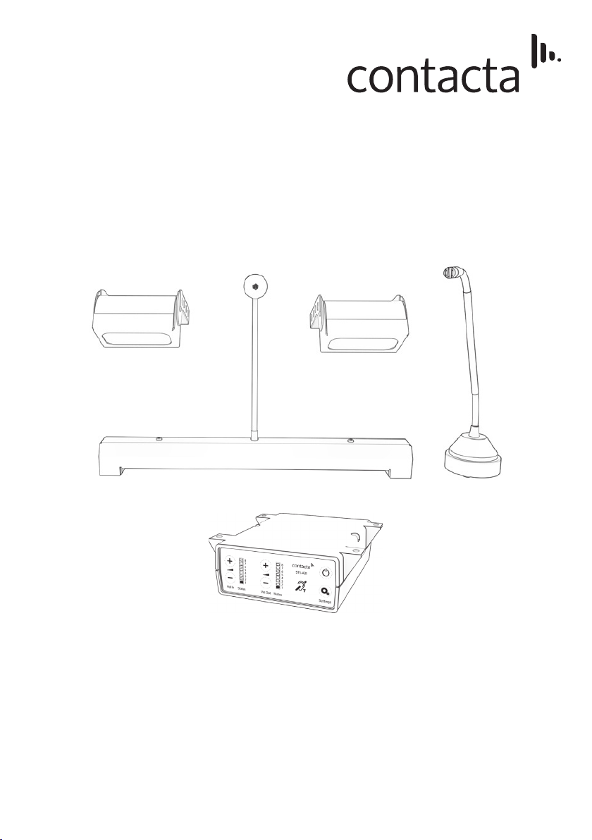
Also included is a Fixing Kit, which contains:
1. Installation and User Manual
2. A31H Amplifier
3. Overhead Speakers (for models
K015 and K062), or a Surface
Mount speaker for model K058.
4. Bent Vandal-Proof Microphone
(for model K058) or a straight
stem Microphone for models K015
and K062
5. Staff Mic Unit (for models K015
and K062) or a Staff Loudspeaker
unit for model K058
6. Hearing Loop Sticker
7. IEC Lead
8. Hearing Loop Aerial
9. Power Supply
10. Mounting Bracket

6
Tools Required
Your basic toolkit will include:
• Screwdrivers (Flat or Blade 2.5mm
and Phillips Head PH2)
• Battery or Mains Drill
• Drillbits: 2mm, 3mm, 5mm and 7mm
• Allen Key Set
• Cable Tacking Gun (10mm)
• Wire Cutters/Strippers
• Pliers
• Tape Measure
• Pencil or Marker Pen
• Torch
• Cable Ties
• Electrical Insulation Tape
• Trunking

7
1. Place the staff microphone on the staff side of the counter top, ensuring that
it does not cause an obstruction and is as close to staff as possible.
2. Place the amplifier under the staff counter, ensuring that it will not obstruct
staff when they are sitting.
3. Mark the 4 fixing points for the amplifier under the counter.
4. Drill and fix the amplifier in place using the supplied screws.
5. Use the cable management hole to run the staff microphone cable back to
the amplifier. If there is not already a cable management hole, one will need
to be drilled in a suitable location near the rear of the counter.
Staff Microphone, Amplifier and Overhead Loudspeakers
Installation Instructions STS-K015
Install the Staff Microphone, Amplifier, Overhead Loudspeakers, Bridge Bar Unit
and Surface Mic in the order described below. If you have followed the steps
closely and the system is not functioning as intended, consult Troubleshooting
on page 21.
Fixing points
8
b. Check the cable route to the amplifier situated under the counter.
Ensure access through the counter top and suitable cable length. Drill
a cable hole through the rear of the counter if neccesary.
c. Mark 2x fixing points to attach the overhead speakers.
d. Drill pilot holes and attach the loudspeaker bracket assembly using
supplied screws.
e. Route the cable from the loudspeaker back to the amplifier in a neat
and tidy fashion, using cable containment where required.
f. Repeat the above steps on the customer side of the counter.
7. Install the power supply close to a power socket outlet using the supplied
mounting bracket and fixing screws.
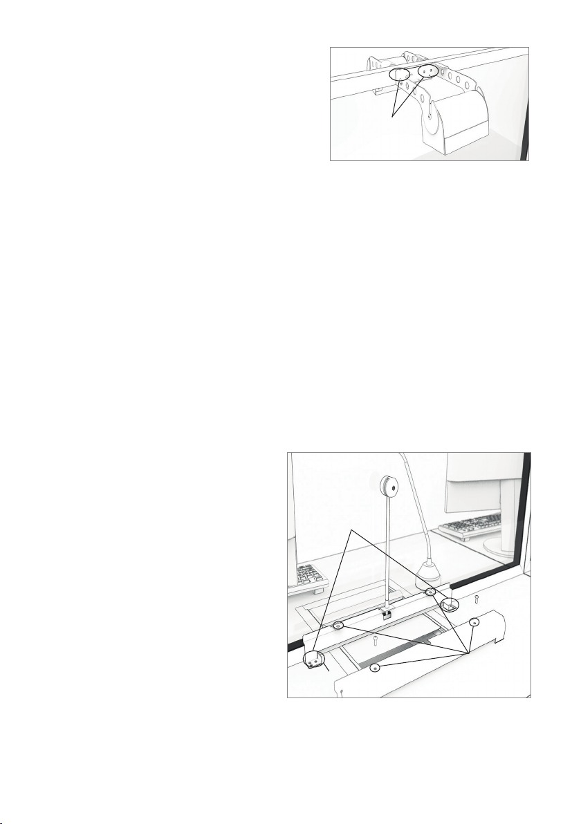
Bridge Bar Unit and Surface Mic
1. Position the bridge bar unit on the
customer side of the counter top
in a central location or around the
pass-through tray if present.
2. Ensure the microphone and
bridge bar are flat against the
screen.
3. Mark the 2 fixing points and 1
cable route hole ready for drilling.
Fixing
points
6. Install the overhead loudspeakers:
a. Find a location on the staff side
directly above the pass-through
tray. Ensure there is sufficient
space and there is no glass behind
where you want to drill.
4. Drill pilot holes and a cable hole
and attach the assembly with the
supplied screws.
5. Feed wiring through the cable hole back to the amplifier. Using provided
fixing holes and screws, attach the bridge bar cover carefully to avoid
damage to wiring.
Fixing
points
Bridge Bar cover
fixing holes
Cable
hole
9
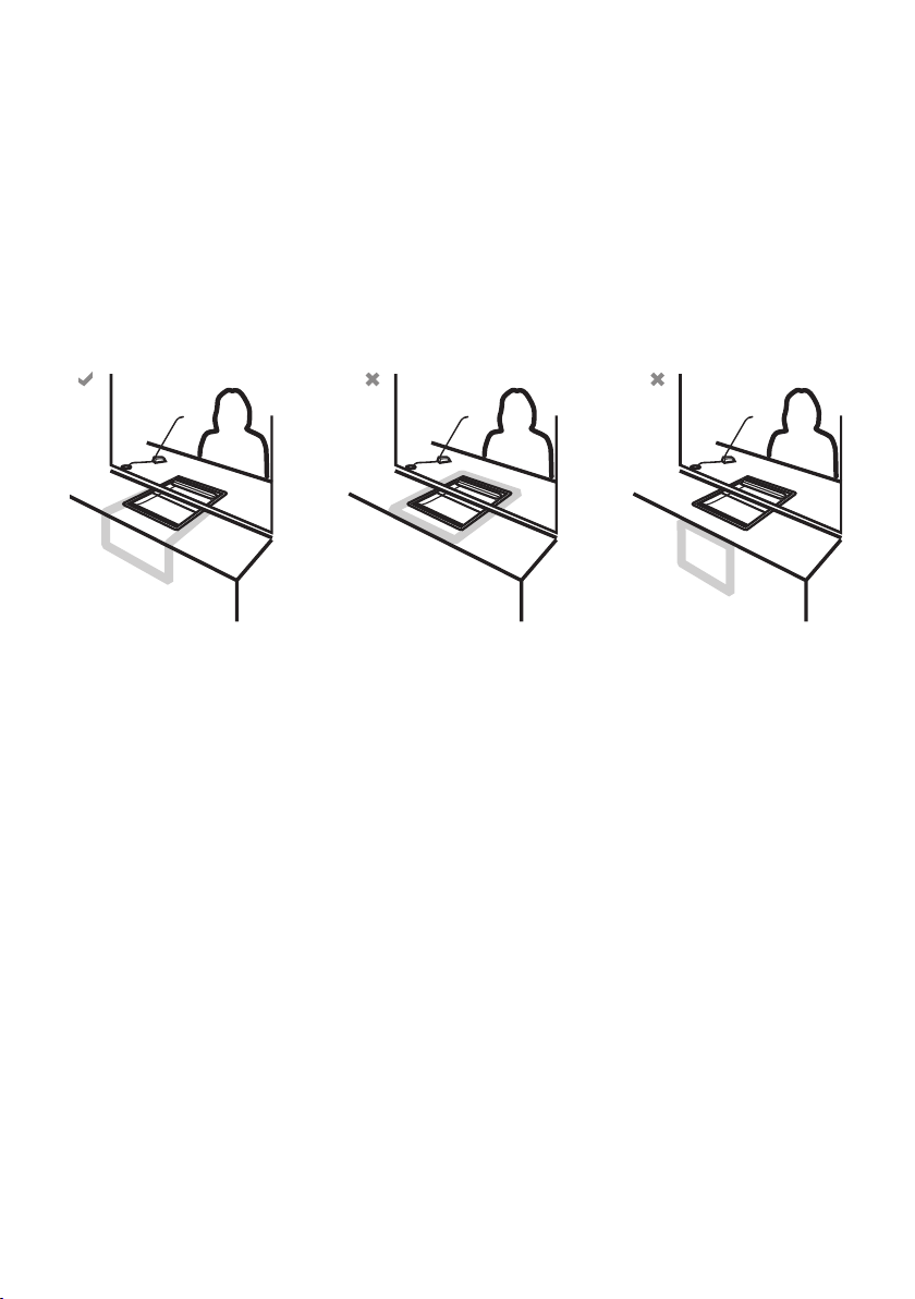
Under-Counter Hearing Loop Aerial Installation
The aerial should be fixed under the desk-top or counter centrally on the
customer side, one half mounted horizontally under the counter and the other
half mounted vertically, facing the customer (as in the first scenario below).
Position the aerial under the counter using either the provided P-clips or another
fixing method of your choice. See the diagram below for recommended
positioning.
Ensure all hearing loop signage is displayed clearly.
XX

10
Installation Instructions K062/K064
Staff Microphone, Amplifier and Overhead Loudspeaker
1. Place the staff microphone on the staff side of the counter/checkout,
ensuring that it does not cause an obstruction and is as close to staff as
possible.
2. Place the amplifier under the staff counter/checkout, ensuring that it will not
obstruct staff when they are sitting.
3. Mark the 4 fixing points for the
amplifier under the counter.
4. Drill and fix the amplifier in place using
the supplied screws.
5. Use the cable management hole to run
the staff microphone cable back to the
amplifier. If there is not already a cable
management hole, one will need to be
drilled in a suitable location near the
rear of the counter/checkout.
6. Install the overhead loudspeakers:
a. Find a location on the staff sidedirectly above the pass-through tray.
Ensure there is sufficient space and there is no glass behind where you
want to drill.
b. Check the cable route to the amplifier situated under the counter/
checkout. Ensure access through the counter/checkout and suitable
cable length.
c. Mark 2x fixing points and 1x cable hole to attach the overhead speakers.
Fixing points
This manual suits for next models
3
Table of contents
Other Contacta Microphone System manuals


