OWI CRS301 User manual

CRS301
INFRARED WIRELESS MICROPHONE SYSTEM
INSTALLATION INSTRUCTIONS

2
This package contains the ff:
A - 1 each . . . . . . . . . .CRS-301-CASE- MIXER/AMPLIFIER
B - 2 each . . . . . . . . . . CRS-IRS - IR SENSORS
C - 1 each . . . . . . . . . . CRS-PMIC - PENDANT MICROPHONE
D - 1 each . . . . . . . . . . CRS-PENCH - PENDANT CHARGER
E - 1 each . . . . . . . . . . CRS-PBAT37- PENDANT MICROPHONE BATTERY
F - 1 each . . . . . . . . . . CRS-LMIC- LAPEL MICROPHONE
G –1 each . . . . . . . . . . MOUNTING PLATE
H – 2 each . . . . . . . . . . CABINET KEYS
Optional Accessories (Sold Separately)
CRS-HHMIC2 - HANDHELD MICROPHONE
CRS-HSMIC - HEADSET MICROPHONE
CRS-HHBAT12 - HANDHELD MICROPHONE BATTERY FOR THE CRS-HHMIC2
CRS-HHCHARGER - CHARGER FOR THE CRSHHMIC2

3
SAFETY INSTRUCTIONS
Read all of these instructions before operating and save instructions for later use.
1. Read Instructions – All the safety and operating instructions should be read before the appliance is operated.
2. Retain Instructions –The safety and operating instructions should be retained for future reference.
3. Heed Warnings –All warnings on the appliance and in the instructions should be adhered to.
4. Follow Instructions –All operating and use instructions should be followed.
5. Water and Moisture –The appliance should not be used near water – for example, near a bathtub, washbowl, kitchen sink, laundry
tub, in a wet basement or near a swimming pool.
6. Carts and Stands –The appliance should be used only with a cart or stand that is recommended by the manufacturer. An appliance
and cart combination should be moved with care. Quick stops, excessive force, and uneven surfaces may cause the appliance and cart
combination to overturn.
7. Wall or Ceiling Mounting –The appliance should be mounted to a wall or ceiling only as recommended by the manufacturer.
8. Ventilation –The appliance should be situated so that its location or position does not interfere with its proper ventilation. For example,
the appliance should not be situated on a bed, sofa, rug, or similar surface that may block the ventilation openings; or, placed in a built-
in installation, such as a bookcase or cabinet that may impede the flow of air through the ventilation openings.
9. Heat –The appliance should be situated away from heat sources such as radiators, heat registers, stoves, or other appliances
(including amplifiers) that produce heat.
10. Power Sources – The appliance should be connected to a power supply only of the type described in the operating instructions or as
marked on the appliance.
11. Grounding or Polarization –Precautions should be taken so that the grounding or polarization means of an appliance is not defeated.
12. Power-Cord Protection – Power-supply cords should be routed so that they are not likely to be walked on or pinched by items placed
upon or against them, paying particular attention to cords at plugs, convenience receptacles, and at the point where they exit from the
appliance.
13. Cleaning –The appliance should be cleaned only as recommended by the manufacturer.
14. Power Lines –An outdoor antenna should be located away from the power lines.
15. Nonuse Periods – The power cord of the appliance should be unplugged from the outlet when left unused for a long period of time.
16. Object and Liquid Entry – Care should be taken so that objects do not fall and liquids are not spilled into the enclosure through
openings.
17. Damage Requiring Service –The appliance should be serviced by qualified service personnel when:
A. The power-supply cord or the plug has been damage; or
B. Objects have fallen, or liquid has spilled into the appliance; or
C.The appliance has been exposed to rain; or
D.The appliance does not appear to operate normally or exhibits a marked change in performance; or
E. The appliance has been dropped or the enclosure damaged.
18. Servicing – The user should not attempt to service the appliance beyond that described in the operating instructions. All other servicing
should be referred to qualified service personnel.

4
INTRODUCTION
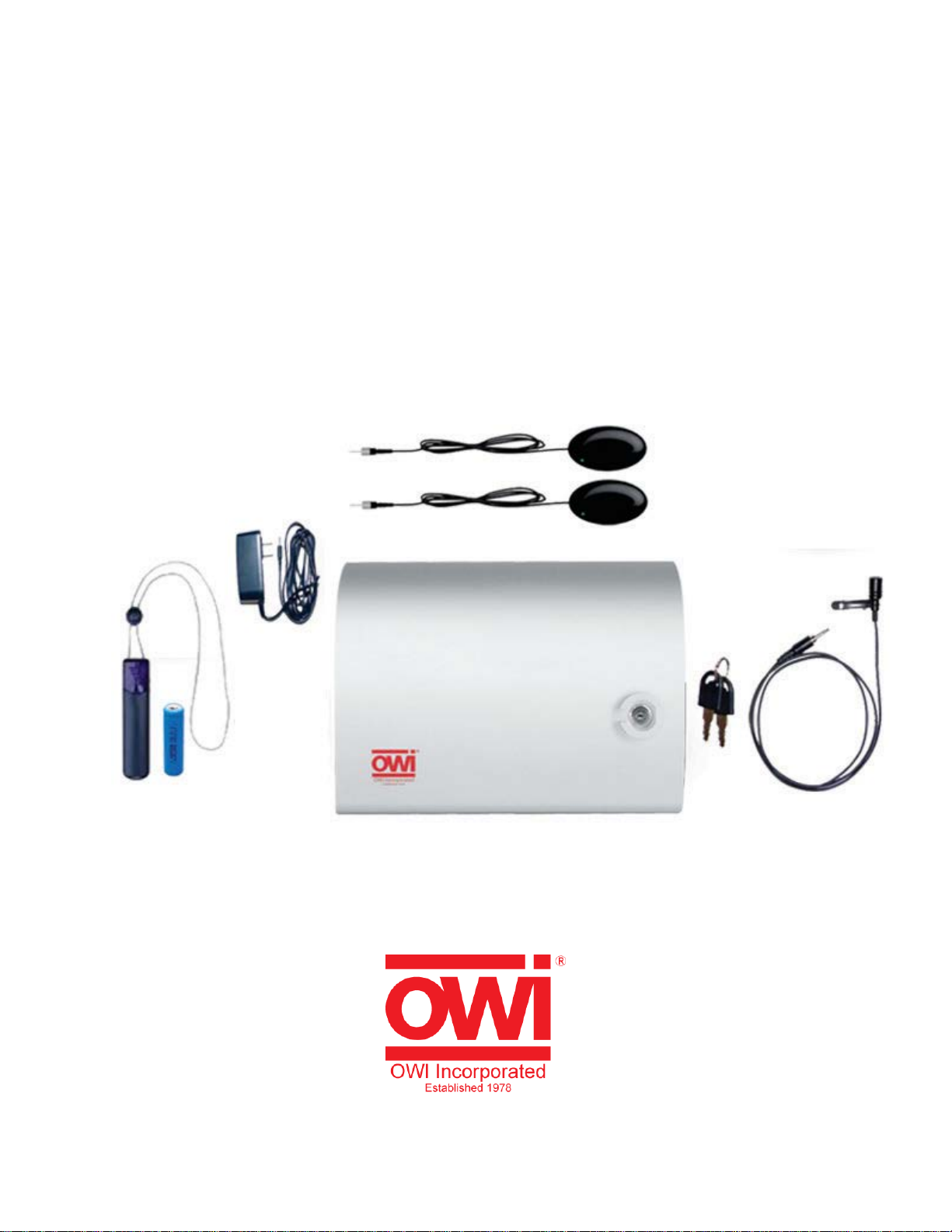
Congratulations and thank you for purchasing the OWI CRS-301 Infrared Wireless Microphone System.
This compact system is suitable for Classrooms, Training rooms, Conference rooms and for Public
speaking.
The CRS System is an Infrared (IR) Wireless system that allows the speaker the freedom to move about
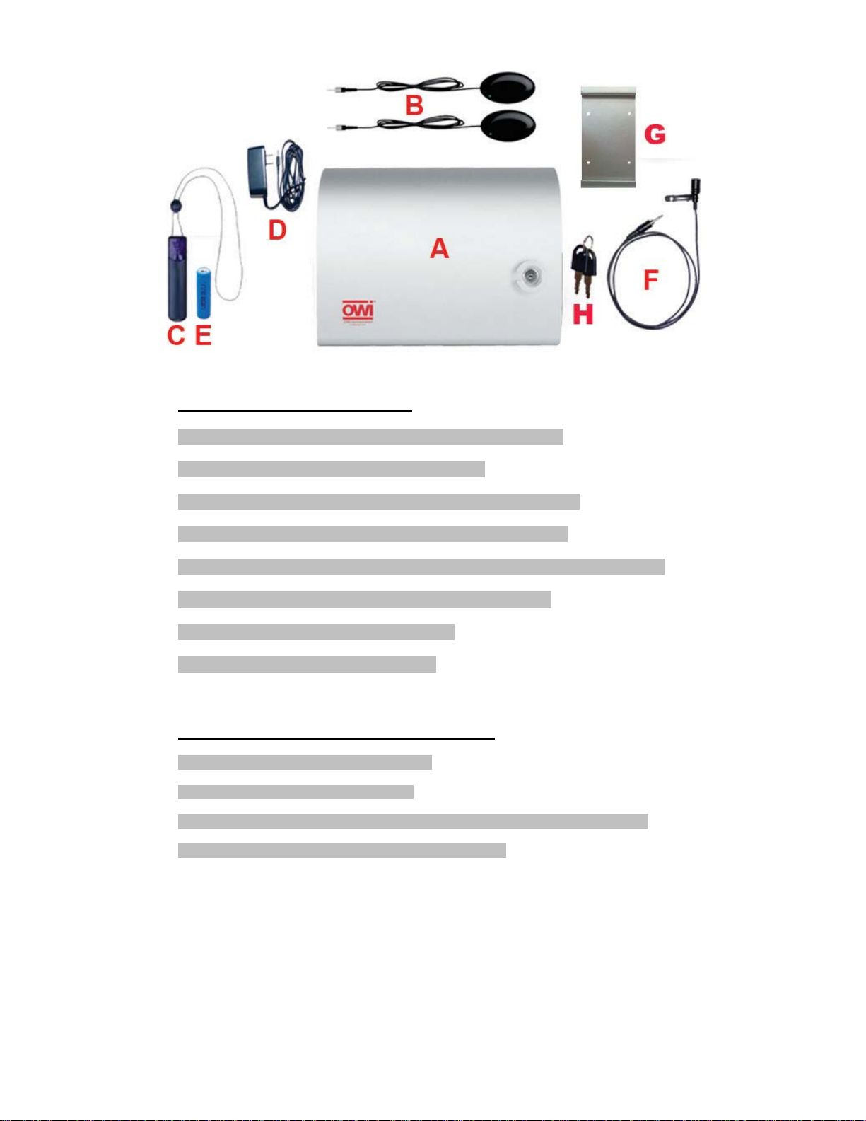
the room without the restriction of a microphone cable. The two included CRS-IRS IR Sensors allow use
of several options of microphones.
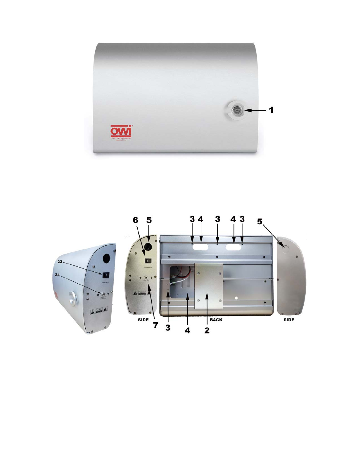
The CRS-301-CASE is an amplified audio mixer that provides inputs for infrared wireless microphones,
two unbalanced 3.5 mini jack in the front, two 3.5 mini jack in the back, and two balanced inputs in the
back (one is for the microphone control). The internal amplifier is a clean, powerful 20 watts per channel
in a dual mono configuration (i.e. the system outputs the same mono signal to up to four speakers).
The CRS-PMIC is a IR Wireless PENDANT MICROPHONE with 2.06 MHz or 2.56 MHz frequency slide
switch under the battery cover.
The CRS-PMIC is a combination IR Wireless PENDANT MICROPHONE AND BATTERY CHARGER. It
gets clipped onto a coat or shirt pocket, or hung around the presenter’s neck on a lanyard and is then
used as a wireless microphone allowing for a hands free presentation.
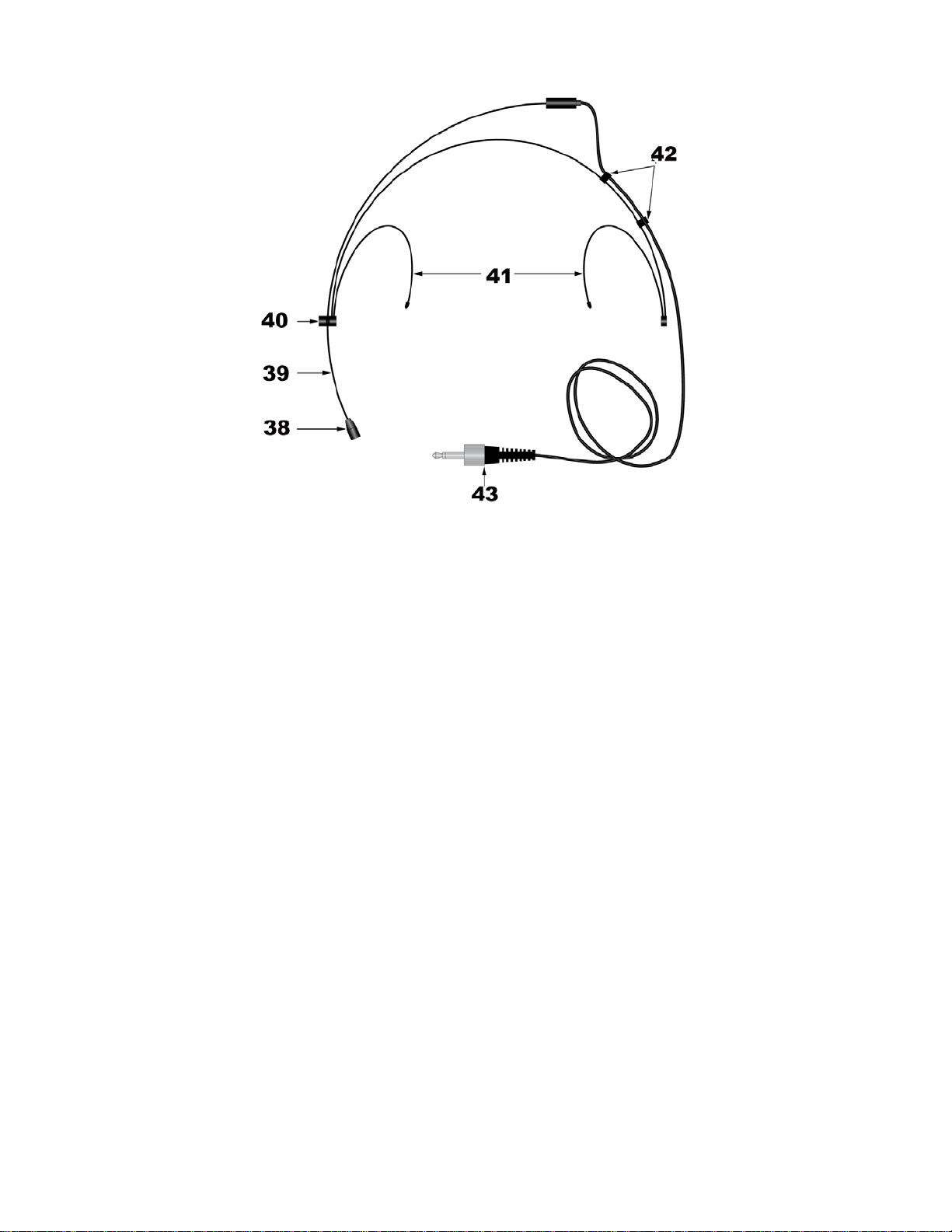
The CRS-PMIC also features a MIC Input that connects to either of the also included CRS-LMIC LAPEL
MICROPHONE or optional CRS-HSMIC HEADSET MICROPHONE. These two ultra-sensitive mics
provide additional options for hands-free presentations.
The CRS-PMIC also features a 3.5 mini-jack stereo input to allow an audio signal to transmit wireless to
the mixer unit.
The IR Wireless Microphones are similar to ‘normal’ mics in how they detect speech, but rather than
directly connecting to a PA or other amplifier, they convert the audio signals into very strong IR pulses
(invisible light pulses) that are ‘seen’ by the IR Sensors. The Sensors receive these pulses and output
electrical pulses to the CRS-301-CASE, where the electrical pulses are converted back to audio signals,
amplified and output to the speakers.
IR is invisible light and IR systems typically require a direct line-of-sight from the transmitter (microphone)
to the receiver (IR Sensors) to operate. The CRS-301 was designed with ultra-high output IR circuitry that
allows the IR pulses output from the microphones to reflect off ceiling, wall and hard floor surfaces. The
IR Sensors are designed to ‘see’ IR from any direction, allowing uninterrupted presentations.
The CRS-HHMIC2 Wireless Microphone (optional) is a HAND-HELD IR WIRELESS MICROPHONE. This
option can be used by the speaker for presentation or can be passed around the classroom or audience
to allow questions to be clearly heard by all.
The CRS-301 System is easy to install and operate. Once set up, it will be ready for class every day. One
important point: Just as students need sleep to re-charge, the microphone batteries need to be kept at
peak performance levels as well, so it is important to re-charge the batteries before each use.
When not in use, the CRS-301-CASE provides a secure, locking door to prevent touching
The CRS-301 when combined with OWI’s P5278 Bookshelf or IC5 or IC6 in-ceiling speakers help create
professional easy to hear presentations of both spoken content and audio from external sources such as
CD/DVD players, Computers, Cable, Satellite, VCR, etc.
OWI CRS-301 Infrared Wireless Microphone System. Always at the head of the class.

5
CRS-301-CASE Features
Figure 1. CRS-301-CASE Front View - Door Closed
1. DOOR LOCK – Locks the CRS-301-CASE Door to keep unauthorized fingers off the system
controls and settings.
CRS-301-CASE CABINET FEATURES
Figure 2. CRS-301-CASE Back and Side Views
2. MOUNTING PLATE – Holds the CRS-301-CASE securely on the wall.
3. MOUNTING KEYHOLES – Five screw keyholes for securing the CRS-301-CASE to a wall or
shelf.
4. WIRE ACCESS –Space in the CRS-301-CASE cabinet allows connection to an external audio
source and two wired microphones, with the door closed.
5. KNOCKOUTS – Two knockouts. Additional wire access on the side of the CRS-301.
6. POWER SWITCH –One, two position toggle switch turns the power mains to the CRS-301-
CASE ON/OFF.
7. POWER INPUT – 15 VOLT, 3.5 AMP POWER INPUT

6
Figure 3. CRS-301-CASE Front Panel (Door Open)
CRS-301-CASE FRONT PANEL FEATURES
The CRS-301-CASE Front Panel features all of the controls for the CRS-301 System.
8. 3.5 Stereo Mini Jack input – on slider 1 (#10)
9. 3.5 Stereo Mini Jack input – on slider 2 (#11)
10. SLIDER VOLUME # 1 – Line Level input control
11. SLIDER VOLUME # 2 – Line Level input control
12. POWER LED INDICATOR LIGHTS
13. SLIDER VOLUME # 3 – Microphone or line level control
14. SLIDER VOLUME # 4 – wireless microphone control
Change Picture to pull down door open

7
Figure 4. CRS-301-CASE Inside Panel
CRS-301-CASE INSIDE PANEL FEATURES
An external audio source such as a CD/DVD Player, computer, projector, cable, satellite, etc and
standard unbalanced, low impedance wired microphones can be connected to the Inside Panel.
15. 3.5 Mini Jack LINE IN – 3.5 Stereo Mini Jack input NOTE: The CRS will output BOTH channels
to BOTH Speakers (mono). Use either channel for a mono source.
16. 3.5 Mini Jack LINE IN – 3.5 Stereo Mini Jack input NOTE: The CRS will output BOTH channels
to BOTH Speakers (mono). Use either channel for a mono source.
17. Balanced input – Mic or Line input
18. Balanced input – Mic or Line input This input is for the microphones
Change Picture to top of new CRS 301
Figure 5. CRS-301-CASE Top Panel
CRS-301-CASE TOP PANEL FEATURES
The IR Sensors and Speakers get connected to the Side Panel
19. SPEAKER TERMINALS – Two pair, five-way binding posts, connect to classroom speakers.
(OWI Models P5278, IC5 or IC6 suggested.)NOTE: Both speakers output the same audio signal,
(mono). The CRS-301 is not a stereo audio system.
20. IR SENSOR JACKS – Three, 3.5mm mini jacks connect to the CRS-IRS IR Sensors for input of
IR pulses (audio signals) from the Headset, Lapel, Pendant or Handheld Microphones. Use
any two of the three inputs with the included IR Sensors
21. LINE OUT - One, 3.5mm mini jack connect to the input of a recording device or another amplifier.
22. WIRE ACCESS –Space in the CRS-301-CASE cabinet allows connection to an external audio
source and two wired microphones, with the door closed..
Figure 6. CRS-301-CASE Side Panel
CRS-301-CASE SIDE PANEL FEATURES
23. DC POWER CORD –One, three prong AC cord connects to a standard 110VAC/60Hz outlet.
Provides AC power to the CRS-301.

8
Figure 7. CRS-IRS IR Sensor
CRS-IRS IR SENSOR FEATURES
24. MINI PLUG – One, 3.5mm mini plug connects to one of the three IR Sensor Jacks on the CRS-
301-CASE Side Panel.
25. CABLE – 50’ cable allows the IR Sensors to be positioned away from the CRS-301-CASE for
optimum coverage for reception of IR pulses from the CRS IR Microphones.
26. ON LED – One, LED illuminates green to indicate that the CRS System is ON and the IR
Sensorsare connected and active.
27. IR SENSOR – Senses the IR pulses output from the CRS IR Microphones. Must be positioned
to have clear ‘line-of-sight’ to the classroom and any location that the CRS Microphones may be
used. The IR Sensor senses IR in an omni-directional pattern (140° off-axis) and will also sense
IR reflected off the ceiling, wall and hard floor surfaces. It has a range of 66 feet.INPUT – One,
Figure 8. CRS-PMIC Pendant Mic/Charger
CRS-PMIC PENDANT MIC/CHARGER FEATURES
The CRS-PMIC Pendant Microphone can be used as a wireless microphone itself or as an IR Transmitter
when used with the Lapel or Headset Mics.
27. MIC INPUT – One, 3.5mm mini jack connects to the mini plug on either the CRS Lapel Mic or
Headset Mic. When either is connected to this jack, it overrides the Pendant Microphone, so
only the Lapel Mic or Headset Mic will be active.
28. CLIP – Clips the Pendant Mic on to the included lanyard or a coat or shirt pocket for use as a
hands free microphone.
29. BATTERY DOOR – Removable battery door for access to the AA re-chargeable Lithium battery.
A regular alkaline battery can be used if necessary, but will not last as long as the Lithium
(approx. 4 hours).
NOTE: THE PENDANT IS ALSO A CHARGER. DO NOT CONNECT THE CHARGER POWER SUPPLY
WHEN USING NON-RECHARGEABLE BATTERIES!

9
30. IR OUTPUT ARRAY – High output IR LED’s output audio as infrared pulses in an omni-
directional pattern that are received by the CRS-IRS IR Sensors. The IR Sensors output
electrical DC pulses to the CRS-301-CASE which converts them back to audio signals, amplifies
them and outputs the audio to the Speakers.
31. MICROPHONE – The Pendant Microphone is located at the top of the Pendant.
32. ON LED – One LED illuminates green to indicate that the microphone is ON.
33. ON/OFF SWITCH – Turns the Pendant ON/OFF.
34. 6V DC IN – One 3.5mm mini jack connects to the included CRS-PENCH Charger Power Supply
for re-charging the Lithium battery. (Charging Time: 3 Hours).
NOTE: THE PENDANT IS ALSO A CHARGER. DO NOT CONNECT THE CHARGER POWER
SUPPLY WHEN USING NON-RECHARGEABLE BATTERIES!
Figure 9. CRS-LMIC Lapel Mic
CRS-LMIC LAPEL MIC FEATURES
The CRS-LMIC Lapel Microphone is used with the Pendant Mic for inconspicuous hands-free
presentations.
35. MICROPHONE – Detects audible sound such as voice. Should be positioned as close to the
speaker’s mouth as possible.
36. LAPEL CLIP – Attaches the Lapel Microphone to a jacket lapel, shirt or blouse.
37. MINI PLUG - Connects to the MIC Input on the CRS-PMIC Pendant. High output IR LED’s on
the Pendant output audio as infrared pulses in an omni-directional pattern that are received by
the CRS-IRS IR Sensors. The IR Sensors electrical DC pulses to the CRS-301-CASE which
converts them back to audio signals, amplifies them and outputs the audio to the Speakers.
NOTE: When connected, the Lapel Mic overrides the Pendant Microphone, so only the Lapel Mic
will be active.

10
Figure 10. CRS-HSMIC Headset Mic (Optional)
CRS-HSMIC HEADSET MIC FEATURES (Optional)
The CRS-HSMIC Lapel Microphone is used with the Pendant Mic and is another option for hands-free
presentations.
NOTE: The CRS-HSMIC is an optional accessory and must be purchased separate from the CRS-301.
38. MICROPHONE – Detects audible sound such as voice. Should be positioned as close to the
speaker’s mouth as possible.
39. MIC BOOM – Adjustable mic boom allows the microphone to be set to the optimum position. The
Boom will extend out from the Headset by carefully pulling the Boom, not the microphone, from
the Boom Hinge. The Boom can also be swiveled into position by carefully turning the Boom at
the Boom Hinge. Push the Wire Clips toward the Boom Hinge to create slack in the wire before
adjusting. Try not to flex or strain the wire connection at the end of the boom more than
necessary to avoid damaging the wire.
40. BOOM HINGE – Allows positioning the microphone as described in Item 38 above.
41. EAR CLIPS – Secures the Headset by wrapping the ear clips around the user’s ears.
42. WIRE CLIPS – Secure the Headset Wires to the Headset.
43. MINI PLUG – Connects to the MIC Input on the CRS-PMIC Pendant. High output IR LED’s on
the Pendant output audio as infrared pulses in an omni-directional pattern that are received by
the CRS-IRS IR Sensors. The IR Sensors output DC electrical pulses to the CRS-301-CASE
which converts them back to audio signals, amplifies them and outputs the audio to the
Speakers.
NOTE: When connected the Headset Mic overrides the Pendant Microphone, so only the Headset
Mic will be active.

11
Figure 11. CRS-HHMIC2 Hand Held Microphone (Optional)
CRS-HHMIC2 HAND HELD MICROPHONE FEATURES (Optional)
The HHMIC2 Hand Held Microphone is an optional accessory that can be used for presentations or can
be passed around the room for Q&A so everyone in the room can clearly hear questions from the class or
audience.
NOTE 1: The CRS-HHMIC2 is an optional accessory and must be purchased separate from the CRS-
301.
NOTE 2: The CRS-HHMCS Charger is also an optional accessory and is purchased separate from both
the CRS-301 and CRS-HHMIC.
44. ON LED – One LED illuminates green to indicate that the microphone is ON.
45. ON/OFF SWITCH – Turns the microphone ON/OFF.
46. IR OUTPUT ARRAY – High output IR LED’s output audio as infrared pulses in an omni-
directional pattern that are received by the CRS-IRS IR Sensors. The IR Sensors output
electrical DC pulses to the CRS-301-CASE which converts them back to audio signals, amplifies
them and outputs the audio to the Speakers.
47. CHARGER CONTACTS –These contacts charge the microphone’s re-chargeable battery when
inserted into the CRS-HHMCS Hand Held Microphone Charger.
NOTE: The CRS-HHMCS Charger is also an optional accessory and is purchased separate from
both the CRS-301 and CRS-HHMIC.

12
Figure 12. Typical Classroom Application
INSTALLATION
CRS-301-CASE
The CRS-301-CASE can be wall or shelf mounted. It should be located in a central location that allows
the IR Sensors to be equally spread in the classroom for optimum visibility to the microphones.
Consideration should also be given to locating the CRS-301-CASE in close proximity to any audio
source that will be connected to the Line In, such as a CD/DVD Player, Projector, Computer, VCR,
Cable, Satellite, etc. It should be installed in a location free from moisture or humidity. The location should
also be easily accessible for operation.
Wall Mount
The CRS-301-CASE comes with a mounting plate that can be screwed on a wood panel wall to hang the
CRS-301-CASE. There are five screw keyholes on the Back Panel (Figure 2) that allow it to be secured
to a wall or cabinet.
HOW TO MOUNT THE CRS201 USING THE MOUNTING PLATE

13

14
Horizontal Mounting
Vertical Mounting
Figure 13. IR Sensor Wall Mount Adaptor
CRS-IRS IR SENSORS
The CRS Microphones output IR Pulses that are invisible light pulses. Ideally, the IR Sensors should be
‘line-of-sight’ to the microphones. The microphones output very strong IR pulses that will reflect off wall,
ceiling and hard floor surfaces and are then ‘seen’ by the sensors which enhances system performance
when a microphone is moving around a classroom. The IR Sensors should be installed on wall surfaces
as high up the wall as possible (in a normal ceiling room) and one should be installed on each side of the
room for best coverage.
1. Attach the Wall-Mount Adaptor to the CRS-IRS as shown in Figure 13.
2. Mount the CRS-IRS as high on the wall as possible, but at least seven feet, so people walking past or
standing in front of the sensor will not block the line-of-sight to the microphones.
3. Pull CRS-IRS Wire to CRS-301-CASE location.

15
Figure 14. Typical CRS System Connections
CONNECTIONS
The CRS-301 System requires only a few simple connections and sets up in minutes. The only required
connections are the IR Sensors, Speakers and Power Cord. Connecting an optional audio source such
as a CD/DVD Player, VCR, Computer, Projector, Cable, Satellite, etc is also simple using standard RCA-
RCA audio patch cables.
IR Sensors
1. Connect the CRS-IRS IR Sensor mini plugs to any two of the three IR Sensor Inputs on the
CRS-301-CASE Top Panel.
Speakers
1. Strip approximately ¼” off each lead and twist the ends so there are no loose strands that can
cause shorts. The recommended speaker wire size is 14 to 16 gauge.
2. Connect to the appropriate + and – Speaker Terminal. Maintain polarity from the speaker.
NOTE: Though the CRS has Left and Right Line Inputs, the Speaker Outputs are mono, so BOTH
channels will be output from BOTH speakers.

16
Line In
1. Connect the left and right line level audio outputs of an audio source to the L and R Inputs
on the CRS-301-CASE using a stereo RCA-RCA patch cable with gold ends.
NOTE: Though the CRS has Left and Right Inputs, the Speaker Outputs are mono, so BOTH
channels will be output from BOTH speakers.
2. Feed the audio patch cable through the Wire Access in the CRS-301-CASE Cabinet to allow
connection with the door closed.
TV/DVD
1. Connect the left and right line level outputs of a TV/Projector or DVD Player using a stereo
male RCA to stereo male ¼” phonoadapter.
NOTE: The TV/DVD Input can be adapted to any line level audio device. Connections may vary
by device.
COMP
1. Connect the line level audio output of a Computer (stereo 3.5mm mini jack typical) using a
stereo male 3.5mm mini plug to stereo male ¼” phonoadapter.
NOTE: The COMP Input can be adapted to any line level audio device. Connections may vary by
device.
AC Power Cord
1. Connect to an unswitched 110V AC outlet.
Figure 15. CRS-301 System Signal Path

17
OPERATION
1. IF TURNING THE SYSTEM ON FOR THE FIRST TIME, turn the VOL Knobs all the way down (full
counterclockwise).
2. With all system connections confirmed, press the Power Switch to turn the system ON.
3. If using the Lapel or Headset Mic, connect to the Pendant as shown in Figure 16. Be sure the
Pendant is pointing toward the IR Sensors so the IR Pulses from the Pendant will be ‘seen’ by the
IR Sensors.
4. Turn the Hand Held Microphone (or Pendant) ON.
5. Set the MAIN VOL Knob on the CRS-301-CASE to 12 o’clock.
6. Slowly raise the WIRELESS VOL level until the output from the Speakers is set to the desired level.
If feedback occurs (audio squeal from the speakers) lower the WIRELESS VOL level or move the
microphone away from the speaker.
7. Repeat Step 6for any audio device(s) connected to LINE IN, TV/DVD and COMP, and adjust the
LINE IN, TV/DVD and COMP levels as needed.
8. Confirm the relative volume of the microphone(s) to the audio device(s) and adjust if necessary.
(The audio from the microphone(s) should be heard above the audio from the device(s) connected
to LINE IN, TV/DVD and COMP.)
9. Adjust the MAIN VOL as appropriate so the microphone(s) and audio device(s) can be clearly
heard throughout the entire room. (Set to the highest comfortable listening level to avoid listener
fatigue.)
10. When finished using the system, turn the microphones OFF and turn the CRS-301-CASE POWER
Switch OFF. Do not change the Volume settings. They will now be set for typical use in that room
and should not need further adjustment.

18
BATTERIES
Be sure to charge the batteries before each use.
Hand Held Microphone recharge time: approximately 4 hours.
Pendant recharge time: approximately 3 hours.
Figure 16. Using the Lapel Mic and Pendant
SPECIFICATIONS
CRS-301-CASE MIXER/AMPLIFIER
IR Carrier Frequency 2.06MHz and 2.56MHz
Deviation Range ± 40kHz
Input Sensitivity
LINE 150mV
TV/DVD (Unbalanced Line Mono) 150mV
COMP (Unbalanced Line Mono) 150mV
Signal to Noise
LINE ≥70dB
TV/DVD (Unbalanced Line Mono) ≥70dB
COMP (Unbalanced Line Mono) ≥70dB
WIRELESS MIC ≥100dB
THD <0.5% @ 1KHz
Frequency Response 60Hz-14KHz ±3dB
Output Power 2-30W (Max)
Voltage 110V AC / 60Hz
Input Impedance
LINE 47 KΩ
TV/DVD (Unbalanced Line Mono) 47 KΩ
COMP (Unbalanced Line Mono) 47 KΩ
Power Consumption (max) 70W
Dimensions 13.8W x 10.2H x 4.1D inches (350 x 258 x 103mm)
Weight 13.9 lbs. (6.3kg)
Color Silver
CRS-IRS IR SENSORS
Carrier Frequency 2.06MHz or 2.56MHz
Off Axis Performance 140°
Range 66 feet (20mm)
Dimensions 3.25W x 2H x 1.25D inches (82.55 x 50.8 x 31.75mm)
CRS-PMIC PENDANT MICROPHONE
Polar Pattern Unidirectional Electret Condenser Microphone
IR Carrier Frequency 2.06MHz or 2.56MHz

19
Battery 3.7V 800MAh AA Lithium
Dimensions H x W x D 4.7 x 1.3 x 0.7 inches (120 x 34 x 18 mm)
Weight (with battery) 0.13lbs (.57kg)
CRS-PENCH PENDANT CHARGER
Input Voltage 110V AC / 60Hz
Output Voltage 6V DC
Output Current 1000mA
CRS-LMIC LAPEL MICROPHONE
Pattern Cardioid Directional
Frequency Response 55Hz-17KHz ± 2dB
Sensitivity 47 dB ± 2dB (1KHz, 0dB = 1v/Pa)
Output Impedance 2.2kΩ
Signal To Noise 60dB
Power 5V DC
Power Consumption 0.5mA (Max)
Cable Length 40 inches (1.016m)
Accessory Windscreen
CRS-HSMIC HEADSET MICROPHONE
Element Permanently Polarized Condenser
Pattern Cardioid
Frequency Response 100Hz-17KHz
Sensitivity -44dB (6.3mV) 1V @1 Pa
Max Input Sound Level 120dB 1KHz @1% THD
Signal To Noise 60dB 1KHZ @ 1 Pa
Battery Current/Life 0.1mA @ 5V
Voltage 2.5-11V DC
Cable Length 40 inches (1.016m)
Weight 0.04 lbs (0.02kg)
Dimensions
Headset 6.1 inches (155 mm)
Microphone 0.20 inches (5.1 mm)
Body 6.7 inches (170 mm)
Accessory HM-008 Windscreen
CRS-HHMIC2 HANDHELD MICROPHONE
Polar Pattern Uni-directional Dynamic
Carrier Frequency 2.06MHz and 2.56MHz
Battery 2.4V NiMH 2400MAh approx 7 hours (low output); 4
Hours (high output)
Dimensions 1.9 x 9.5 inches (50 x 240mm)
Weight (with Battery) .6lbs (.25kg)
Color Black
CRS-HHCHARGER HANDHELD MICROPHONE CHARGER
Charge Mode Pulsed Fast Charge
Power 110V AC / 60Hz
Charging Power 3.8V DC @ 400mA x 2
Charge Time 3 hours
Dimensions 5.71W x 2.6D x 4.13H inches (145 x 65 x 105mm)
Color Black
Table of contents
Other OWI Microphone System manuals
Popular Microphone System manuals by other brands

Knoll
Knoll WHD-HDMI installation instructions

Nady Systems
Nady Systems ENCORE DUET owner's manual

Security-Center
Security-Center Profiline S-Video TV8750 installation guide

Yamaha
Yamaha YVC-1000 quick start guide

Taiden
Taiden HCS-5100 Installation and operating manual

Electro-Voice
Electro-Voice Telex RE-2 operating instructions