SAC T120 Operation instructions

USE AND MAINTENANCE
INSTRUCTIONS
T120
Edition 12/2003 Code 62900306


T120C
I
1 INTRODUCTION 1....................................................
1.1 MACHINE DESCRIPTION 1.................................................
1.2 CONFORMITY 1...........................................................
1.3 MACHINE IDENTIFICATION 2...............................................
1.3.1 Machine identification 2...................................................
1.3.2 Correspondence 2.......................................................
1.3.3 Service recommendations 3...............................................
1.3.4 Final test report 4........................................................
2 WORKING SAFETY 7.................................................
2.1 GENERAL SAFETY RULES 7................................................
2.1.1 Operator training 7.......................................................
2.1.2 Safety plates 8..........................................................
2.1.3 Symbols 10..............................................................
2.2 MACHINE CORRECT AND IMPROPER USE 11................................
2.2.1 Number and position of the working places 11................................
2.3 INDIVIDUAL RISK FACTORS 12..............................................
2.4 ENVIRONMENTAL RISK FACTORS 12........................................
2.5 RISK FACTORS CONNECTED WITH THE MACHINE USE 12....................
2.6 PROTECTION AND SAFETY DEVICES 13.....................................
2.7 RESIDUAL RISKS 15........................................................
2.8 ENVIRONMENTAL SAFETY 15...............................................
2.8.1 Noise emission 15........................................................
2.8.2 Dust emission levels 16....................................................
2.8.3 Machine removal and demolition 16.........................................
2.8.4 Emergencies 16..........................................................
3 MACHINE INSTALLATION 17...........................................
3.1 HANDLING - TRANSPORT - STORAGE 17.....................................
3.1.1 Lifting method 17.........................................................
3.1.2 Storage 18...............................................................
3.2 POSITIONING 19...........................................................
3.2.1 Positioning and foundations 19.............................................
3.2.2 Min. spaces for a safe use 19...............................................
3.3 MACHINE PREPARATION FOR THE START-UP 19.............................
3.3.1 Check of the machine possible damages 19..................................
3.3.2 Machine installation 20....................................................

T120C
II
3.3.3 Machine cleaning 21......................................................
3.4 MACHINE CONNECTION WITH THE POWER SOURCES 21.....................
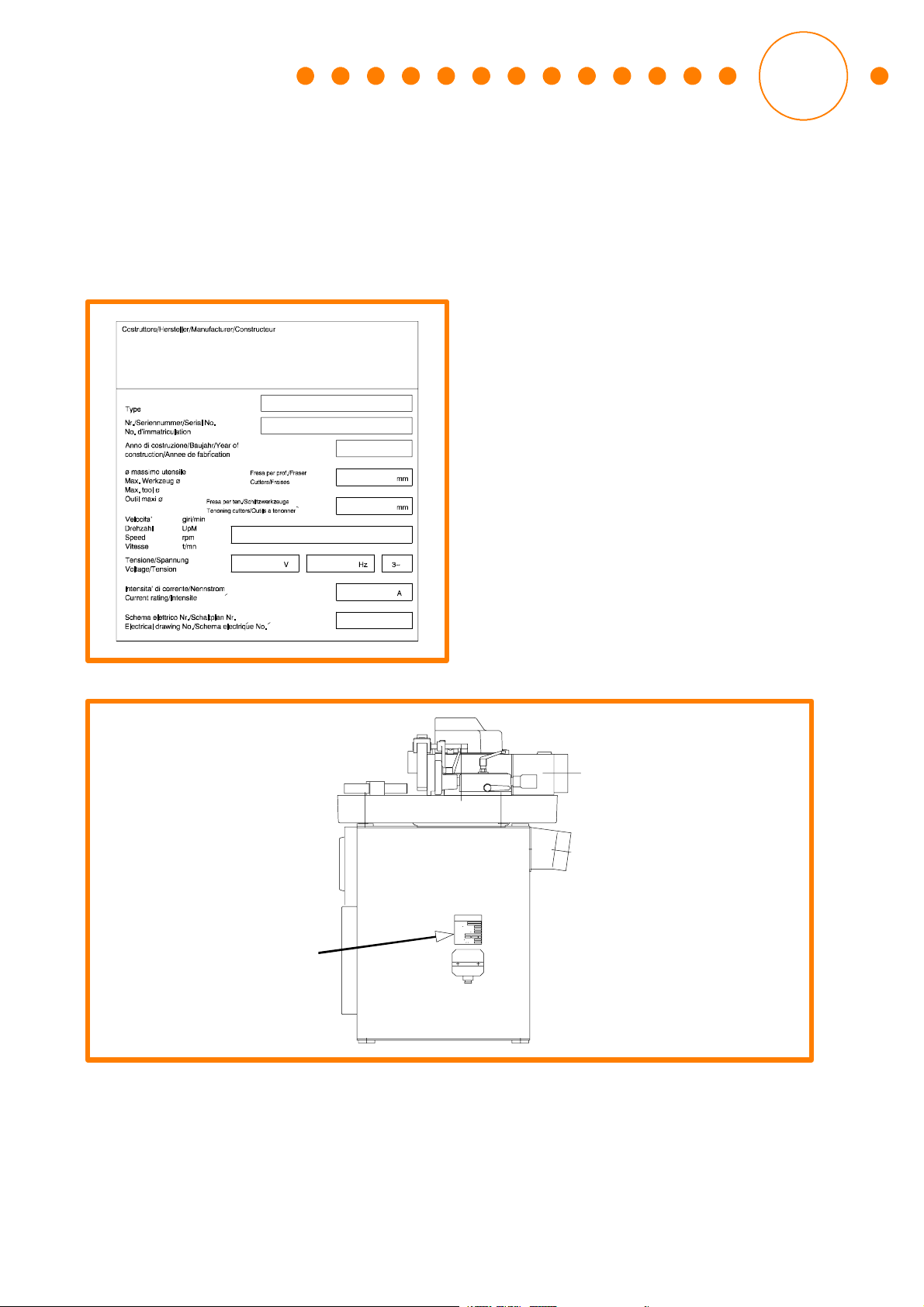
3.4.1 Connection with the electric system 21.......................................
3.4.2 Check of the rotating direction 22...........................................
3.4.3 Connection with the suction system 22.......................................
4 MACHINE START-UP AND USE 25......................................
4.1 CONTROL LIST AND FUNCTIONS 25.........................................
4.2 SPINDLE POSITIONING 26..................................................
4.3 PREVENTIVE CHECKS 26...................................................
4.4 TOOLS 26..................................................................
4.4.1 Features of the tools that can be installed 26.................................
4.4.2 Tool handling 27..........................................................
4.5 INITIAL ADJUSTMENTS AND OUTFIT 28......................................
4.5.1 Installation of the interchangeable spindle 28.................................
4.5.2 Removal of the interchangeable spindle 29...................................
4.5.3 Tool installation on the spindle 30...........................................
4.5.4 Selection of the tool rotating speed 32.......................................
4.6 SAFETY OPERATING PROCEDURES 35......................................
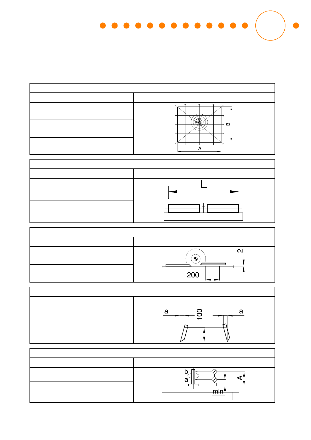
4.6.1 Dimensions of the pieces being machined 35.................................
4.6.2 Machine adjustment and installation 36......................................
4.6.3 Tool adjustment on the machine 36..........................................
4.6.4 Guide adjustment 36......................................................
4.6.5 Rotating directions 36.....................................................
4.6.6 Speed selection 36........................................................
4.6.7 Machine operation, guard choice and adjustments 36..........................
4.6.8 Guide machining with cutting through all the piece length 37....................
4.6.9 Interrupted machining 37...................................................
4.6.10 Shaft machining 38........................................................
4.6.11 Simultaneous machining 38................................................
4.6.12 Other machinings 38......................................................
4.6.13 Noise reduction 38........................................................
4.7 OPERATING CYCLE 39......................................................
4.7.1 Spindle start 39...........................................................
4.7.2 Use of the machining guide 39..............................................
4.7.3 Pressing device use for the guide machining 42...............................
4.7.4 Use of the machining guide with three positions (optional) 43...................
4.8 GUIDE MACHINING PROCEDURES 45........................................
4.8.1 Guide machining with cutting through all the piece length 46....................
4.8.2 Interrupted machining 46...................................................

T120C
III
4.9 SHAFT MACHINING PROCEDURES 46.......................................
4.9.1 Milling with the curved guide 46.............................................
4.9.2 Milling with inlet ring 50....................................................
4.10 Tenoning procedure with sliding table 53........................................
4.10.1 Tenoning sliding table 53...................................................
4.10.2 Adjustment of the protecting device for tenoning operations 55..................
4.10.3 Tenoning of straight pieces 56..............................................
4.10.4 Tenoning of sloped pieces 56...............................................
5 MAINTENANCE 59.....................................................
5.1 MAINTENANCE AND SAFETY 59.............................................
5.1.1 Safety measures 60.......................................................
5.1.2 Tool maintenance 60......................................................
5.2 ELECTRIC SYSTEM MAINTENANCE 60.......................................
5.3 SELF-BRAKING MOTOR 61..................................................
5.3.1 Entrefer adjustment 61....................................................
5.3.2 Replacement of the movable anchor - brake disk (12) 62.......................
5.3.3 Replacing the electro-magnet (11) 63........................................
6 WHAT YOU MUST DO IF... 65...........................................
6.1 FOREWORD 65.............................................................
6.1.1 The spindle overload cutout does not reset 65................................
6.1.2 The spindle motor rotates always braked 65..................................
6.1.3 The spindle motor overload cutout has intervened at the switching-on 66.........
6.1.4 The overload cutout of the spindle motor has intervened 66.....................
6.1.5 Piece surface being machined not smooth 66.................................
7 TECHNICAL AND ENVIRONMENTAL DATA 67...........................
7.1 TECHNICAL DATA 67.......................................................
7.2 OVERALL DIMENSIONS 71..................................................

T120C
IV
TABLES INDEX
Table 1: Safety plates 10.............................................................
Table 2: Machine weight 17...........................................................
Table 3: Lifting load reduction 18......................................................
Table 4: Cable section and fuse size 21................................................
Table 5: Selection of the tool rotating speed 33..........................................
Table 6: Dimensions of the pieces being machined 35....................................
Table 7: Entrefer and friction material 61................................................

T120C
1
1 INTRODUCTION
1.1 MACHINE DESCRIPTION
Vertical single shaft milling machine, for machining wooden pieces by chip removal with
rotary tool installed on the shaft.
The machine has manual feeding, with a single vertical shaft, which can be fixed or in-
terchangeable, with fixed position during the machining and a horizontal supporting
plane, fixed during the machining. The shaft passes through the plane, and the driving
motor is positioned below. The machine can have one or more of the following configur-
ations:
•the possibility of choosing up to 5 rotation speeds for the tools depending on
their diameter and type of machining to be made;
•the possibility of adjusting the shaft in vertical position through the plane;
•the possibility of increasing the supporting surface by adding additional planes;
•motor direct starting by push button;
•the reversal of the shaft rotation direction;
•possibility of installing the interchangeable spindle.
1.2 CONFORMITY
The machine has been planned and built according to the norms ANSI 01.1: April 1991
SAFETY REQUIREMENTS FOR WOODWORKING MACHINERY.
1

T120C
2
1.3 MACHINE IDENTIFICATION
1.3.1 Machine identification
The machine is identified by the writings shown on the plate (Fig. 1) placed on the base-
ment as indicated in Fig. 2.
’’
Fig. 1: Machine identification plate.
’’
3~HzV
Curr ent rating/Intensite
Tensione/Spannung
Voltage/ Tension
gir i/ mi n
UpM
rpm
t/mn
Veloci ta’
Dr ehzahl
Vitesse
#f8 mas sim o utensil e
Max. Werkzeug #f8
Max . tool #f8
Outil maxi #f8 mm
mmCutters/F raises
Nr ./Ser iennumm er/ Seri al N o.
No.d’immatriculation
Fig. 2: Position of the identification plate
1.3.2 Correspondence
When communicating with the Dealer or the Technical Service Center or the Manufac-
turer, for any reason concerning the machine, always refer to the following data:

T120C
3
•Machine model
•Machine serial number
•Manufacturing year
1.3.3 Service recommendations
When preparing this instruction handbook, all the operations involved in the routine
maintenance have been considered.
We recommend you not to make any repair or intervention not indicated in this hand-
book.
All the operations needing to remove some parts must be carried out by qualified and/or
authorized technical staff.
Only skilled and trained staff is authorized, after having read this handbook, to use the
machine and to carry out the maintenance operations.
As for technical problems for the Service, give the following information as well:
•Connection voltage
•Frequency
•Purchase date
•Detailed information on the possible found failure
•Detailed information on the special machining to be made
•Use period / operating hours

T120C
4
1.3.4 Final test report
The factors for the final test of the machine geometry are referred to the norm ISO 7009,
and particularly:
Machining table flatness
Tolerance
Longitudinal (A) 0.15 mm
Diagonal (A) 0.25 mm
Transversal (B) 0.15 mm
Longitudinal rectilinearity of the machining guide shoulders
Tolerance
Wood 0.40 mm
Aluminum 0.15 mm
Parallelism of the machining guide shoulder planes
Tolerance
Wood 0.20 mm
Aluminum 0.05 mm
Perpendicularity of the machining guide shoulders to the machining table
Tolerance
Wood a= 0.20 mm
Aluminum a= 0.10 mm
Radial swinging of the tool-holding shaft
Tolerance
>pos.: a; 6000 min
-1
0.020 mm
>pos.: b; 6000 min
-1
A
max
= 200 mm
0.030 mm

T120C
5
Flatness of the tool supporting surface
Tolerance
0.020 mm
Perpendicularity of the tool-holding shaft to the machining table
Tolerance
0.10 mm
Flatness of the spacer supporting plane
Tolerance
0.20 mm
Seller’s/dealer’s stamp

T120C
6

T120C
7
2 WORKING SAFETY
2.1 GENERAL SAFETY RULES
The machine operator and the person in charge must read this instruction handbook
carefully and completely before executing any operation on the machine.
Keep this handbook close to the machine.
The manufacturer is continuously improving the products, so some machine compo-
nents may possibly change.
All the technical information in this handbook are exclusive property of the manufac-
turer and are strictly confidential.
Thus, it is forbidden to reproduce and disclose them, even partially, without a written
authorization by the manufacturer.
It is also forbidden to use this handbook for purposes other than those strictly con-
nected with the installation, use and maintenance.
For detailing shortly and clearly the operation, adjustments and other, some figures
may show the machine without safety guards. DO NOT USE the system under these
conditions, and in case of maintenance or repair interventions follow the indications in
the chapter: MAINTENANCE.
2.1.1 Operator training
It is extremely important that all the operators are suitably trained in the use, adjustment
and utilization of the machine.
Above all:
a) the principles for adjusting and using the machine, including a correct use and ad-
justment of the devices for guiding and holding the piece, guards and tools.
b) The tool correct selection for each operation.
c) The position of the hands with respect to the tool.
2

T120C
8
d) The safe piece handling while machining, following the recommendations for
using templates and similar devices:
•to use roller devices or extension tables when long pieces are machined.
e) The safe storage of pieces before and after the machining.
f) The correct adjustment of the safety devices.
g) To start the machining only when the tools have reached the operating speed.
h) The use of personal protections for the ears, eyes and lower limbs.
This machine has been designed and manufactured to give the user a suitable safety
but, like all machines provided with cutting systems, it may cause dangerous situations
due to incorrect use of the machine, lack of experience or tampering with the safety
devices of the machine; therefore the operators should take these remarks into ac-
count and carefully follow the instructions given in this handbook about safety.
2.1.2 Safety plates
On the machine (Fig. 3) some safety plates, Table 1 have been installed to warn the
operator about the residual risks on the machine, the suitable use of the working equip-
ment and the safety measures that must be followed during the maintenance interven-
tions.
WOR K AREA.
FIR E RISKS.
FACTORY.
CAN C AUSE SEVER INJU RES.
ETC.CONFINE HAIR.
OR LOOSEN TOOLING.
LEFT IN OR ON THEMACHINE.
SAFETY R ULES
IMPORTANT SAFETY PROCEDURES
READ AND UNDERSTAND CLEARLY
THE ALTERN ESS
DANGER
HIGHT VOLTAGE
spasueri alfredo
Type
mm
3~
mm
’’
HzV
gir i/ mi n
UpM
t/mn
rpmSpeed
Max. tool#f8
Outilmaxi#f8
Veloci ta’
Dr ehzahl
Vitesse
100008000600045003000
min
--1
T120
sueri
100009000750070006500600055005000450040003500300028002500 ..
_
_
_
_
_
_
_
_
84
63
52
42
31
75
66
57
47
38
85
84
75
67
59
50
42
33
79
71
63
55
47
39
85
37
44
34
413835
82
7973
7065
596368
7581
73
66615753
47505459
51484441
42
47
52
59
66
71
75
82
84
79
73
65
58
52
47
42
37
38
37
37
35
8070
6473
6759
5563
5951
4652
46
42
40
60
55
50
47
44
39
56
51
47
44
41
37
50
46
42
39
37
380
350
320
300
280
250
220
200
180
160
140
120
100
80
60
CAUTION
SPIND LE
DANGER
DO NOT MAKE
3,000
4,500
6,000
8,000
10,000
65294550
DANGER
DO NOT REMOVE
Fig. 3: Position of the safety plates
Safety plates in English have been positioned on the machine. Plates in Spanish are
supplied as well, to be positioned on the machine in case of need for the operator.

T120C
9

T120C
10
Table1: Safety plates
2.1.3 Symbols
To point out the handbook sections concerning personal safety, the following symbols
have been used in the USE AND MAINTENANCE operations of the machine:
ATTENTION
Information or procedure that, if not carefully followed, could cause death or serious
personal injuries.
CAUTION
Information or procedure that, if not carefully followed, could cause light personal in-
juries or machine damages.
ELECTRIC DANGER
Information or procedure that, if not carefully followed, could cause death or serious
personal injuries.
WARNING
Information or procedure that aids the operator in the best use of the machine
or equipment, to lengthen their life, avoid damages or programming losses, op-
timize the work in compliance with safety norms.

T120C
11
NOTE
Important information or procedure
It is recommended to use the personal protection devices for the eyes.
It is recommended to use the personal protection devices for the ears.
It is recommended to use the personal protection devices for the hands.
It is recommended to use the personal protection devices for the lower limbs against
the squeezing due to falling pieces during the operation.
2.2 MACHINE CORRECT AND IMPROPER USE
The machine can carry out milling operations (profiling and tenoning) on deadwood,
veneered wood, plastic materials with features similar to wood.
Any other use or machining on a material other than the indicated ones (for example
metals or materials with similar features) is forbidden, as it can be risky for the operator.
The manufacturer will not be responsible for damages or injuries to people and/or
things caused by a use non-complying with the norms. The risk will exclusively be at
the user’s charge.
This machine cannot operate in explosive environments.
2.2.1 Number and position of the working places
For a correct and safe use of the machine a single operator is expected, whose working
place is located in front of the guard for the guide machining.

T120C
12
Fig. 4: Working place
2.3 INDIVIDUAL RISK FACTORS
Some clothes or accessories worn by the operator can cause accidents. It is advisable
to avoid wearing dangerous objects, such as: rings, watches, bracelets, large-sleeved
overalls, not perfectly fastened belts, ties and, generally, anything sticking out of the
person that may be grasped by a moving part of the machine during its operation:
people with long hair should keep it gathered on the back of the neck, and possibly wear
a cap.
People not belonging to the work place shall absolutely stay far off the operating ma-
chine.
2.4 ENVIRONMENTAL RISK FACTORS
The place of work must be properly illuminated.
The operations performed by the machine produce dust and, in general, the machine
is in a place where other machines spread dust in the environment; to avoid dangerous
dust concentrations it is necessary:
•to make a correct connection with the suction system;
•to periodically carry out the maintenance on the suction system filters;
•further, as the dust deposited on the floor generates danger conditions, it is
necessary to carefully clean the place of work close to the machine periodically.
2.5 RISK FACTORS CONNECTED WITH THE MACHINE USE
•When the machine is connected to the mains, check the correspondence be-
tween the electrical features of the machine and those of the mains; it is also

T120C
13
advisable to check the correct grounding of the machine; these steps must be
recalled to the specialized technician carrying out the electrical connection.
•Before carrying out any maintenance on the machine, switch and cut it off from
power sources, set the main switch on zero and lock it.
•Machining pieces that are too small or too big for the machine capacity may
cause a dangerous situation for the operator or the people near the machine;
always compare the sizes of the pieces being machined with the max. and min.
dimensions that the machine can work.
•Do not remove or change the protection devices to change the operating ca-
pacity of the machine.
•Be very careful when choosing and maintaining the tools.
•Never use cracked, strained or excessively worn tools, as their utilization im-
pairs the machining quality and can involve risks for the people nearby the ma-
chine, as well as further increase the machine noise.
•Always wear gloves when handling the tools; refer to the data in the handbook
for the knife locking and projecting, as well as for the best adjustment of the
knife locking screws.
•A correct maintenance will ensure higher working safety as well as a constant
quality level of the machining.
•The protection devices must be regularly checked for their operation, for
example before every working shift.
2.6 PROTECTION AND SAFETY DEVICES
The machine is equipped with the following protection and safety devices:

T120C
14
8000600045003000
min
--1 10000
Fig. 5: Protection and safety devices
a) emergency push button
b) lockable main switch
c) self-braking motor with intervention lower than 10 s;
d) interlocked front cover; it stops the spindle rotation when opened
e) guard interlock micro-switch
f) machining guide
g) guard - chip conveyor for the guide machining
h) machining guide upper cover
i) front guard for the guide machining
j) upper cover locking pin
k) adjustable shoulders for the machining guide.
It is important to check the correct operation of the safety and protection devices as
indicated in § 5.1.1.
Table of contents
Popular Power Tools manuals by other brands

Silverline
Silverline 633567 quick start guide

VONROC
VONROC JS503AC Original instructions

Bosch
Bosch GSB 36 V-LI Professional Original operating instructions

TOOL WAREHOUSE
TOOL WAREHOUSE KSD507 quick start guide

Rema Tip Top
Rema Tip Top T2-Compound Master operating instructions

MEM
MEM TQ-4050 operating instructions