Technical Documentation
Page 10
Sacher Lasertechnik GmbH Tel.: +49 6421 305-0 Sacher Lasertechnik, LLC Tel.: 1-714-670-7605
Rudolf Breitscheid Str. 1-5 Fax: +49 6421 305-299 5765 Equador Way Fax: 1-714-670-7662
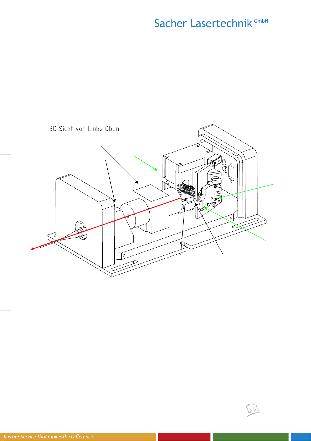
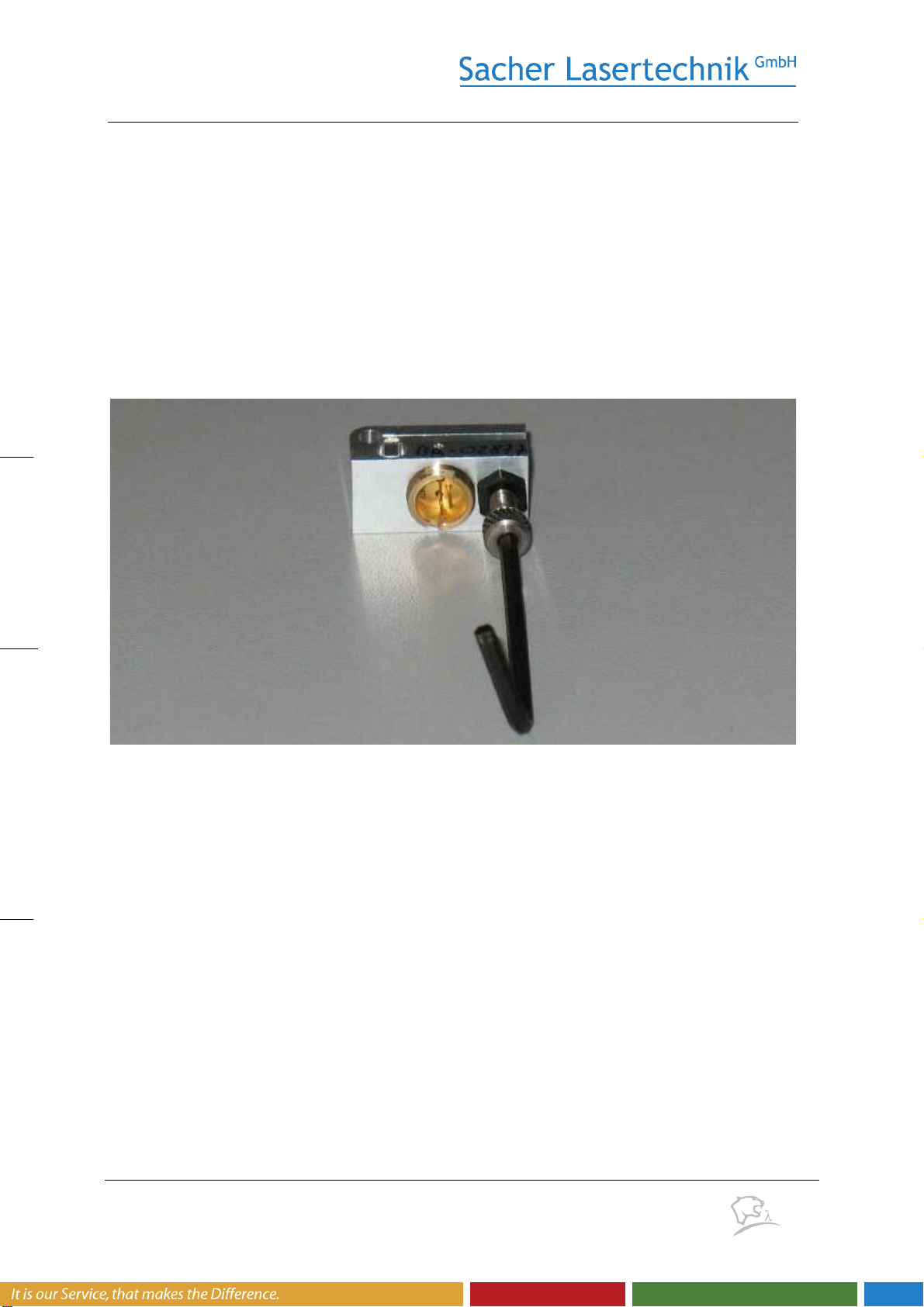
L) The optimization of the cavity will be performed via the cavity alignment screw. Once
laser action is found, no more than +/- 1 rotation of the cavity alignment screw is
required.
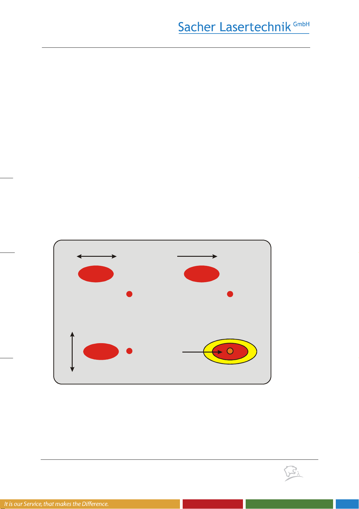
M) A typical dependence of the laser power on the cavity alignment is shown in Fig. 8.
Usually, the best adjustment is achieved as soon as the laser power reaches its
maximum value. Make sure that the laser is not operating at a side maximum by
verifying the cavity alignment according to Fig. 8. Otherwise you will not be able to
achieve the specified values.
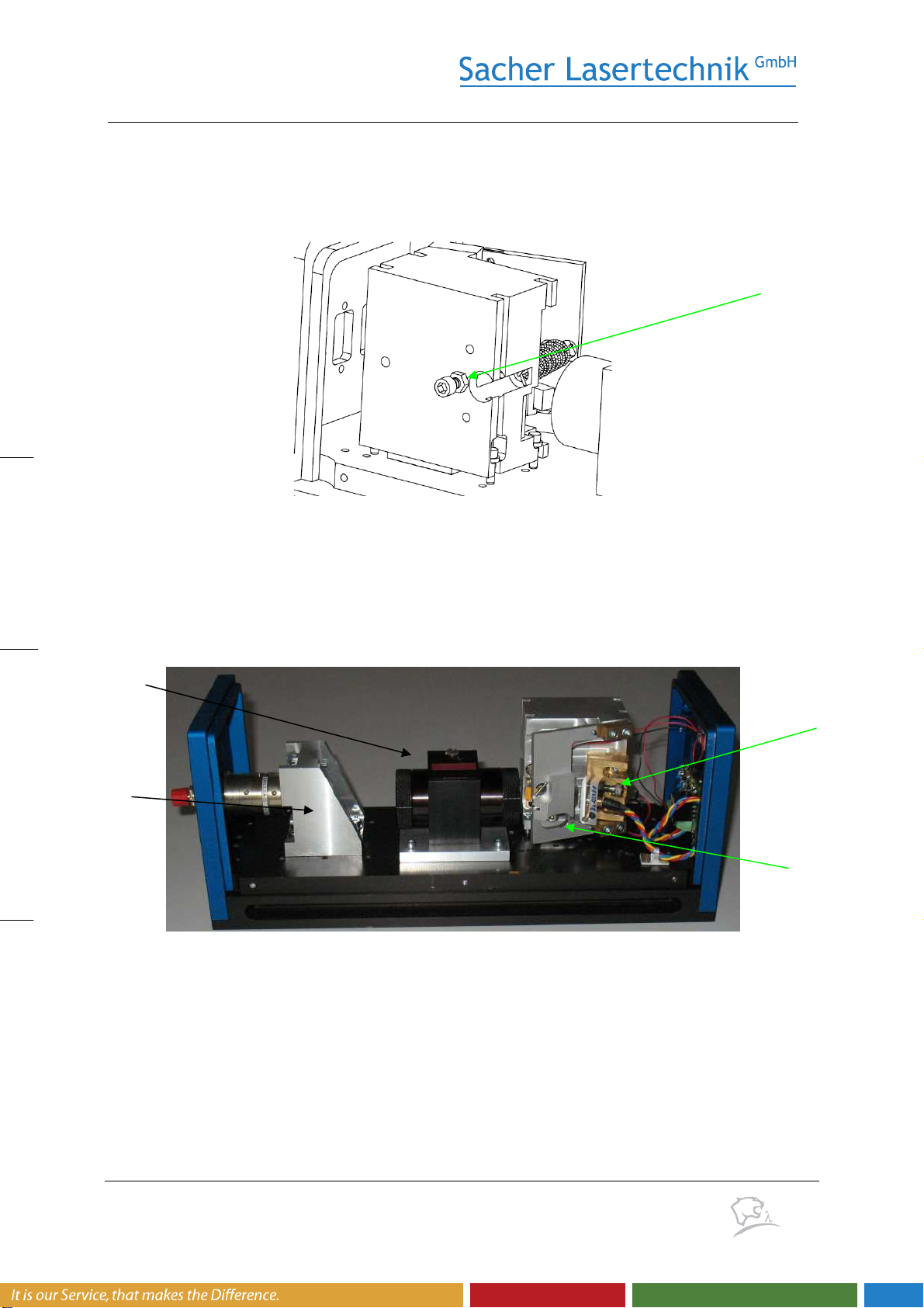
N) After optimization of the cavity alignment screw, you may try to optimize the laser
collimation for improving the laser power. No more than 1/8 of a turn of the collimator
adjustment screw will be required.
O) Repeat step L) and M) until the maximum power is achieved.
Please note that it may be difficult to determine which cavity alignment maximum will
provide the provides the highest power and the best laser performance.
Furthermore, there are types of laser diodes where the alignment for the highest power
does not coincide with the alignment for the best laser performance.
Therefore after optimizing the laser for the highest power, it is recommended to check the
minimization of the threshold current due to the feedback of the external cavity.
3.2 Minimizing the Laser Threshold
When optimizing the cavity adjustment via the cavity alignment screw, you may find
several maximum within the laser power as a function of the cavity alignment screw as
indicated in Fig. 8. Only one of these power maximum will provide you the best laser
performance.
Please note that the maximum with the highest power does not necessarily provide the
best over all performance of the laser system. A procedure for choosing the best
alignment is to check which power maximum offers the lowest threshold current.
A simple method for monitoring the threshold current as follows. Required items are an
oscilloscope, a power meter with a monitor exit and a signal generator.
A) Connect the laser current modulation input of the laser controller to signal generator
which provides a triangular voltage signal.
B) Alternatively, you may use the internal Ramp Generator function of the laser controller
together with the Current Coupling function of our laser controller for generating the
laser current modulation.