Ninglu AM706-H User manual

Website:www.ninglutech.com
Document:NLT-AM706-SSEN
Edition:V190314
Anemometer AM706-H
Operation & Installation Manual

*** Quick Operating Guide ***
[Mode]:Relative speed/direction + True
speed/direction mode and Relative
speed/direction + Max speed + Average
speed mode
[MENU]:Set Wind Alarm, Speed Unit,
Avg Time, Input Show, Language, Back
Color and Dig Color.
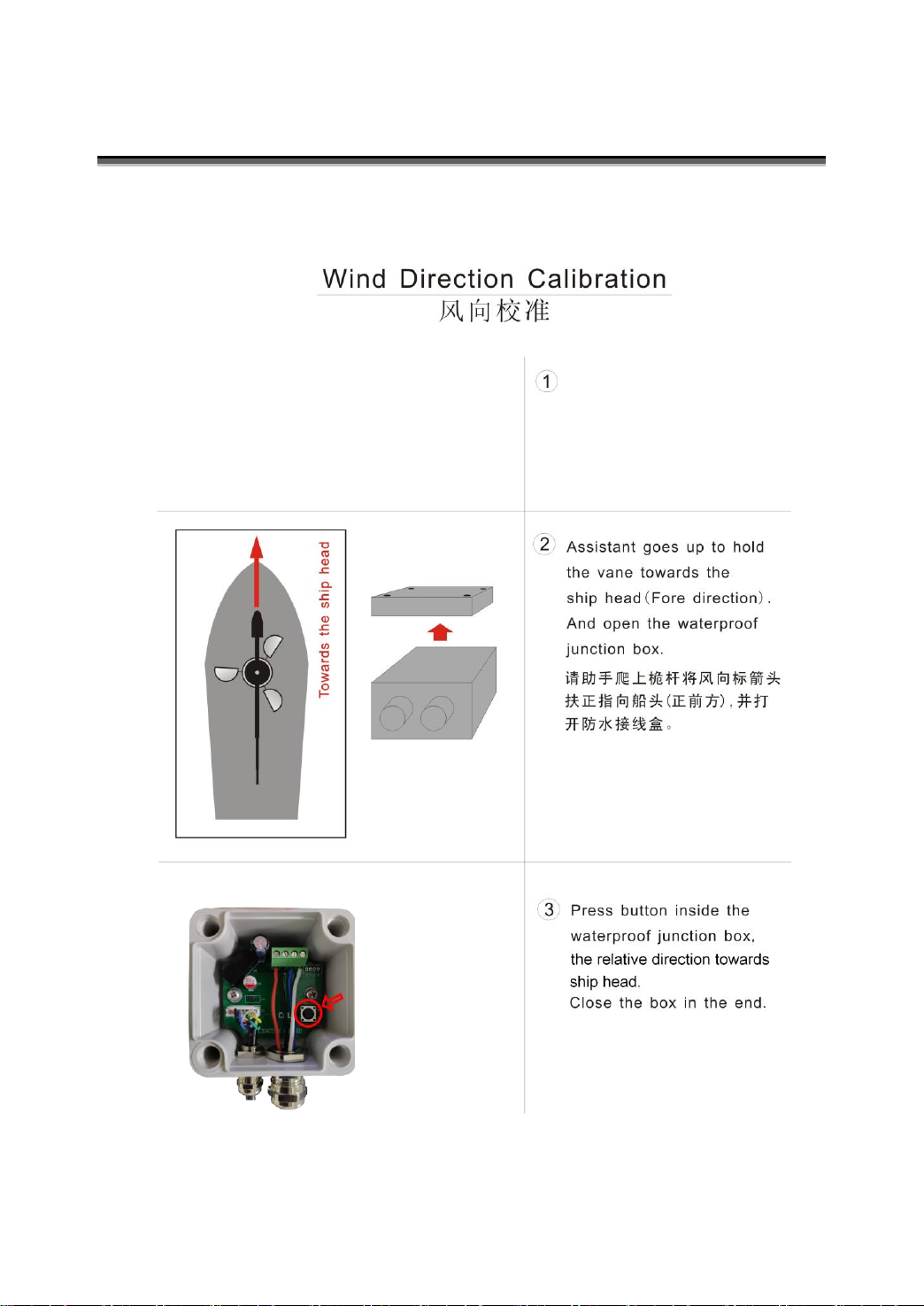
Calibration:After finishing the main unit
AM706E installation and power on, hold
the wind vane to the direction of the bow
line, then push the button in the junction
box.

Contents
Introduction....................................................................1
System Composition...............................................................................1
Main Unit AM706E........................................................................1
Sensor unit AM706H.....................................................................1
Principle of Measurement.......................................................................2
Function and Operation................................................3
Display Layout........................................................................................3
Function..................................................................................................3
Power on/off ....................................................................................3
Brightness........................................................................................3
OK...................................................................................................4
Day/Night Mode...............................................................................4
MODE..............................................................................................4
Arrow Keys......................................................................................5
MENU..............................................................................................5
Wind Alarm ..................................................................................5
Speed Unit...................................................................................6
Avg Time......................................................................................6
Input Show...................................................................................6
Language.....................................................................................7
Back Color ...................................................................................7
Dig Color......................................................................................7
Default .........................................................................................7
Send Ture....................................................................................7
Data transmission for NMEA0183...........................................................8
Main Unit Output --MWV .................................................................8
GPS Data Input--RMC.....................................................................8
GPS Data Input--VTG......................................................................9
Speedlog Data Input--VBW .............................................................9
Speedlog Data Input--VHW...........................................................10
Gyro Data Input--HDT ...................................................................10
Specification ................................................................11
Basic Specification................................................................................11
Environmental Conditions.....................................................................11

Technical Specification..........................................................................12
Maintenance.................................................................13
Main Unit ..............................................................................................13
Sensor Part...........................................................................................13
Calibration....................................................................14
Installation....................................................................15
Installation of Main Unit AM706E..........................................................15
Power Adapter Installation....................................................................16
Installation of Wind sensor AM706H.....................................................17
Wiring Explanation......................................................18
System View.........................................................................................18
Wiring Diagram of AM706E Back Cover...............................................19
System External Wiring Diagram..........................................................20
Appendix ......................................................................21

1
Introduction
The Marine Anemometer AM706-H is a combined instrument for wind speed
and direction. It can measure relative wind speed (accuracy ±5%, min
0.1m/s), relative wind direction (digital display accuracy 1 °, analog display
accuracy 10 °and output accuracy ±1 °). GYRO(HDT), SPEEDLOG(VBW)
or GPS (RMC/VTG) data user can select relative wind mode and true wind
mode.
Main unit AM706E can be installed by the table, hanging and flush mounting
methods. Sensor AM706H should be installed in the place with free
wind in the ship.
System Composition
Main Unit AM706E
Direction Display:Analog and digital display of relative (to the bow) and true
wind direction
Speed Display:Digital display of relative, true, max and average wind speed.
Sensor unit AM706H
Wind speed sensor:Wind speed sensor has a rotor with three wind cups.
Wind direction sensor:Wind direction sensor has a wind vane to drive an
absolute angle sensor unit.
Holder:Used to install wind speed sensor and direction sensor for fixation of
junction box
Junction box:Consist of waterproof junction box and sensor unit transmitter.

2
Introduction
Principle of Measurement
The wind speed sensor has a rotor with three wind cups which spins as the
wind moves past the boat. The Wind speed sensor measures how fast the
rotor is spinning to calculate the wind speed. The wind direction sensor has a
wind vane which points in the direction that the wind is coming from. The wind
direction sensor electronically senses the direction the wind vane is pointing.
With inputting GYRO(HDT), SPEEDLOG(VBW)or GPS (RMC/VTG) data,
calculate and display the true wind speed and direction(relative to north
pole).
3
Function and Operation
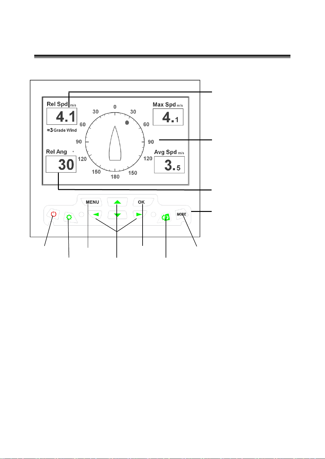
Display Layout
Function
Power on/off
Press the on-off key to turn on /off the system.
Brightness
In Day/Night mode, press the brightness key to adjust the screen brightness.
There are 9 levels for selection.
Power on/off Menu OK Mode
Brightness Arrow keys Day/Night Mode
Wind Direction Digital Display
Wind Speed Digital Display
Operation Keyboard
Wind Direction Analog Display

4
Function and Operation
OK
Press [OK] key to save the settings in the menu and return to the main
screen.
Day/Night Mode
Press the Day/Night mode key to switch the day mode and night mode.
MODE
Press [MODE] key to select Relative Mode(relative speed + relative angle +
max speed + average speed)and True Mode(relative speed + relative angle
+ true speed + true Angle).
Relative Mode True Mode
Note:The wind grade (see Appendix)can only be shown in relative mode.
The ship speed and heading can be only shown in true mode.

5
Function and Operation
Arrow Keys
In the menu mode, press up/down arrow keys to select the setting items and
press left/right arrow keys to select the setting values.
MENU
Menu Explanation
Item
Range
Default
Wind Alarm
[Off 1~60m/s]
Off
Speed Unit
[m/s km/h knots]
m/s
Avg Time
[1 min 2 min 5 min 10 min]
10 min
Input Show
[Off On]
Off
Language
[English 中文]
English
Back Color
[Light-Blue Blue Black]
Light-Blue
Dig Color
[Yellow in Blue Green in Black White in
Black]
Yellow in Blue
Default
[Off Reset]
Off
Send Ture
[Yes No]
No
Wind Alarm
Set the relative wind speed alarm values. When the relative wind speed is
larger than the relative wind alarm value, the system will give the alarm signal
after 30s with beep and speed numbers become red color and flash. Press
any key to mute the beep but the relative speed numbers are still in red color
and flash. When the relative wind speed is less than the relative wind alarm

6
Function and Operation
value, the relative speed numbers return to white color and not flash. Then
the system will be working normally.
Press up/down arrow keys to select the item ‘Wind Alarm’and press left/right
arrow keys to set the wind alarm values.
Setting Range is 1~60m/s and default is Off
Speed Unit
Set the wind speed unit. Press up/down arrow keys to select the item ‘Speed
Unit’and press left/right arrow keys to select speed unit.
1~60m/s and default is Off
Setting Range is m/s, km/h and knots and default is m/s.
Avg Time
Set the computing period of the max speed and average speed. Press
up/down arrow keys to select the item ‘Avg Time’and press left/right arrow
keys to set the period.
Setting Range is 1 min, 2 min, 5 min and 10 min and default is 10 min.
Input Show
Set the input display of Gyro, Speedlog and GPS. Press up/down arrow keys
to select the item ‘Input Show’and press left/right arrow keys to select on and
off.
Setting Range is Off and On and default is Off.

7
Function and Operation
Language
Set the system language. Press up/down arrow keys to select the item
‘Language’and press left/right arrow keys to select English and Chinese.
Setting Range is English and 中文 and default is English.
Back Color
Set the background color. Press up/down arrow keys to select the item ‘Back
Color’and press left/right arrow keys to select the colors.
Setting Range is Light-Blue, Blue and Black and default is Light-Blue.
Dig Color
Set the window and number colors. Press up/down arrow keys to select the
item ‘Dig Color’and press left/right arrow keys to select the colors.
Setting Range is Yellow in Blue, Green in Black and White in Black and
default is Yellow in Blue.
Default
Reset the system. Setting Range is Off and Reset, and default is Off.
Send Ture
Set the transmitted relative or true sentence. Yes is to transmit relatvie and
true sentence and No is to transmit relative sentence.

8
Function and Operation
Data transmission for NMEA0183
Main Unit Output --MWV
$--MWV, x.x , a , x.x , a , A*hh<CR><LF>
1 23456
1) Wind angle, 0 to 359 degrees
2) Reference, R = Relative, T = Ture
3) Wind Speed
4) Wind Speed Units, K=km/h / M=m/s / N=knots
5) Status, A = Data Valid, V = Data invalid
6) Checksum
GPS Data Input--RMC
$--RMC, hhmmss.ss,A,llll.ll,a,yyyyy.yy,a,x.x,x.x,xxxxxx,x.x,a,a*hh<CR><LF>
12 345 67 8 9 10
1) UTC Time
2) Status, A=Data valid, V = Navigation receiver warning
3) Latitude,N or S
4) Longitude,E or W
5) Speed over ground, knots
6) Course Over Ground, degrees true
7) Date:ddmmyy
8) Magnetic Variation, degrees,E or W
9) Mode Indicator
10) Checksum

9
Function and Operation
GPS Data Input--VTG
$--VTG, x.x,T , x.x,M , x.x,N , x.x,K , a*hh<CR><LF>
1 2 3456
(1) Course over ground, degree true
(2) Course over ground, degree magnetic
(3) Speed over ground, knots
(4) Speed over ground, km/h
(5) Mode indicator,A=Autonomous mode
D=Differential mode
E=Estimated(dead reckoning)mode
M=Manual input mode
S=Simulator mode
N=Data not valid
(6) Checksum value
Speedlog Data Input--VBW
$--VBW, x.x , x.x , A , x.x , x.x , A , x.x , A , x.x , A*hh<CR><LF>
12 3 4 5 678910 11
(1) Longitudinal water speed, Knots
(2) Transverse water speed, Knots
(3) Status:water speed, A=data valid, V=data invalid
(4) Longitudinal ground speed, Knots
(5) Transverse ground speed, Knots
(6) Status:ground speed, A=data valid, V=data invalid
(7) Stern transverse water speed, Knots
(8) Status:stern water speed, A=data valid, V=data invalid
(9) Stern transverse ground speed, Knots
(10) Status:stern ground speed, A=data valid, V=data invalid
(11) Checksum value

10
Function and Operation
Speedlog Data Input--VHW
$--VHW, x.x,T , x.x,M , x.x,N , x.x,K*hh<CR><LF>
12 3 4
(1) Heading, degrees True
(2) Heading, degrees Magnetic
(3) Speed, knots
(4) Speed, km/hr
Gyro Data Input--HDT
$--HDT, x.x , T * hh<CR><LF>
123
(1) Heading, degree true
(2) T = true
(3) Checksum value

11
Specification
Basic Specification
Main Unit Dimension(AM706E):W188mm H166mm D65 mm
Weight:Main Unit 2kg Sensor 8kg
Power Supply:24V DC (20-32V)
Power through adapter:110/220V 50/60Hz AC
Power:< 5W (24V DC)
NMEA Input Baud Rate:4800bps (9600 bps for GPS data input)
Wind Output Baud Rate:4800bps
Data Input:RS422 and NMEA0183 Standard
Sensor Dimension(AM706H): H590mm Activity Radius 320 mm
Environmental Conditions
Working Temperature:Main Unit -20°C ~+55°C
Sensor -20°C ~+85°C
Storage Temperature:Main Unit -20°C~+70°C
Sensor -20°C~+85°C
Humidity:Main Unit 10%~90% RH
Sensor 10%~100%RH
Protection:IP 23

12
Specification
Technical Specification
Wind Speed Range:0~60m/s
Wind Speed Accuracy:±5%(min0.1m/s)
Wind Direction Range:0~359°
Wind Direction Accuracy:±1°
Min Start Speed:≤0.5m/s

13
Maintenance
Main Unit
The main unit is maintenance-free.
If doing the cleaning, use soft cloth and mild detergent, and avoid water drop.
Sensor Part
When there is ice or dirt on sensor to disturb the normal work, please clear in
time.
Regularly check external mounting bolts to avoid looseness and the abrasion
and ageing of cables
When the equipment breaks down, please contact our engineers of after-sale
service department in time. Please do not do the service by yourself.
14
Calibration
Calibration of AM706 wind vane after finishing the installation.
风向标指向船头的同时,按下防水接
线盒的按钮。
最后关上防水接线盒。
Press POWER key to turn power on.
按主机上的开关键开机

15
Installation
Installation of Main Unit AM706E
The Main unit AM706E has three mounting methods, table, hanging and flush
mounting.
The holder supplied by original factory setting is used in table and hung
mounting.
For flushing mounting, embed the main unit into the bridge control panel (the
dimension is shown below) and tighten the rotary knob to fix the main unit.

16
Installation
Power Adapter Installation
Power adapter(GA-240150),AC220/110V to DC24V,adapter holder and
screws.
Unit:mm
Table of contents
Other Ninglu Measuring Instrument manuals


Popular Measuring Instrument manuals by other brands
 Service manual")


Fluke
Fluke iFlex i2500-18 Quick reference card

Omron
Omron K6CM series Startup guide

Jain Technology
Jain Technology XONIC 100L user manual

Water Specialties
Water Specialties TR15 Operation and maintenance manual

Precision Digital Corporation
Precision Digital Corporation ProtEX-MAX PD8-6000 instruction manual

Rife
Rife mini Instructions and operating manual


