SAFARI R1100 User manual

operating instructions
tripod system
#R1100

Pan Lock
Pan Handle Concentric Lock
Pan Handle Clamp
Slide Lock Lever
Camera Platform
Tilt Drag
Clamp Nut
Bubble Level
Tilt Lock
Quick Release Clamp
¼” and pin carriage
Camera Plate
1.
2.
3.
4.
5.
6.
7.
8.
9.
10.
11.
12.

FEATURES AND CONTROLS
55mm Bowl
Leg Angle Lock
Leg Cover
Leg Lock Lever
Rubber Foot
1.
2.
3.
4.
5.

OPERATING INSTRUCTIONS
Thank you for purchasing the SAFARI
tripod system for use with lightweight
portable video camcorders. They are
intended for use by operators using
MiniDV camcorders in most environments.
HANDLE MOUNTING
The head is supplied with a single pan
handle and clamp, tted to the right side
of the head. Adjust the pan handle to
comfortable length by loosening the pan
handle concentric lock (Fig.1).
Adjust the angle of the pan handle by
loosening the handle clamp lever (Fig.2)
on the side of the handle clamp, rotate
pan handle to required angle and retight-
en the handle clamp lever.
Fig. 1
Fig. 2
Operating Instructions
Before operating please read the follow-
ing operating instructions. Do not omit
any step. N.B. The safe operation of this
equipment is the responsibility of the
operator.

MOUNTING YOUR CAMERA
The best camera control can be achieved
by mounting and balancing the camera’s
centre of gravity over the centre axis of
the head. The head is also equipped with
a sliding camera platform to help you
achieve this.
1) Engage pan lock by rotating the lever
clockwise until rm; engage tilt lock by
rotating the knob clockwise until rm.
2) Remove camera plate by unlocking
the slide lock, rotating the quick release
knob and sliding the camera plate
backwards.
3) Attach the camera to the camera plate
by using the ¼” screw and pin in the
plate.
4) Check that the slide lock is released,
then align the camera plate with the
camera base. Slide the camera with
camera plate forward until the safety
mechanism is engaged.
5) Lock the slide lock when camera is
balanced over the centre of gravity of the
head.
DRAG CONTROL
The SAFARI tripod head provides
adjustment for tilt drag control (Fig.3).
Rotate clockwise to increase friction
resistance, and anti-clockwise to decrease
friction resistance.
Fig. 3

TRIPOD SETUP
Remove the tripod system from the carry
bag and stand on a level surface.
Setup
1. Separate legs slightly so they are parallel.
2. Working with each leg individually, release
the leg lock levers (g.4).
3. Extend to desired length and return leg
Lock levers to locked position. Repeat
Process for remaining legs extending them
to the same length.
4. Spread tripod legs.
5. Level the uid head using bubble level and
ball levelling feature of the uid head.
Minimum height setting
Note: it is recommended that minimum
height position is used only with legs at
their shortest length.
1. Working with each leg, push
The button on the leg angle lock (g.5)
To release and spread the leg to its lowest
Position. The leg angle lock will automati-
cally engage the leg to hold the tripod at its
lowest height position.
2. Repeat for other legs.
Fig. 4
Fig. 5 Position 1 Position 2 Position 3
leg angle lock

TRIPOD PULL DOWN
Mid position setting
The mid-angle position is self engaging
after closing the leg from the fully spread
position. The mid angle position will
increase the footprint of the tripod system
but offers optimum stability.
Remove the camera from the tripod
system. Close the tripod legs so all are
pointing straight down and disengage all
leg lock levers. Holding the bowl, lower
the tripod to its shortest length and
re-engage the leg lock levers.
Close legs together fully and return tripod
to carry bag if nished shooting.
cleaning
WARNING: Do not immerse the
tripod system in any liquid.
WARNING: Do not use stiff brushes,
abrasives or solvents.
To ensure optimum performance
throughout the life of the tripod system
it is recommends regular cleaning of the
tripod system. When the system has
been used in harsh environments, wipe
over with a soft damp cloth as soon
as possible. Use a soft brush to clean
crevices. Remove and clean the camera
plate.

SPECIFICATIONS
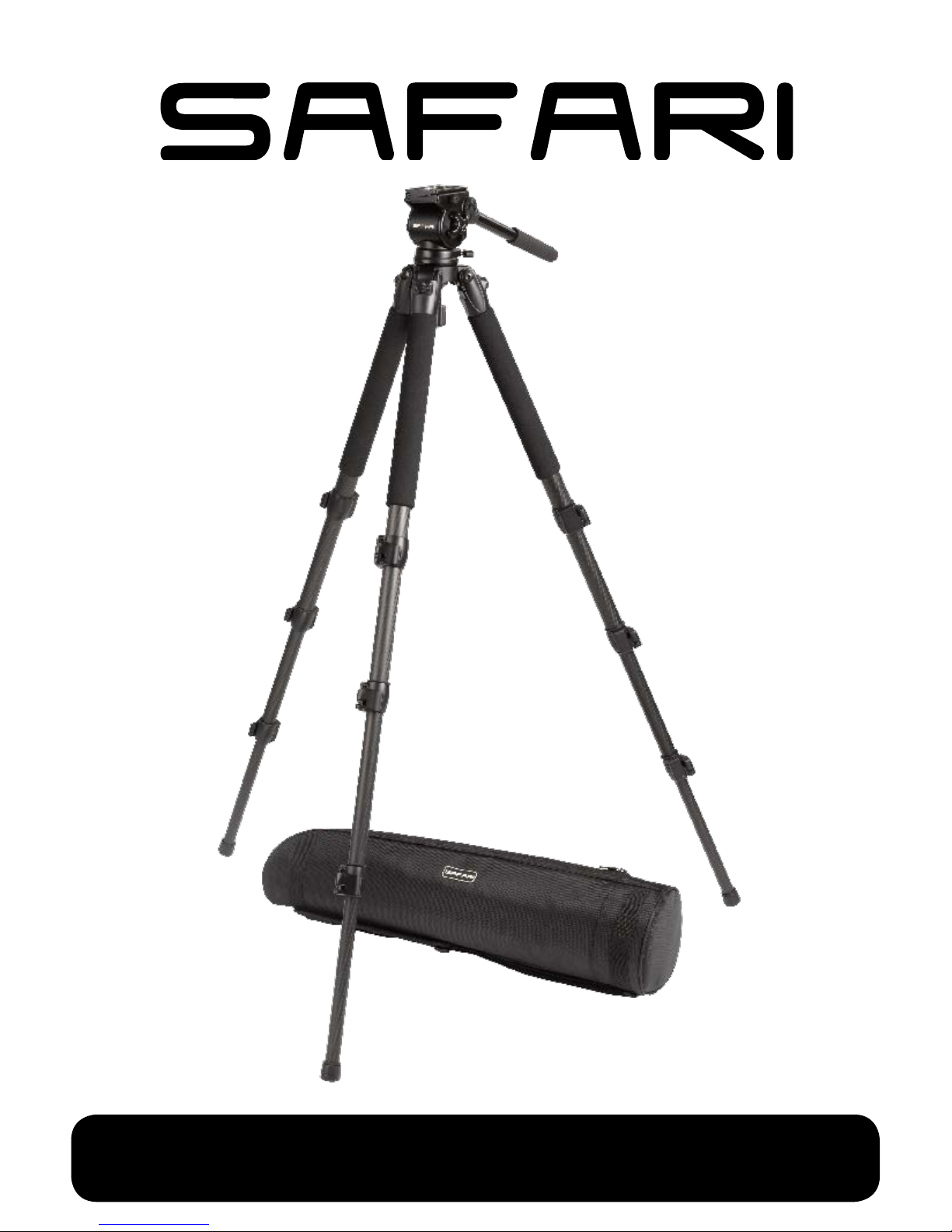
Description SAFARI Tripod System
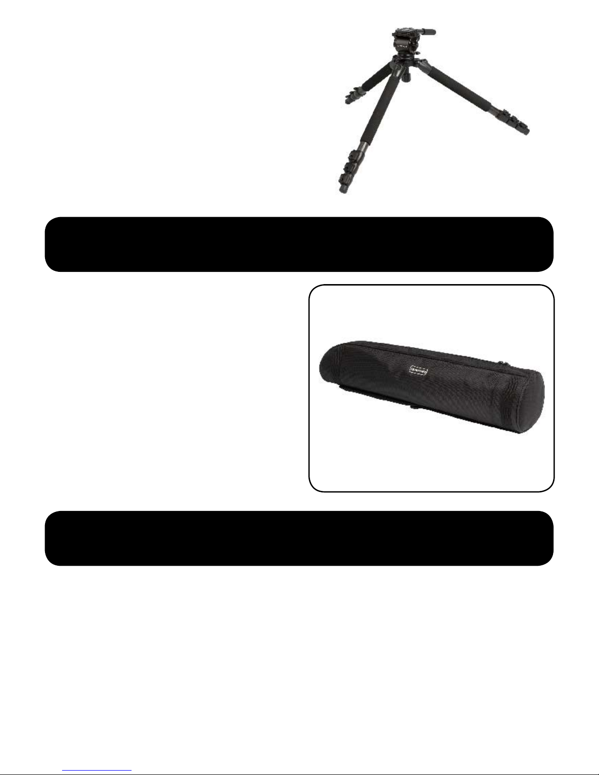
Weight kg (lb) 3.6 kg (7.9)(including soft case)
Payload kg (lb) 5 kg (11.0)
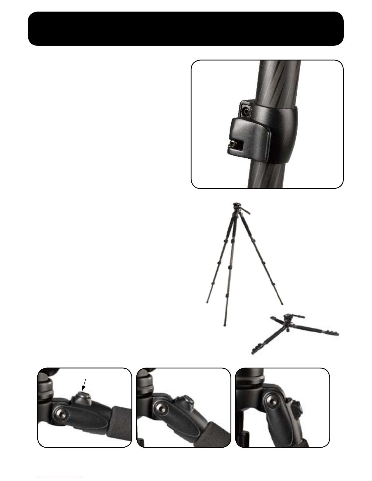
Bowl Diameter 55 mm ball levelling
Height Above Bowl mm (in) 114 mm (4.5)
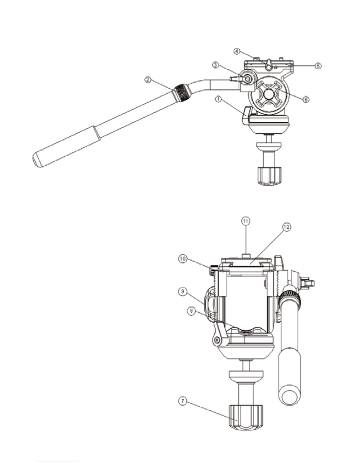
Pan/Tilt System Fluid dampening system
Camera Plate Sliding camera plate
Attachment System ¼” screw with pin carriage
Leg Tube Material Carbon Fibre
Max Height mm (in) 1439 mm (56.7)
Min Height mm (in) 234 mm (9.2)
Transport Length mm (in) 680 mm (26.8)
WARRANTY
This warrants that the safari tripod system supplied
will, under proper use, be free from defects due
solely to faulty material and workmanship for a
period of 1 year from the date of delivery. If part of
the equipment is found by us to be so defective, at
our option, we shall repair or supply a replacement
for such part.
The warranty on this document shall not apply if :
(I) the buyer has, without our consent in writing,
serviced, modied, repaired or otherwise subjected
the goods to technical attention by any person other
than our authorised representatives.
(II) defectiveness is due to neglect, misuse,
excessive heating, accidents, operation contrary to
instructions for use, or normal wear or tear or;
(III) where access to equipment is necessary,
the buyer has not permitted our authorised
representative full access.
It is the buyer’s responsibility when ordering to
ensure that the goods ordered conform to buyer’s
requirements.
www.safaritripod.com
Contact Details:
REM
PO BOX 696 ARTARMON NSW 1570
EMAIL: info@safaritripod.com
For further information on available parts
and accessories visit
Table of contents
Popular Camera Accessories manuals by other brands

Watson Pro
Watson Pro AM-93-HLE user manual

Fantasea
Fantasea Nano Fiber instruction manual

Carbest
Carbest LifePO4-Akku Li100BT User instruction

Wasserstein
Wasserstein Bird Feeder Smart Camera Case user manual

Olympus
Olympus E-P1 - Digital Camera - Prosumer Brochure & specs

PROAIM
PROAIM VI-SPCM-01 Assembly manual