Safe Fleet SRB1AC101010 Instruction Manual

© Safe Fleet | 2022 | All rights reserved | Part #: 700-1083 R2
Smart-Reach AC Base
Antenna Connection Guide
Package Contents (typical)
The contents of a typical installation package are shown
below (actual contents of your installation package may
vary):
• Smart-Reach AC Base (032-1025), including:
• Mounting accessories
• Ethernet connector accessories
• Ground cable connection accessories
• Access Point Installation Guide
• Antenna(s) and cable(s) as ordered
• Antenna Connection Guide (this document)
Continuing with the example SRB1AC101010:
• 1 (following "SRB") indicates a single radio
• 1 (in 3 places under "Antenna ID") means 3 x 2.4GHz
5dBi Omni antennas, attached to connectors
#1, #3, and #5
Antenna IDs
Model Number and Antenna ID
Use the following table and images to identify the connector
on the Smart-Reach AC Base to connect each antenna
cable.
For example, consider model # SRB1AC101010:
WARNING: Professional Installation Required
Before installing or using the Smart-Reach AC Base
and antennas, consult with a certied, professional
installer trained in RF installation and knowledgeable in
local regulations including building and wiring codes,
safety, channel, power, outdoor/indoor restrictions, and
license requirements.
It is the responsibility of the end user to ensure that
installation and use complies with local safety and
radio regulations.
Ensure you review and adhere to all cabling and
installation requirements included in this Guide.
0 Custom/no antenna
1 2.4 GHz 5dBi Omni
2 5.8 GHz 7dBi Omni
3 2.4 GHz 6dBi Omni
4 5 GHz Grid (Back Haul)
6 2.4 GHz Mini Panel
9 Dual band 2.4/5GHz Mini Panel Antenna
Antenna ID
Model # SRB 1 AC 101010
Smart Reach Base
1=single radio, 2=dual radio
802.11ac
Connector #1
Connector #2
Connector #3
Connector #4
Connector #5
Connector #6
Description

© Safe Fleet | 2022 | All rights reserved Page 2
Smart-Reach AC Base Antenna Installation Guide
Smart-Reach AC Base Installation
Follow the procedures in the included Quick Installation
Guide and the supplied installation accessories to secure
the Smart-Reach AC Base access point to the location
identied by Safe Fleet engineering professional services.
Access Point Mounting Requirements
• Ensure power, LAN, and antenna status lights are visible
from the selected mounting location.
Connecting the Ethernet cable
Ethernet Cabling Requirements
• Use minimum Category 5e cable (outdoor-rated),
and ensure the RJ45 connector does not have a
boot, or it will not t into the LAN port.
• Ensure connectors are crimped onto the Ethernet
cable. T568A wiring color code is preferred.
• POE Ethernet cable runs (from AP to POE injector)
cannot exceed 300 feet (100 meters).
• Always test the cable with an Ethernet cable tester
before connecting to equipment.
1. Remove the weatherproong cap from the access
point’s LAN 1 port (PoE Input).
2. Remove the weatherproong insert from the port and
discard the center rubber plug.
3. Slide the weatherproong cap over the cable (threaded
side facing the connector).
4. Wrap the weatherproong insert around the cable.
Ensure the larger side of the insert (with the tabs) faces
the weatherproong cap, as shown in the following
image:
Do not mount upside-
down: the "EnGenius" logo
should be facing out, and
readable (right-side-up).
Do not mount horizontally:
antenna connectors/ports
must be at the top and
bottom, not the sides.
5. Plug the RJ45 connector into the LAN 1 port (PoE
Input).
6. Push the weatherproong insert into the port.
7. Thread the weatherproong cap onto the port
connector.
As an extra layer of security, it is best practice to encase
the whole cap/cable assembly in rubber splicing or
weatherproong tape.
Ensure the ground cable is properly connected.

© Safe Fleet | 2022 | All rights reserved Page 3
Smart-Reach AC Base Antenna Installation Guide
Antenna Installation
General Guidelines
• Install antennas a maximum of 10ft above the roof line
of the vehicles in the yard.
• Mount antennas in locations that avoid obstructions
such as building corners, fences, etc.
• Avoid installing antennas next to metal objects such as
metal gutters/downspouts, ductwork, piping, signage,
etc.
• Avoid installing antennas behind trees or foliage, or
where trees or foliage comes between the antenna and
the coverage area.
• Never install antennas behind windows.
Omni Antennas
• Install Omni antennas above the roof line of the building
to avoid obstructing the signal wherever possible.
Directional Antennas
• When mounting directional antennas on a wall, ensure
the metal plate on the back of the antenna is toward the
wall, not facing toward the coverage area.
Mini-Panel Antennas
• When mounting mini-panel antennas on a building
(versus directly on an access point), antennas can be no
more than 12 inches apart.
• Always use the V-Pol connector on mini-panel antennas
with 2 connection options.
Mounting Materials
• Metal is preferred. If it is necessary to use wood, only
pressure treated wood is acceptable.
• Ensure the structure the access point and antenna
mount are being attached to is sound.
Installation Requirements
Ensure each antenna and its cabling is installed using
the installation instructions provided with the antenna.
Note that a lightning arrestor is integrated at each
antenna port.
IMPORTANT
To avoid common installation problems, ensure you
review and adhere to these requirements.
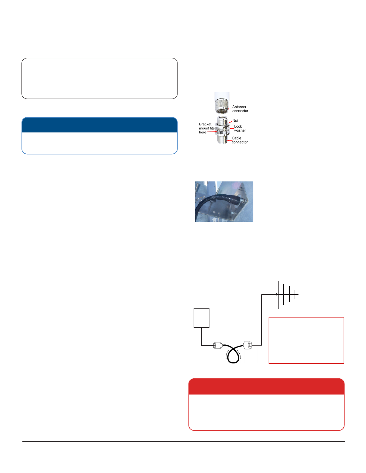
Cable Adapters
2.4 GHz 5dBi Omni and 5.8 GHz 7dBi Omni antennas
(Antenna IDs 1 and 2) require an adapter between the cable
connector and the antenna connector, in order to attach the
mounting bracket:
Adapter Type N
Female to Female
1/8" Bulkhead
The longer end of the
adapter threads into the
antenna connector.
Weatherproong
Weatherproof all outdoor connections: apply several layers
of rubber splicing or vulcanizing tape over the connection.
Drainage is very important with unpressurized radomes.
Ensure the drain hole is on the bottom, and it has not been
blocked during installation.
Drip Loops
Add a small loop to antenna and Ethernet cables to direct
rainwater ow away from the connector:
WARNING: Equipment Damage Risk
Do not remove the metal sealing caps from any
unused connectors. If the connectors are uncovered,
moisture will enter and damage the Smart-Reach AC
Base. This will void the Safe Fleet product warranty.
Water ow Water ow
Antenna
Never place a drip loop above the
access point or antennas - water can
leak down and damage the device.
Ensure the drip loop is underneath
the lowest component (either AP
or antenna) if the components are
mounted vertically apart.
Access Point
Drip Loop

© Safe Fleet | 2022 | All rights reserved Page 4
Smart-Reach AC Base Antenna Installation Guide
Antenna Types
Use the following examples to help identify supported
antennas as dened in the model number table above:
TIP: Antenna Documentation
For assembly instructions, refer to the documentation
included with the antenna product.
Number Antenna Type
32.4 GHz antenna (ideal mounting style)
Antenna Cable Connections
The model number of the Smart-Reach AC Base you
received indicates which antenna cables connect to
specic base connectors. The following are connection
steps for some common antenna and base congurations:
SRB1AC101010
1. Remove caps from antenna connector numbers
1, 3, and 5.
2. Securely attach cable connectors for the three 2.4 GHz
Omni antennas to the three connectors.
SRB1AC020202 or SRB1AC090909
1. Remove caps from antenna connector numbers
2, 4, and 6.
2. Securely attach cable connectors for the three 5GHz
Omni antennas (ID #2) or the three dual band 2.4/5GHz
mini-panel antenna (ID #9) to the three connectors.
SRB1AC606060
1. Remove caps from antenna connector numbers
1, 3, and 5.
2. Securely attach cable connectors for the three 2.4 GHz
Mini Panel antennas to the three connectors.
SRB2AC141010
1. Remove caps from antenna connector numbers
1, 2, 3, and 5.
2. Securely attach cable connectors for the three 2.4 GHz
antennas to connectors 1, 3, and 5.
3. Securely attach the cable connector for the 5 GHz grid
antenna to connector number 2.
Antenna Connectors
The image shows a top view of the access point.
Connectors labeled 1, 3, and 5 are for 2.4 GHz antennas,
while 2, 4, and 6 are 5 GHz,
45.8 GHz antenna (ideal mounting style)
9Dual band 2.4/5GHz mini-panel antenna
(ideal mounting style)
The metal plate is the back
of the mini-panel antenna;
aim the plastic housing in
the direction of the buses.

© Safe Fleet | 2022 | All rights reserved Page 5
Smart-Reach AC Base Antenna Installation Guide
Service & Support
If a Smart-Reach component is to be returned for service, please contact the Safe Fleet Technical Support team, provide
the model and/or serial# of your product, and ask for a Return Merchandise Authorization (RMA) number. An RMA# allows
the support team to better track your product when it comes in for service. Please show the RMA# on the outside of the
package.
ANY PRODUCT SENT WITHOUT AN RMA# MAY BE REFUSED!
Documentation
Additional copies of this guide along with other documentation can be found on the Safe Fleet Community
(https://community.safeeet.net).
Contact Safe Fleet Technical Support
Phone: 1.844.899.7366
Email: PTsupport@safeeet.net
Warranty
For full warranty information, visit:
• www.seon.com/documents/Seon-Warranty.pdf
This manual suits for next models
4
Table of contents
Popular Antenna manuals by other brands

DAVIS
DAVIS Windex AV 3160 installation instructions

ZCG
ZCG Y100 Series installation guide

CommScope
CommScope CMAX-OMFX-43M-I53 Installation instruction

Shakespeare Electronic
Shakespeare Electronic Style DS-3005 user manual

Antenex
Antenex VOYAGER Assembly & Tuning Information

Metronic
Metronic 415047 quick start guide

DEGEN
DEGEN BBQ 101520 Installatioin manual

Lectrosonics
Lectrosonics ALP690 instruction manual

Sea Tel
Sea Tel ST144-21 Installation and operation manual

Sea Tel
Sea Tel 9711QOR-86 Installation and operation manual

M2 Antenna Systems
M2 Antenna Systems 10M4DX Assembly manual

BAS
BAS WiFiAgent Quick user guide