Safe Living Technologies SLT-1039 User manual

Safe Living Technologies Inc. © 2019
Body Voltage Home Test Kit
For Precise “True RMS” Measurements of Body Voltage
According to International Institute of Building Biology,
Guidelines for Sleeping Areas (SBM 2015)
Measures the amount of AC Voltage coupled onto the
human body from:
- Electrical wires hidden in the ceilings, walls and floors
- Overhead power lines
- Power outlets / receptacles
- Extension cords
- Power bars
- Appliance power cables and more…

Safe Living Technologies Inc. © 2019
International Institute of Building Biology Guidelines for Sleeping Areas
Bau-Biologie (SBM 2015)
Ideal
Weak
Strong
Extreme
Body voltage in milliVolts mV
< 10
10 –100
100 –1000
> 1000
Contents of Kit:
1] Premium Body Voltage Meter including a 9V Alkaline Battery
2] Test Lead 18 inch / 46 cm - Red –For Hand Probe (4mm banana)
3] Test Lead 20 foot / 6.1 Meter - Black –For Ground Wire (4mm banana)
4] Hand Probe - 4 inch - Polished Solid Aluminum
5] Ground Plug –For Grounding to an AC Electrical Outlet
6] Outlet Tester
7] Ground Clip –Alligator Clip to assist with Grounding (4mm banana)
8] Hard Plastic Carrying Case
9] Ground Peg –7.87 inch / 20 cm
1
2
3
4
5
6
7
Understanding the Measurements
8
Page 1
Range = Auto V
0.002 Volts = 2 mV
Range = Auto V
0.057 Volts = 57 mV
Range = Auto V
0.827 Volts = 827 mV
Range = Auto V
2.318 Volts = 2318 mV
Range = Auto V
10.56 Volts = 10560 mV
9

Safe Living Technologies Inc. © 2019
Fig. 1A
Fig. 1B
Body Voltage Measurement Instruction
Assembly of Equipment
- Connect one end of the red test lead to the jack of the Body Voltage Meter labeled “ VΩHz”and the
other end to the Aluminum Hand Probe (Figure 1A, 2A)
- Connect one end of the black test lead to the jack of the Body Voltage Meter labeled
“COM” and clip the other end to the Electrical Ground (Figure 1A, 1C) or the Ground Peg via the
Alligator Clip (Figure 2A, 2B) - See below
Fig. 1C
Insert
Into
Outlet
Note: The Outlet Ground may have a small voltage on it which can cause deviations in
the actual readings. As an additional option, a Ground Rod/Peg can be used. This rod/peg
is physically inserted into moist soil outside of the home and provides a direct connection
to the earth. The best ground reference point is the one that yields the highest reading.
Caution! Test Outlet Before Inserting Ground Plug Into the AC Electrical Outlet (Fig 1B)
Outlet Ground Assembly (1)
2 Lights ON Indicates
Correct Wiring
Configuration
Page 2
Ground Peg Assembly (2)
Caution: Test Outlet to Verify Correct Wiring
Do Not Proceed Unless Outlet is Verified
Fig. 2B
Fig. 2A

Safe Living Technologies Inc. © 2019
GIGAHERT
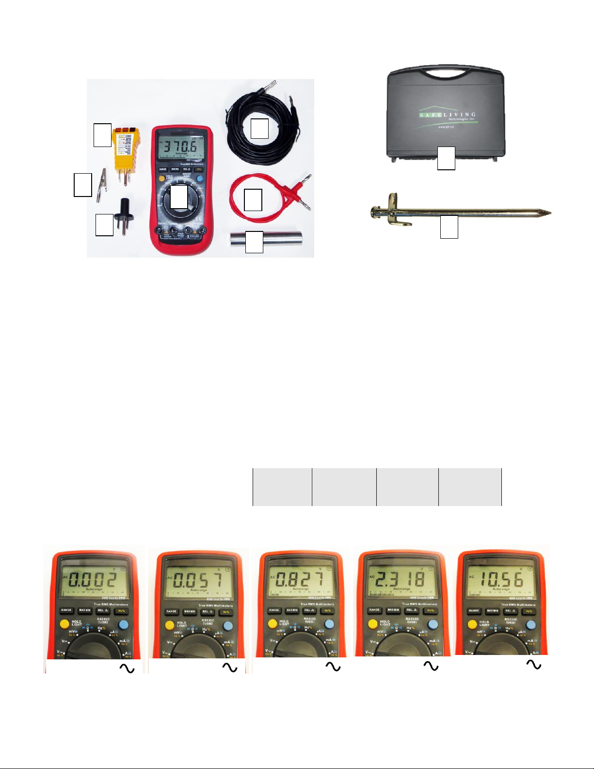
Configuring the Body Voltage Meter to Measure AC Voltage
- Rotate the “Main Selection Dial”from “OFF” to the AC Voltage Function “V”
* Note: This meter is auto ranging and will automatically select the appropriate Voltage Range.
“Autorange” will appear on the bottom of the LCD display. If a manual range is desired, press the
range button as necessary. “Autorange” will no longer appear on the LCD.
Measuring Procedure
- Ensure the equipment is assembled correctly and connected to a proper ground
- Ensure the conditions for proper measuring are met
- Ensure the Body Voltage Meter is configured correctly and the proper function and range is selected
-The person to be measured sits or lies in the position where the body voltage is to be measured
- The person should grip the hand probe snugly in one hand and remain still
- Record the body voltage measurements for future evaluation
Conditions for Proper Measuring
- Plug in all power cords from devices, appliances or extension cords that are normally connected to
outlets in the area of measurement (Including rooms beside, above and below area of investigation)
- Other people in the immediate area can influence the measurement. They should keep a minimum
distance of 5 feet
- The person to be measured should not have direct contact to the black grounding wire, the Body
Voltage Meter or any other connection to ground including an earthing pad
- The measurement is “position-sensitive” and will vary from place to place and with the position of
the measurement subject
Techniques for Reducing Body Voltage
- Begin with unplugging power cords from devices, appliances or extension cords that are normally
connected to outlets in the area of measurement, including rooms beside, above and below area of
investigation
- If there is still a significant body voltage reading then the source is from the electrical wiring in the
walls, ceiling and floors or power lines external to the building
- Temporarily shut off branch circuit breakers that supply power to the room under investigation,
including rooms beside, above and below area of investigation
Caution! If affected circuits are critical and power a refrigerator, furnace, septic pump, life
support systems, smoke or carbon monoxide detectors and so on, do not turn them off! If the
branch circuit is non-critical, one can simply turn it off via the circuit breaker or have a Remote
Cut Off Switch installed on the circuit. Please consult with a licensed electrician for proper
installation.
Safe Living Technologies Inc.
7 Clair Road West, P.O. Box 27051
Guelph, ON, N1L0A6
Canada
Tel:519-240-8735
Website: www.slt.co
For a digital copy of this manual please visit our website at:
http://www.slt.co/Products/BodyVoltageKits/HomeTestKit.aspx
Under the manuals tab.
Page 3
Table of contents
Popular Measuring Instrument manuals by other brands

Futech
Futech MULTICROSS 3D COMPACT 030.03D manual

Calypso Instruments
Calypso Instruments ULP Pro user manual

General
General DM8200 user manual

Orbit Merret
Orbit Merret OM 652UC Instructions for use

PCB Piezotronics
PCB Piezotronics IMI SENSORS M621C40 Installation and operating manual

HSS Hire
HSS Hire 49711 Operating & safety guide