Car lift installation, operation and maintenance manual Type:4SF-4000B
3
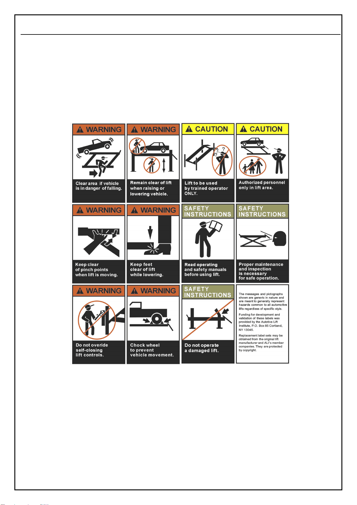
SAFETY INSTRUCTIONS
1.1 Statement
●We will give the user one-year warranty of quality for the machine. If something wrong with the machine within the term of service, we will
repair or replace the product according to the user’s demand. The manufacturer will not take any responsibility for improper installation and
operation, overload running, wrong concrete ground (that can not meet the requirements in the manual), normal mechanical abrasion and
insufficient maintenance.
●The lifting machine is designed for lifting vehicles and does not allow any other use. Neither the dealers nor we are liable for the accidents and
damage caused by the machines for other purposes..
●Be sure to pay attention to the tonnage mark on the machine and shall not attempt to lift the vehicle beyond the rated lifting weight.
●Please read the manual carefully before installation and operation of the lifting machine so as to avoid any loss of property or even personal
injury caused by improper operation.
●In the absence of the manufacturer's permission, no user may alter the control and other mechanical parts of the machine without permission.
1.2 Qualified operator and instructions for use
1.2.1 Professional trained personnel can operate the lift.
1.2.2 Electrical connections must be operated by personnel with electrical qualifications.
1.2.3 Laypeople shall not use lifting machines.
1.3 Notes
1.3.1 Do not install the lift on asphalt. The thickness of the concrete must meet the requirements.
1.3.2 Before you operate the lift, read and understand the instructions for safety operation carefully.
1.3.3 Customers do not have special needs customized, lifts are generally not used outdoors.
1.3.4 Hands and feet away from the lift’s moving parts, when the machine falling, remove the hands and feet, to avoid being hurt.
1.3.5 Professional trained personnel can operate the lift.
1.3.6 The operator is not allowed to wear fat clothing so as not to be caught in the moving parts during the lifting of the machine.
1.3.7 The lifting machine must be kept clean and tidy and should not be piled up so as not to cause accidents.
1.3.8 Work under the car, make sure the safety of the lift in occlusal state.
1.3.9 Check the parts for damage at any time, check the synchronism of the machine and the flexibility of the moving parts, and pay attention to
the regular maintenance. Once the abnormal situation is found, stop using and contact the dealer immediately.
1.3.10 Please lowest the machine after operation.
1.3.11The components of the lift shall not be altered without the manufacturer's permission.
1.3.12 If the machine is not used for a long time, the user needs
A.Cut-off power B.Emptying hydraulic fluid C.The moving parts are lubricated with hydraulic oil.