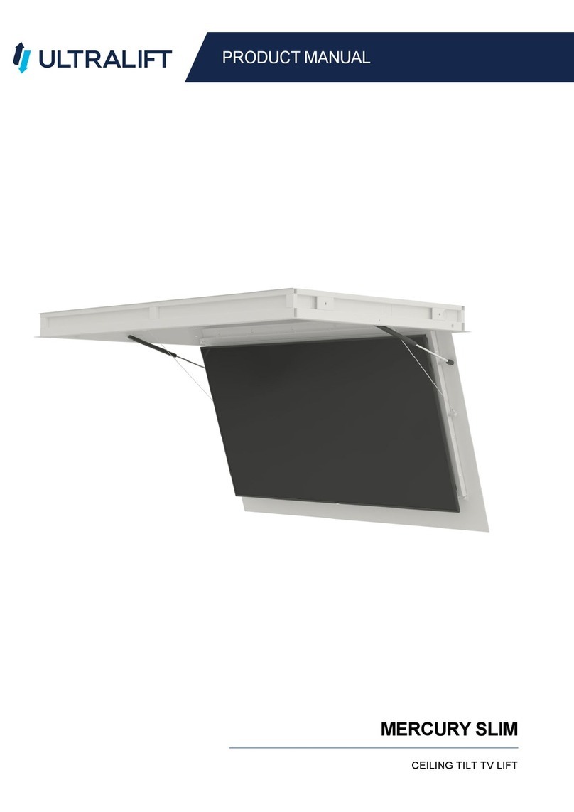
UltraLift TITAN TTN-000 User manual

PRODUCT MANUAL
TITAN DUAL LEG VERTICAL LIFT
WITH HINGED LID OPENER AND FIXED TOP OPTIONS

2
TABLE OF CONTENTS
TITAN DUAL LEG
PARTS LIST............................................................................................................................................................................. 3
PRODUCT DIAGRAM ............................................................................................................................................................. 4
INSTALLATION....................................................................................................................................................................... 7
CABLE MANAGEMENT .......................................................................................................................................................... 8
WIRING DIAGRAM ................................................................................................................................................................ 9
OPERATION: DPG1C BLUETOOTH ....................................................................................................................................... 10
OPERATION: AUTOMATION................................................................................................................................................ 12
TROUBLESHOOTING............................................................................................................................................................ 13
SPECIFICATIONS .................................................................................................................................................................. 14
WARRANTY AND RETURNS ................................................................................................................................................. 15
MOVING PARTS
Do not obstruct the operation of the mechanism with fingers or any object. Injury or damage
could result. If adjusting the limits, do so before wiring into control systems.
RISK OF ELECTROCUTION
Do not connect any power to the lift until installation is complete.
Attach the TV after the lift has been properly installed and tested.
WEAR PROTECTIVE EYEWEAR
During installation, this product, or parts of it may move in unexpected ways.
Always wear protective eyewear to ensure safety.
BE PREPARED
Organise your mounting hardware and have the necessary tools readily accessible before
installation.
NOTE
Do not expose to extreme temperatures or corrosive materials.
Minimize exposure to environmental elements such as humidity or dust. This will void your
warranty and reduce the life of the product.

3
PARTS LIST
TITAN DUAL LEG
PARTS LIST
Titan Lift with
Hinged Lid Opener
(Option 1)
Screen Hanging Rails
Wired Controller
(DPG1C Bluetooth)
Fixed Top
Panel Brackets
(Option 2)
M6, 16mm Pan Phillips screws
For fastening certain Screens to Hanging Rails QTY: 4
6.4 x 15 x 1.25 Washers
For use with M6x16 Pan Phillips screws QTY: 4
M8, 16 mm Pan Phillips screws
For fastening certain Screens to Hanging Rails
QTY: 4
9.2 x 16.8 x 1.2 Washers
For use with M8x16 Pan Phillips screws
QTY: 4

4
PRODUCT DIAGRAM
TITAN DUAL LEG
PRODUCT DIAGRAM

5
PRODUCT DIAGRAM
TITAN DUAL LEG

6
PRODUCT DIAGRAM
TITAN DUAL LEG

7
INSTALLATION
TITAN DUAL LEG
INSTALLATION
TV INSTALLATION:
Attach the Screen Hanging Rails to the back of the TV using the
correct size screws for your screen as supplied in the Bolt Kit.
Ensure Hanging Rails are properly aligned and there is no more
than 75mm between the bottom of the TV and the bottom of the
Hanging Rails. If the screen needs a slight tweak to the level, use
the Levelling Screws on the top of the Hanging Rails.
Lift the TV onto the Cross Rails, ensuring that the TV is central.
There should be a minimum of 30 mm from the bottom of the TV
to the bottom of the lift for cable clearance.
When satisfied with the positioning, lock the TV into place using the pre-installed Rails Locking Screws at the
bottom of the Hanging Rails.
HINGED LID INSTALL:
Position the Titan in its final installation position and secure through the baseplate to
the floor using at least 4 appropriate anchors (not supplied),
Hang the TV with the Hanging Rails onto the Titan Lift.
Adjust the Hinged Lid Opener so that it sits 8 mm proud of the top of the TV as the
openers push against the Hinged Lid to open it. If the TV is sitting too low, adjust the
position of the Rails on the TV. If the screen needs a slight adjustment to be level,
use the pre-installed Levelling Screws on top of the Hanging Rails.
Once the TV is in its correct position, lock it in place by tightening the pre-installed
Rails Locking Screws at the bottom of the Hanging Rails.
OPTIONAL FIXED LID INSTALL
Remove the Hinged Lid Openers to make way for the Fixed Lid Brackets.
Attach the Fixed Lid Brackets at the desired height for your Lid using the M4x12mm
screws that originally held the Hinged Lid Openers. Make sure the Lid Openers are
securely attached.
The lid can now be attached to the Lid Holders using the provided holes.
For more detailed measurements and dimensions please see Page 6.
Min 8 mm gap between the TV and lid

8
CABLE MANAGEMENT
TITAN DUAL LEG
CABLE MANAGEMENT
The Cable Management on the Titan is utilising an Energy Chain articulated cable management system. The
Energy Chain will follow the movement of the Titan lift without causing crimping or crushing of cables.
The Energy Chain has “doors” that can be opened to allow access to the cable compartment.

9
WIRING DIAGRAM
TITAN DUAL LEG
WIRING DIAGRAM
Below is an image of how the Titan is cabled (showing the DPG1C Bluetooth handheld controller), this should
not need to be changed unless swapping to an integrated automation setup using contact closure.
Ports and their uses:
•AC: 240 V, 50-60 Hz, 200 W
•A1 & A2: Parallel Controller Ports (Bluetooth, IR, or Dry Contact Closure for automation)
•1: Actuator/Column 1 Port
•2: Actuator/Column 2 Port
IMPORTANT
The lift should not be run up and down more than 4 times, or continuously at full load for
more than 1 minute without a 10-minute break.
Overheating will damage the Control Box.
240 V 50-60Hz
POWER INPUT
ACTUATOR/COLUMN 1 PORT
A1 & A2
PARALLEL PORTS
ACTUATOR/COLUMN 2 PORT

10
OPERATION: DPG1C BLUETOOTH
TITAN DUAL LEG
OPERATION: DPG1C BLUETOOTH
Follow these instructions if your product has the Bluetooth controller and handset option.
BEFORE FIRST USE:
Download the LINAK “Desk Control” app from your device’s respective App Store.
TO SET UPPER LIMIT:
•Adjust the Lift to the maximum allowable height.
•Press the Bluetooth button and tilt the controller up at the same time for 8 seconds until the LED strip
blinks and then goes solid White.
•Release the Bluetooth Button and DPG1C. The upper allowable travel limit is now set. The Lift will not
travel past this point.
TO PAIR WITH BLUETOOTH:
•Make sure Bluetooth is turned on your device
•Open the Desk Control App on your device
•On the DPG1C, press the Bluetooth button for two seconds to enable pairing mode, the LED Strip will
turn Blue.
•The Display on the DPG1C will inform the user about the Bluetooth ID of the Lift. Look for this ID in the
Desk Control App and connect to it.
TO OPERATE THE LIFT:
•Open the Desk Control app and Connect to the Lift
•Use the up and down arrows to operate the lift. The Lift will travel to the Max Upper Limit set up
previously in the setup process.
LED LIGHTING STRIP
FAVOURITE POSITIONS
BLUETOOTH
REMINDER
DPG1C Controller with Bluetooth

11
OPERATION: DPG1C BLUETOOTH
TITAN DUAL LEG
TO OPERATE THE LIFT WITH BLUETOOTH HANDSET:
•On the Desk Control App, disconnect from the matched device.
•To do this, press “More” on the App and then select the matched device.
•Select the matched device and press “DISCONNECT”.
•Your controller is now disconnected from the App.
•On the DPG1C controller, press the Bluetooth button for two seconds to enable pairing mode, the LED
Strip will turn Blue.
•Press both the “UP” and “DOWN” buttons on the HANDSET to pairs the handset with the DPG1C controller.
Please Note:
•The Desktop Control App must be used first to operate the unit at least once before following the
above procedures to use the handset.
•In the event of a power outage, you need to operate the unit with the Desktop App again at least once
before you can use the handset. Also, remember you need to disconnect the App before being able to
use the handset.
BLUETOOTH HANDSET
TO RESET THE DPG1C CONTROLLER:
•Push and hold the “Reminder” and “Favourite” buttons until the LED strip flashes Red 3 times to
indicate the resetting is done. This will remove the Upper Limit and any Favourites saved.

12
OPERATION: AUTOMATION
TITAN DUAL LEG
OPERATION: AUTOMATION
Your product can be integrated into most control systems using dry contact relays. These instructions are
provided for Automation specialist reference only. Please contact us, or an Automation specialist, before
attempting this change.
TO INTEGRATE:
Unplug and remove the original controller and replace it with a DP1U Controller. This is needed as removing
the original controller will remove any stored Up or Down limits. DP1U is used to set the Up and Down limits in
the main control unit.
SET NEW POSITIONS:
On the DP1U, press the UP arrow to bring to the desired height. Press the DOWN arrow to stop. Press the S
button and within 2 seconds press the 1 button. Memory 1 is now set.
Repeat procedure for other Memory positions.
TO AUTOMATE:
Plug in a standard CAT category LAN cable between the Control unit port A2 and external relays. Use the
pinouts below to activate the desired action. Note: a single relay pulse will cause the lift to travel in the
selected direction until it hits the full stroke length. A second pulse of the same relay will cancel the action.
CONTROL BOX PINOUT:
Function Pins Colour (T568A) Colour (T568B)
Up 4 & 5 Blue & Blue/White Blue & Blue/White
Down 4 & 8 Blue & Brown Blue & Brown
Store 2 & 8 Green & Brown Orange & Brown
Memory 1 3 & 5 Orange/White &
Blue/White
Green/White & Blue/White
Memory 2 3 & 8 Orange/White & Brown Green/White & Brown
Memory 3 2 & 5 Green & Blue/White Orange & Blue/White
DPU1 CONTROLLER STANDARS CAT LAN CABLE

13
TROUBLESHOOTING
TITAN DUAL LEG
TROUBLESHOOTING
If you are having issues with your Titan, please try the following steps:
Titan Will Not Rise:
•Check power is available and active
•Attempt to “Force Initialise” legs using Hand Controller (see below)
•Check that all appropriate cables are plugged in correctly
•If using Bluetooth, make sure the app is paired
Titan Will Not Lower:
•Check power is available and active
•Check that all appropriate cables are plugged in correctly
•Hold down on the Hand Controller
•If using Bluetooth, make sure the app is paired
Titan Will Not Raise Past Desired Position:
•Reset the travel limits using the Hand Controller
Forced Initialisation:
Forced initialisation is only needed if the two columns are not level at the same height. It is recommended to
remove the TV before attempting this procedure.
Press the “DOWN” button once (or in some cases, press and hold) until the unit is completely in the down
position. Release the “DOWN” button then press and hold again for 6 seconds. The lift should move up and
down slightly. The system is now initialised.
If you are still having issues, please contact Ultralift Australia on +61 3 9459 0873 for further support.

14
SPECIFICATIONS
TITAN DUAL LEG
SPECIFICATIONS
MODEL
TITAN
PART NUMBER
TTN-000
MIN LIFT HEIGHT (BOTTOM OF TV) (MM)
30
MAX LIFT HEIGHT (BOTTOM OF TV) (MM)
995
MIN LOAD WEIGHT (KG)
2
MAX LOAD WEIGHT (KG)
90
OPERATING VOLTAGE (V)
240
STANDBY POWER DRAW (W)
0.1
MAX POWER DRAW (W)
300
DRIVE TYPE
ACTUATOR
DRIVE QTY
2
DRIVE MODEL
DL-11
DRIVE FORCE (NM)
600
DRIVE STROKE (MM)
965
CONTROL TYPE
LINAK
CONTROL MODEL
CBD6S
CONTROL CHANNELS
2
CONSOLE MODEL
DP1-V
UNIT WEIGHT (KG)
40
SHIPPING WEIGHT (KG)
45
SHIPPING DIMENSIONS (HXWXD) (MM)
820 X 940 X 210

Copyright © Ultralift Australia, all rights reserved
82 Dougharty Road, Heidelberg West
Victoria 3081, Australia
Phone: +61 3 9459 0873
Email: sales@ultraliftaustralia.com.au
WARRANTY AND RETURNS
TITAN DUAL LEG
WARRANTY AND RETURNS
At Ultralift Australia Pty Ltd, we take pride in the fact that our products are of the highest quality. Because of
this, we offer the following programs to ensure your satisfaction.
ULTRALIFT 3 YEAR WARRANTY
1. The product is warranted for 36 months from the date of invoice. Subject to the conditions of this warranty,
Ultralift Australia or an authorised installer will perform necessary service on the product without charge
for parts or labour if, in the opinion of Ultralift Australia, the product is found to be faulty within the
warranty period.
2. This warranty only applies to Ultralift Australia products when purchased from Ultralift Australia or an
authorised dealer.
3. This warranty only applies if the product has been installed and used in accordance with the
manufacturer’s recommendations (as noted in the instruction manual) under normal use and reasonable
care (in the opinion of Ultralift Australia). The warranty covers normal domestic, commercial or
educational use only. It does not cover damage, malfunction, neglect, the build-up of dirt or dust, abuse,
maladjustment of customer controls, mains supply problems, thunderstorm activity, infestation by insects
or vermin, tampering or repair by unauthorised persons (including unauthorized alterations), exposure to
abnormally corrosive conditions or any foreign object or matter having entered the product.
4. If warranty service is required, you should:
•Contact your installer for advice on how to rectify the issue.
•If this does not solve the problem, please call Ultralift Australia on +61 3 9459 0873 for advice.
•If the device requires service, return the product to Ultralift Australia for repair.
•Please Note: Freight and insurance to and/or from the location of the device must be arranged by you.
•Please ensure that items returned are packed appropriately.
5. The warranties hereby conferred do not extend to, and exclude, any costs associated with the installation,
de-installation, or re-installation of a product. This includes costs related to the mounting, de-mounting, or
re-mounting of any screen (and any other ancillary devices), delivery, handling, freighting, transportation
or insurance of the product or any part thereof or replacement to such installation, de-installation,
reinstallation, or transit.
Table of contents
Other UltraLift Lifting System manuals
Popular Lifting System manuals by other brands

Sealey
Sealey AK98943 instructions

Telpro
Telpro Tele-Tower 1177 Operator's manual

salmson
salmson LIFTSON-S Installation and starting instructions

Peak
Peak 209C Installation and service manual

Central Hydraulics
Central Hydraulics 2792 Set up and operating instructions

IKAR
IKAR ASS-3 Log book and instructions for use