INSTALLATION & WIRING
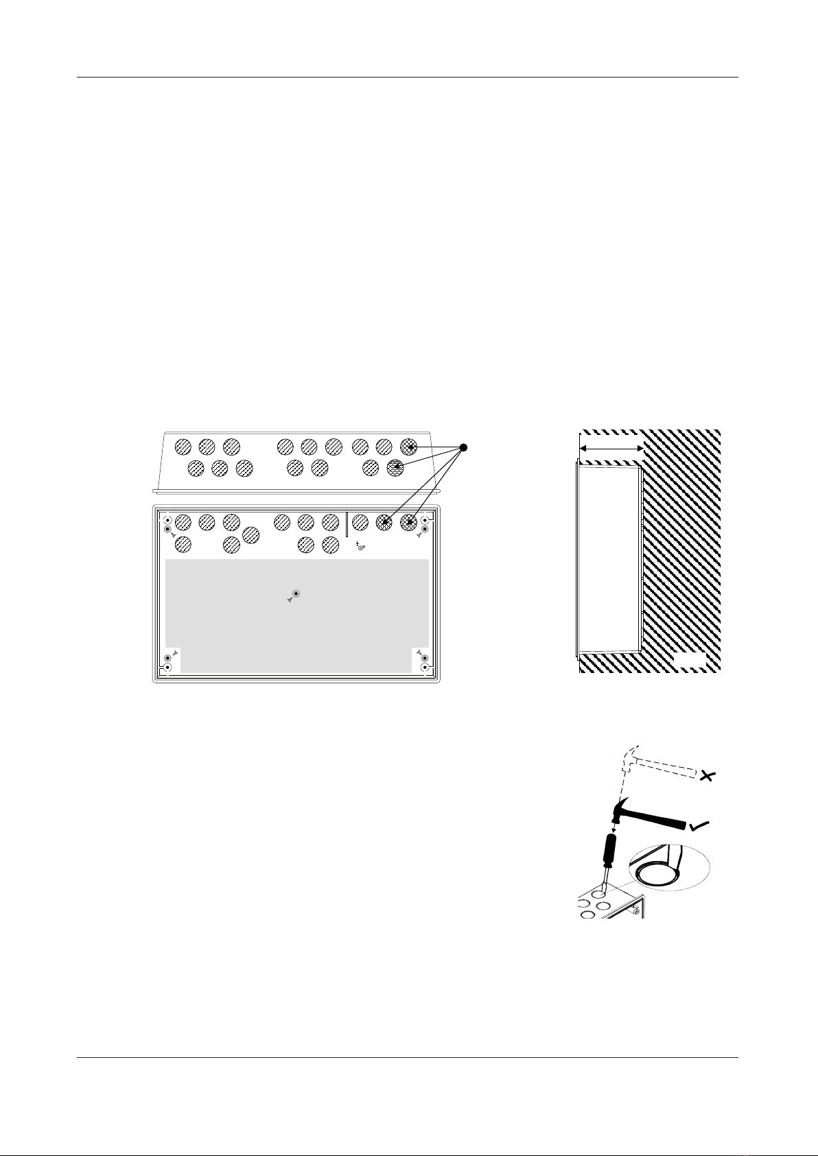
The fire panel enclosure
The panel is supplied with a plastic detachable lid, a plastic back box, a Main Control PCB, a Power
Supply PCB and a Network Communication Card. Space is available inside the panel for the rated
capacity of VRSLA backup batteries. The panel must be sited internally in an area that is not subject to
conditions that are likely to affect its performance, e.g. damp, salt-air, water ingress, extremes of tem-
perature, physical abuse, etc. It should be sited at a height where it is easily accessible and in a promi-
nent position within the building. Ideally, its front panel indicators should be at eye level.
It is recommended that you remove the panel’s lid and base PCBs prior to first fix installation to
protect the electronics from damage.
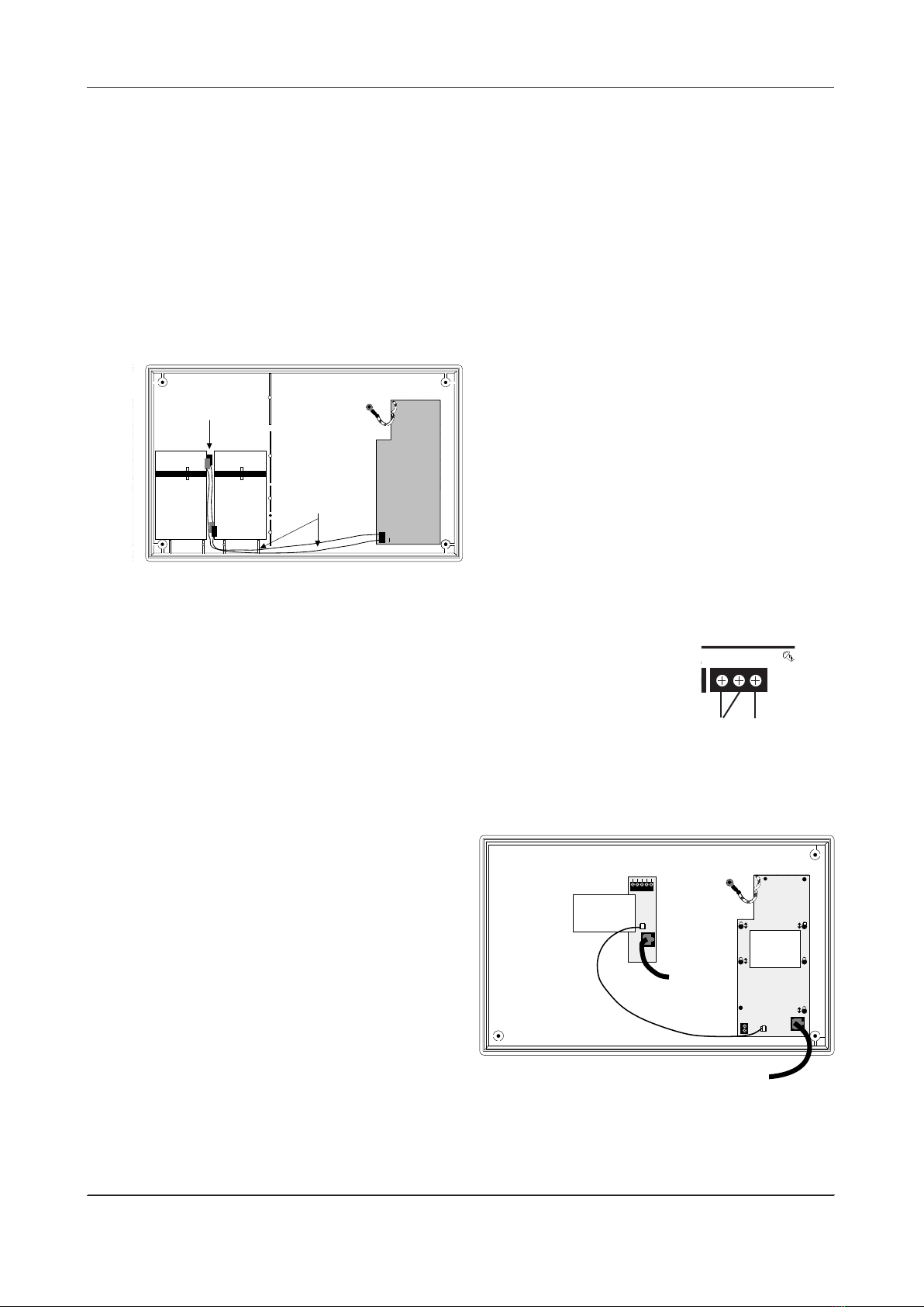
Removing the lid and base PCBs
Fig. 1 : Location of the panel’s base PCBs and removal details
1 Take the panel out of its box and undo the four lid screws using the torx key provided. Remove the lid
to expose the Main Control PCB (the Power Supply PCB and Network Communication Cardareunderneath).
2 Carefully remove the five retaining screws on the Main Control PCB and slide the PCB up and over the
mounting pillars, taking care not to damage any of the components.
3Disconnect the two telecoms-style connecting cables from PL1 on the Power Supply PCB and PL2 on the
Network Communication Card but keep them connected to the reverse of the Main Control PCB to
prevent them being misplaced.
XFP ENGINEERING MANUAL • Approved Document No. DFU1200502 Rev 1 • Page 4 of 8
XFP 16 ZONE REPEATER PANEL
Leave this end of the connector cable connected to
the socket on the reverse of the Main Control PCB
(the one above the PCB’s revision number)
BASIC OVERVIEW & KEY FEATURES
Amaximum of eight XFP Repeaters (any mix) can be connected to one non-networked XFP main panel
(note that the main panel’s Network Comms function must be set to Repeater mode).
Each Repeater requires its own dedicated mains power and battery back-up supply.
Communication between the main panel and repeaters is achieved using network communication
cards - one per repeater (fitted as standard) and one per main (available as an optional extra), wired in
1.5mm2two-core screened fire resistant cable. The total network length for a repeater network must
not exceed 500m.
Each repeater offers all the functions and controls of an XFP main panel (access levels 1, 2 and 3).
Repeaters do not include an RS232 PC programming connector. System programming must be carried
out at the XFP main panel using the panel’s upload/download programming tools and a Windows PC.
Please refer to the XFP main panel instructions for details.
Afault relay is included in all repeaters.
Leave this end of the connector cable connected to
the socket on the reverse of the Main Control PCB
(the one near the PCB’smicroprocessor)