Electrical connections
Emergency stop - kill cord#
The boat units cabling for emergency stop is connected in parallel or in series with the existing
emergency stop depending on whether it is a short-circuit or breaking-up emergency stop.
How do I know witch emergency stop my boat is equipped with?
One can easily find out witch type of emergency stop the boat is fitted with.
1. Start the engine as usual, to verify that everything works as it should.
2. Stop the engine. Locate the cables to the kill switch - emergency stop.
3. Cut off one cable. NOTE ensure that cable stub is long enough that it is possible to connect it to
the SafetyMOB boat unit.
4. Try to start the engine, if it is possible, you probably have a short-circuit emergency stop, ie
shorting the wires together will stop the engine. Try to activate your existing emergency stop, the
engine should continue to run.
If you are unable to start the engine, you probably have a breaking-up emergency stop, ie the
emergency stop breaks up the connection to the engine when activated.
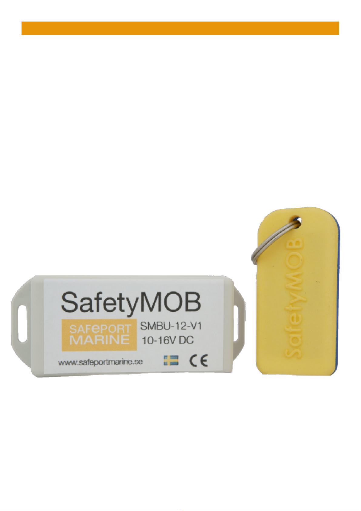
If you have a short-circuit emergency stop, connect both cables to the boat unit. Cut the second
cable to the existing emergency stop (NOTE ensure that cable stub is long enough that it is possible
to connect it to the SafetyMOB boat unit) and connect the two cables to the boat unit cables marked
NO and C (the boat unit is now connected in parallel with the existing emergency stop).
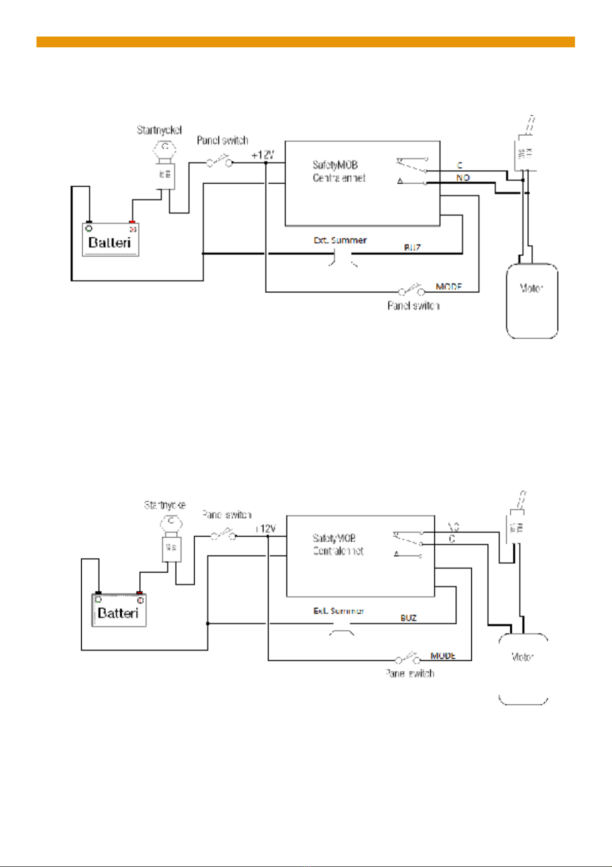
If you have a breaking-up emergency stop, connect the boat unit cable marked NC to one end of the
cut cord and C to the other end (the boat unit is now connected in series with the existing
External relay#
An external relay can be connected to the WHITE ( EXT ) wire and +12V, max load 1A /12V. This
signal ( EXT ) is grounded when the emergency stop is activated. This can be used for instance to
stop an electric motor (trolling motor). This function is latching, even if the communication is
restored the EXT signal will be activated.
Normal/low-speed mode switching
It is possible to connect a switch to the BLUE ( MODE ) wire and +12V to select between normal and
low speed mode. When the circuit is closed the system is in low speed mode, when open in normal
mode. Leave the BLUE wire unconnected if this function is not used.
External buzzer
It is possible to connect an external buzzer to the ORANGE ( BUZ ) wire and ground. Max 100mA/
12V. This buzzer will mirror the internal buzzer.