SAFETY SYSTEMS TECHNOLOGY GIR911 Guide

Model GIR911
Infrared Carbon Dioxide
NOVA-Sensor
DESIGN MANUAL
The information and technical data
disclosed by this document may be
used and disseminated only for the
purposes and to the extent
specifically authorized by SAFETY
SYSTEMS TECHNOLOGY in writing. Such
information and technical data are
proprietary to SAFETY SYSTEMS
TECHNOLOGY and may not be used or
disseminated except as provided in the
foregoing sentence.
70071
SAFETY SYSTEMS TECHNOLOGY
23282 Mill Creek Drive, Suite 215
Laguna Hills,California92653, USA
Tel(949)583-1857 Fax (909)340-6643
www.safetysys.com
The information in this document is applicable to
sensors built on or after October, 2001

Quick Finder - Model GIR911 CO2 NOVA-Sensor
QUICK START . . . . . . . . . . . . . . . . . . . . . . . . . . . . . . . . . . . . . . . . . . 911-1
Apply Power . . . . . . . . . . . . . . . . . . . . . . . . . . . . . . . . . . . . . . . . .911-1
Calibration . . . . . . . . . . . . . . . . . . . . . . . . . . . . . . . . . . . . . . . . . .911-1
Alarm Setpoints . . . . . . . . . . . . . . . . . . . . . . . . . . . . . . . . . . . . . . .911-1
DIP Switch: Latch/No Latch Setting for LOW Alarm Output . . . . . . . . . . . . . . . . .911-1
DESCRIPTION . . . . . . . . . . . . . . . . . . . . . . . . . . . . . . . . . . . . . . . . . . 911-2
Principle of Operation . . . . . . . . . . . . . . . . . . . . . . . . . . . . . . . . . . . . 911-2
TECHNICAL SPECIFICATIONS . . . . . . . . . . . . . . . . . . . . . . . . . . . . . . . . .911-3
INSTALLATION . . . . . . . . . . . . . . . . . . . . . . . . . . . . . . . . . . . . . . . . . . 911-3
The GIR911 Unit . . . . . . . . . . . . . . . . . . . . . . . . . . . . . . . . . . . . . . .911-3
Installation Sequence . . . . . . . . . . . . . . . . . . . . . . . . . . . . . . . . . . . . 911-3
Mounting the enclosure . . . . . . . . . . . . . . . . . . . . . . . . . . . . . . . . . . .911-4
Wiring . . . . . . . . . . . . . . . . . . . . . . . . . . . . . . . . . . . . . . . . . . . . 911-5
Remote Sensor Version . . . . . . . . . . . . . . . . . . . . . . . . . . . . . . . . . . .911-6
DIP Switch settings . . . . . . . . . . . . . . . . . . . . . . . . . . . . . . . . . . . . .911-7
OPERATION . . . . . . . . . . . . . . . . . . . . . . . . . . . . . . . . . . . . . . . . . . .911-8
Power-Up . . . . . . . . . . . . . . . . . . . . . . . . . . . . . . . . . . . . . . . . . . 911-8
Changing the Setpoints . . . . . . . . . . . . . . . . . . . . . . . . . . . . . . . . . . .911-8
Calibration . . . . . . . . . . . . . . . . . . . . . . . . . . . . . . . . . . . . . . . . . . 911-9
Balancing . . . . . . . . . . . . . . . . . . . . . . . . . . . . . . . . . . . . . . . . . 911-11
Recalibration Schedule . . . . . . . . . . . . . . . . . . . . . . . . . . . . . . . . . . 911-11
NOVA-SENSOR OUTPUTS . . . . . . . . . . . . . . . . . . . . . . . . . . . . . . . . . . 911-11
0 to 20 mA Current Loop . . . . . . . . . . . . . . . . . . . . . . . . . . . . . . . . . . 911-11
Relay Outputs . . . . . . . . . . . . . . . . . . . . . . . . . . . . . . . . . . . . . . . 911-11
FINAL OPERATIONAL CHECK-OUT (CompTest™) . . . . . . . . . . . . . . . . . . . . . . 911-12
How to Start the CompTest . . . . . . . . . . . . . . . . . . . . . . . . . . . . . . . . 911-13
Entering the Safety-Code™ . . . . . . . . . . . . . . . . . . . . . . . . . . . . . . . . 911-13
CompTest™Operational Sequence . . . . . . . . . . . . . . . . . . . . . . . . . . . . 911-14
MAINTENANCE . . . . . . . . . . . . . . . . . . . . . . . . . . . . . . . . . . . . . . . . 911-14
Replacing the sensor lamp . . . . . . . . . . . . . . . . . . . . . . . . . . . . . . . . 911-15
Electronics Module Replacement . . . . . . . . . . . . . . . . . . . . . . . . . . . . . 911-15
Spare Parts . . . . . . . . . . . . . . . . . . . . . . . . . . . . . . . . . . . . . . . . 911-15
TROUBLESHOOTING . . . . . . . . . . . . . . . . . . . . . . . . . . . . . . . . . . . . . 911-15
Drifting/Shifting display . . . . . . . . . . . . . . . . . . . . . . . . . . . . . . . . . . 911-15
Wiring of the CHASSIS Terminal . . . . . . . . . . . . . . . . . . . . . . . . . . . . . 911-16
i December, 2003 i

MODEL GIR911 INFRARED CARBON DIOXIDE GAS
NOVA-SENSOR
QUICK START
Apply Power
Apply +24 volts DC to the labeled terminals (+24V, 24V RET).
A 30 second countdown is displayed, followed by a brief display of the firmware revision
(e.g. “1.17”). Then the decimal points will flash while the unit displays “000” to confirm
to the user that the NOVA-Sensor readout unit is properly functioning. The readout will
next display approximately “-12" and the yellow fault LED will light. This condition
remains during the remainder of the warm-up period for the IR sensor head. If “000” is
not displayed within 5 minutes, and there isno background gas, the sensor requires initial
calibration.
Calibration
Calibration requires test gas. The concentration must be one half of the full scale rating
of the sensor (for instance, 1% test gas is required to calibrate a 2% by volume CO2
sensor). Insure that no background gas is present before initiating calibration. Press the
large MODE button on the outside of the sensor housing for at least 10 seconds. The
sensor flashes “000” while sampling the zero gas condition (10 seconds). Apply test gas
when the 000 stops flashing. “CAL” will be flashed as the gas is sampled. When finished
(approx. 40 seconds), the display will stop flashing - remove the gas now. The sensor
begins normal operation once the gas level is safely below the LOW alarm setpoint.
Alarm Setpoints
Setting
Remove housing cover to access buttons labeled “UP” and “DOWN”. Press the large
externally mounted MODE button for 1 second, orpress the UP/DOWN button. The LOW
alarm LED will light as the setpoint is displayed. Use the UP/DOWN button to alter the
value. After 5 seconds, the HIGH alarm LED and setpoint are displayed. Finally, after 5
seconds of button inactivity, the sensor will return to normal operation.
Confirming
To confirm or inspect the alarm setpoints without declassifying the area, simply press the
large external MODE button for 1 second. Each alarm setting will be displayed for 5
seconds, along with its corresponding alarm LED (LOW or HIGH).
DIP Switch: Latch/No Latch Setting for LOW Alarm Output
DIP switch position 4 (of the 4-position DIP) in the UP (Open) position selects LATCHING
mode for the LOW alarm. Placing the switch DOWN (Closed) configures the LOW alarm
as NON-LATCHING. Power must be cycled to “read” the new DIP setting.
MODEL GIR911 INFRARED CARBON DIOXIDE GAS NOVA-SENSOR
911-1 December, 2003 911-1

!The HIGH alarm is always latched due to code requirements. DIP switch
positions 1, 2 and 3 are set at the factory - DO NOT change setting! If you
suspectthatsettingshavebeenchanged,resetperinstructions onpage 911-7.
DESCRIPTION
The SST Model GIR911 Infrared Carbon Dioxide Gas NOVA-Sensor is a completely
self-contained device that measures and displays the concentration of gas accumulated
in a protected area, performs local control functions, and transmits this information to a
central control point.
Principle of Operation
The GIR911 uses the absorption of carbon dioxide at 4.25 µm for the detection of CO2.
The GIR911 contains an incandescent lamp pulsed at 4 Hz in conjunction with two
piezoelectric light sensors all contained in a plug-in housing ("optical bench"). In a
patented configuration, the sensors are close to each other and are exposed to the direct
light from the lamp, with no mirrors or other optical structures involved. In addition, almost
no light is reflected by the walls of the bench thus eliminating all possible influences from
wall contamination. The active sensor has an optical filter tuned to 4.25 µm; the reference
sensor sees the wide-band infrared signal from the lamp.
The presence of carbon dioxide will decrease the signal to the active sensorsignificantly,
while the signal to the reference sensor is almost unchanged. The electronics module
contained in the GIR911 constantly measures the signals from both sensors, averages
them to filter out noise and then calculates the ratio of the averaged active and reference
signals. With a constant length of the optical axis, the relation between the A/R ratio and
the actual gas concentration is logarithmic. The length of the optical path yields an output
for hydrocarbons that allows measurements with a resolution of 1%-2% of reading. The
ratiometric principle makes it possible to eliminate almost all effects of temperature,
aging, or fogging that would otherwise spoil the measurement. The optical operation
principle has the following advantages:
• Readings independent of Oxygen, wind, etc.
• Readings NOT influenced by cross-sensitivity and poisoning
• No burn-out, saturation, shift or drift when the detector is exposed to high gas
concentrations
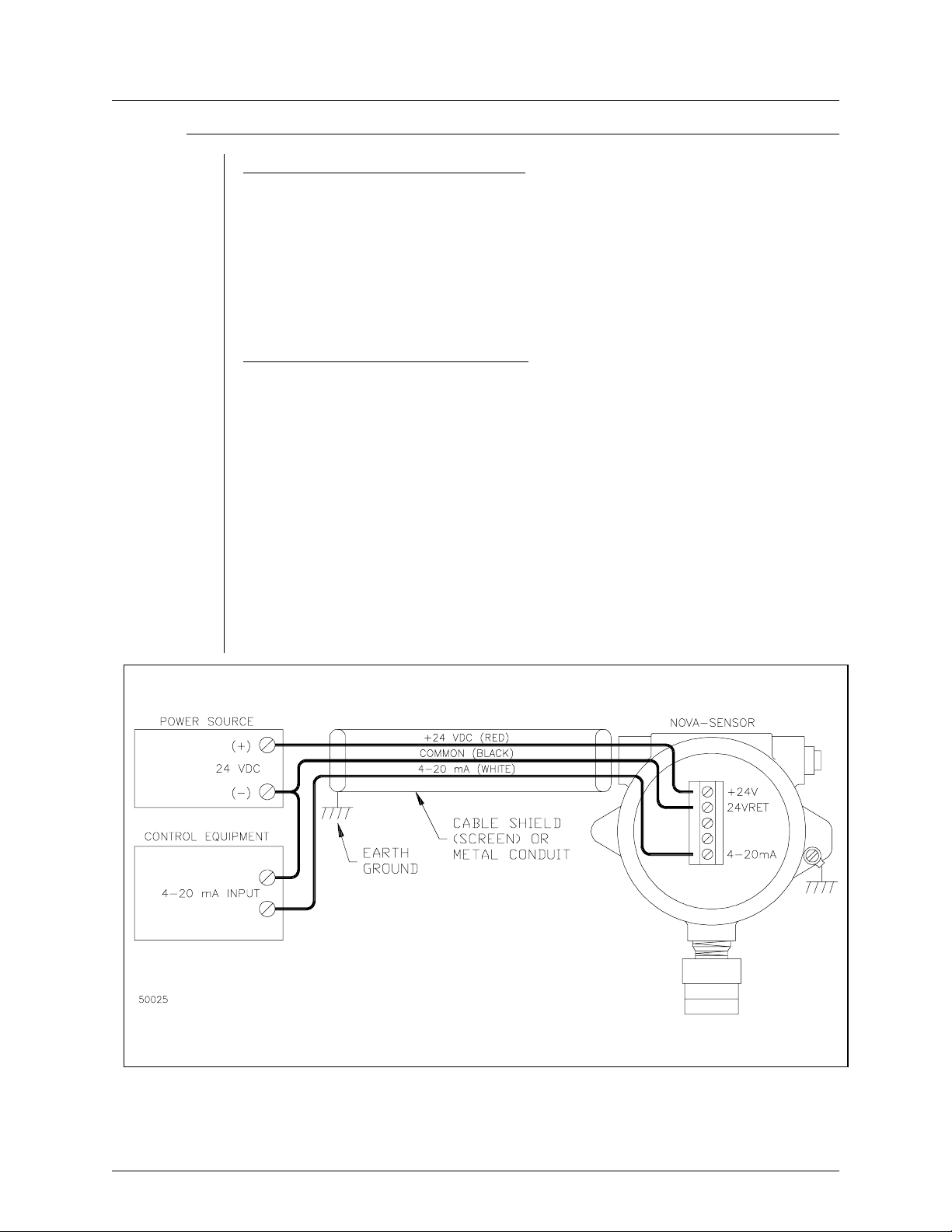
Each SST NOVA-Sensor includes a high reliability microcontroller based transmitter/con-
troller in the associated explosion proof junction box. A digital read-out is provided to
continuously display operating status and the actual concentration of gas present in
percentage by volume. The transmitter converts this reading to a standard 4-20 mA
signal. This signal may be connected to a suitable SST NOVA-5000 Gas Detection
Module, or to any other device with a standard 4-20 mA input. Connections between the
transmitter and control device are normally made with 3 conductor cable [+24 VDC, 24
V return, 4-20 mA signal]. Dry contact relay outputs are provided for the LOW alarm,
HIGH alarm, and fault. The LOW and HIGH relays operate at user adjustable alarm
setpoints; the fault relay operates upon loss of power or internal failure of the unit. Relays
are suitable for controlling local HVAC or equipment shutdown.
MODEL GIR911 INFRARED CARBON DIOXIDE GAS NOVA-SENSOR
911-2 December, 2003 911-2

TECHNICAL SPECIFICATIONS
Power Supply . . . . . . . . . . . .24 volts DC nominal, 180 mAstandby,
240 mA when in alarm. Will operate within
specifications at any supply voltage between 16
and 32 volts.
Range . . . . . . . . . . . . . . . .0 to 2% or 5% by volume Carbon Dioxide
Start-up time . . . . . . . . . . . . .15 seconds operational
20 minutes to specification
Response time . . . . . . . . . . . .5 seconds typical. Time required for measured
concentration to reach one half of the final
concentration. Measured at half scale.
Operating Temperature . . . . . . .-4 to +167oF. -20 to +75oC
Humidity . . . . . . . . . . . . . . .0-100% Relative Humidity
Resolution . . . . . . . . . . . . . .0.2% CO2
Relay Contact Ratings . . . . . . . .6 amps @ 28 VDC resistive
6 amps @ 300 VAC resistive
1/8 HP @ 120/240 VAC
Analog Output . . . . . . . . . . . .Sensor will source 0 to 20 mA DC into a load
of 600 ohms or less.
INSTALLATION
The GIR911 Unit
A complete GIR911 unit consists of an explosion-proof housing with MODE button,
Infrared gas sensor head, terminal blocks for field wiring and transparent lid used to
observe the operational status of the numerical readout and LED’s. The field wiring is
connected to the terminal blocks inside the enclosure. The terminal blocks are accessible
after removing the enclosure lid and the plug-in electronics module. The face plate on the
electronics module carries various displays and controls. These are:
• Three-digit LED readout to display of gas concentration and status.
• Four round LED’s, labeled “FAULT” (yellow), “HIGH” (red), “LOW” (red) and “CAL”
(green). These LED’s are used to signal alarms and operating modes.
• Two square pushbutton switches, labeled “UP” and “DOWN”. These switches are
accessible with a small screw driver or ball point pen and are used to adjust the
alarm trip points of the unit.
Installation Sequence
The electronics module contains parts that are delicate and potentially sensitive to
electrostatic discharge (ESD). Remove the electronics module and store in the shipping
MODEL GIR911 INFRARED CARBON DIOXIDE GAS NOVA-SENSOR
911-3 December, 2003 911-3
Table of contents