Saft 4579 Setup guide

Saft America, Inc.
711 Industrial Boulevard, Valdosta, Georgia 31601
229-247-2331 phone // 229-247-8486 fax
To: Holders of 4579 (Saft 018550-000) batteries
Revision No. 4 Dated July 13, 2001
HIGHLIGHTS
Pages which have been added or revised are outlined below together with the
highlights of the revision. Remove and insert the affected pages as listed and
ensure the Record of Revisions page has noted Revision No. 4 dtd July 13/01.
Chapter/Section
and Page Number
Description of Change
Effectivitity
List of Effective Pages
Pages 1 & 2
Revised to indicate
added, revised and/or
deleted pages
All Models
Introduction
Page Intro 1
Revised address and
updated phone numbers
All Models
Testing and Fault
Isolation
Page 111
Page 112
Added testing
parameters for shunt
connection in
Temperature Sensor
Assembly
Defined parameter for
“open” circuit in K(6).
All Models
Illustrated Parts List
Page 1002
Page 1005
Added phone numbers
and website address
Various
All Models


SAFT AMERICA INC.
711 INDUSTRIAL BOULEVARD
VALDOSTA, GEORGIA 31601
24-31-05
PAGE T-1/T-2Blank
July 13/01
COMPONENT MAINTENANCE MANUAL
WITH
ILLUSTRATED PARTS LIST
Nickel Cadmium Battery
4579
(BA06 ELDEC PART NUMBER)
(S282T002-1 BOEING PART NUMBER)
(SAFT PART NUMBER 018550-000)


SAFT AMERICA INC.
COMPONENT MAINTENANCE MANUAL
4579
24-31-05
PAGE RR-1/RR-2 Blank
July 13/01
RECORD OF REVISIONS
REV
NO. ISSUE
DATE INSERT
DATE BY REV
NO. ISSUE
DATE INSERT
DATE BY
1 02/28/84 03/01/84 Saft
2 06/15/91 07/01/91 Saft
3 01/30/98 01/30/98 Saft
4 07/13/01


SAFT AMERICA INC.
COMPONENT MAINTENANCE MANUAL
4579
24-31-05
PAGE RTR-1/RTR-2 Blank
Jan 30/98
RECORD OF TEMPORARY REVISIONS
TEMPORARY
REV NO PAGE
NUMBER ISSUE DATE BY DATE BY


SAFT AMERICA INC.
COMPONENT MAINTENANCE MANUAL
4579
24-31-05
PAGE SBL-1/SBL-2 Blank
Jan 30/98
SERVICE BULLETIN LIST
SERVICE BULLETIN
NUMBER REVISION NUMBER DATE BULLETIN
INCORPORATED INTO
MANUAL
PRODUCT IMPROVEMENTS
Product Improvements have been incorporated using service bulletins entered in the
service bulletin list. Service bulletin highlights are as follows:


SAFT AMERICA INC.
COMPONENT MAINTENANCE MANUAL
4579
24-31-05
PAGE LEP-1/LEP-2 Blank
July 13/01
LIST OF EFFECTIVE PAGES
SUBJECT PAGE DATE
Title Page
T-1
T-2
July 13/01
Blank
Record of Revisions
RR-1
RR-2
July 13/01
Blank
Record of Temporary
Revisions
RTR-1
RTR-2Jan 30/98
Blank
Service Bulletin List
SBL-1
SBL-2
Jan 30/98
Blank
List of Effective Pages
LEP-1
LEP-2
July 13/01
Blank
Table of Contents
TC-1
TC-2
Jan 30/98
Blank
Introduction
INTRO-1
INTRO-2
Jul 13/01
Blank
Description and
Operation
1
2Jan 30/98
Jan 30/98
Testing and Fault
Isolation 101
102
103
104
105
106
107
108
109
110
111
112
113
114
115
116
117
118
Jan 30/98
Jan 30/98
Jan 30/98
Jan 30/98
Jan 30/98
Jan 30/98
Jan 30/98
Jan 30/98
Jan 30/98
Jan 30/98
July 13/01
July 13/01
Jan 30/98
Jan 30/98
Jan 30/98
Jan 30/98
Jan 30/98
Jan 30/98
Disassembly 301
302
Jan 30/98
Jan 30/98
SUBJECT PAGE DATE
Cleaning 401
402
403
404
Jan 30/98
Jan 30/98
Jan 30/98
Blank
Check 501
502
503
504
Jan 30/98
Jan 30/98
Jan 30/98
Blank
Repair 601
602
Jan 30/98
Jan 30/98
Assembly 701
702
703
704
705
706
707
708
Jan 30/98
Jan 30/98
Jan 30/98
Jan 30/98
Jan 30/98
Jan 30/98
Jan 30/98
Blank
Fits and Clearances
801
802
Jan 30/98
Blank
Special Tools,
Fixtures, and
Equipment
901
902 Jan 30/98
Jan 30/98
Illustrated Parts List 1001
1002
1003
1004
1005
1006
Jan 30/98
Jan 30/98
Jan 30/98
Jan 30/98
July 13/01
Blank


SAFT AMERICA INC.
COMPONENT MAINTENANCE MANUAL
4579
24-31-05
PAGE TC-1/TC-2 Blank
Jan 30/98
TABLE OF CONTENTS
PARAGRAPH TITLE PAGE
Description and Operation 1
Testing and Fault Isolation 101
Automatic Test Requirements (ATLAS) N/A
Disassembly 301
Cleaning 401
Check 501
Repair 601
Assembly (Including Storage) 701
Fits and Clearances 801
Special Tools, Fixtures, and Equipment 901
Illustrated Parts List 1001


SAFT AMERICA INC.
COMPONENT MAINTENANCE MANUAL
4579
24-31-05
PAGE INTRO-1/INTRO-2 BLANK
Jul 13/01
INTRODUCTION
The instructions in this manual provide the information necessary for an experienced shop
technician to perform shop type repair with no specialized training.
The manual is divided into separate sections:
1. Title Page
2. Record of Revisions
3Record of Temporary Revisions
3. List of Effective Pages
4. Table of Contents
5. Introduction
6. Procedures and IPL Sections
The disassembly, repair, and assembly sections generally contain only specific instructions
to be used on the equipment covered herein. Most standard aerospace practices are not
described herein.
An explanation of the use of the Illustrated Parts List (IPL) is provided in the Introduction to
that section.
Every effort has been taken to provide complete and accurate component maintenance
instructions. However, if a situation should arise that is not adequately covered by this
manual, please contact Saft at one of the following addresses:
Saft Saft
711 Industrial Boulevard 12 Avenue Sadi Carnot
Valdosta, Georgia 31601 93170 Bagnolet, France
Telephone: (229) 247-2331 Telephone: 33 1 49 93 19 18
FAX: (229) 247-8486 FAX: 33 1 43 93 19 56
Verification:
Testing / Fault Isolation: June 15, 1991
Disassembly: June 15, 1991
Assembly: June 15, 1991


SAFT AMERICA INC.
COMPONENT MAINTENANCE MANUAL
4579
24-31-05
PAGE 1
Jan 30/98
DESCRIPTION AND OPERATION
1. Description
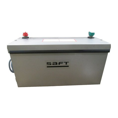
The Nickel Cadmium Battery provides power either to the standby system or to start the
auxiliary power unit (APU). It is a nickel-cadmium type with sintered plate construction, and
uses a potassium hydroxide electrolyte. The battery consists of a case and cover, 20 cell
assemblies, and a temperature sensor assembly. The sensor assembly includes a
thermoswitch mounted on a plate against the end of the center row of cells. A charge control
thermistor is located between cells 6 and 9 in the center row of cells.
2. Operation
The battery is charged on the aircraft by an on-board charger. The charge control thermistor
provides a signal to the charger to compensate the charge according to the battery
temperature. The thermostat will cut off the charger if the battery temperature exceeds a safe
operating limit.
Nickel-Cadmium Battery
Figure 1
Battery
Cover
Battery
Case
Temperature
Sensor
Assembly
Connector
Battery
Receptacle

SAFT AMERICA INC.
COMPONENT MAINTENANCE MANUAL
4579
24-31-05
PAGE 2
Jan 30/98
Voltage:
Nominal
Open Circuit Voltage, fully charged
24 Volts
26 ±1 Volts
Weight
96 lb. (43.64 Kg)
Dimensions (Maximum):
Height
Length (including side brackets)
Width (including handles)
11.4” (285 mm)
13.0” (325 mm)
11.0” (275 mm)
Cell Assembly Terminal
M10 X 1.25
Number of Cell Assemblies
20
Cell Model
VHP450KA-1
Rated Capacity
End of Life Capacity
40 Ah (1 hour rate)
40 Ah (1 hour rate)
Venting Pressure 2 to 10 psi (0.14 to 0.7 bar)
Cell Assembly Case Material Polyamide
Battery Case Material Stainless Steel
Electrolyte Potassium Hydroxide
Leading Particulars
Figure 2

SAFT AMERICA INC.
COMPONENT MAINTENANCE MANUAL
4579
24-31-05
PAGE 101
Jan 30/98
TESTING AND FAULT ISOLATION
1. General
This section contains battery functional tests and fault isolation information. Test procedures
are written in a step-by-step format following Fig 102. Fault isolation information is
presented in chart form (Fig 106).
NOTE: All ( ) part identification numbers herein are IPL, Fig 1 item numbers.
2. Required Test Equipment
NOTE:Test equipment having equivalent specifications can be used.
NOMENCLATURE APPLICATION
DC Power Supply, regulated,
35 Vdc 0-60A minimum
Testing / Fault Isolation
Precision Multi-meter,
(precision +0.5%),
0-2 V, 0-5 V, and 0-50 V scales
required
Testing / Fault Isolation
DC Load Bank (0-60A Minimum)
Testing / Fault Isolation
Thermometer, Immersion
Testing / Fault Isolation
Megohmmeter 250 Vdc Testing / Fault Isolation
Required Test Equipment
Figure 101

SAFT AMERICA INC.
COMPONENT MAINTENANCE MANUAL
4579
24-31-05
PAGE 102
Jan 30/98
NEW OR
FROM
STORAGE
CHARGE
ADJUST
ELECTROLYTE
ALL CELLS
>1.50V ANY CELL
<1.50V
INITIAL
DISCHARGE
CAPACITY TEST
GOOD NO-GOOD
REST
10 - 12 HRS.
CHARGE
ADJUST
ELECTROLYTE
SPECIAL
TESTING
*
REMOVED
FROM
AIRCRAFT
INITIAL
DISCHARGE
RESIDUAL
DISCHARGE
RECHARGE
SECOND
DISCHARGE
GOOD NOT GOOD
CHARGE
LEVEL
ELECTROLYTE
RETURN TO
SERVICE
SPECIAL
TESTING
*
ALL CELLS
>1.50V ANY CELL
<1.50V
ALL CELLS
>1.50V ANY CELL
<1.50V
*
NOTES: Record all discharge data in battery log book. *= Reentry point from SPECIAL TESTING
INSULATION
CHECK
PLACE IN
SERVICE
INSULATION
CHECK
CHECK CELL NUT
TORQUE
PG 801
CHECK CELL NUT
TORQUE
PG 801
CHECK CELL NUT
TORQUE
PG 801
CHECK CELL NUT
TORQUE
PG 801
CONTINUE
AT RESIDUAL
DISCHARGE
UNDER
“REMOVED
FROM AIRCRAFT”
Note: All procedures are found in Testing and Fault Isolation
Test Procedure Flow Diagram
Figure 102
Table of contents
Other Saft Camera Accessories manuals