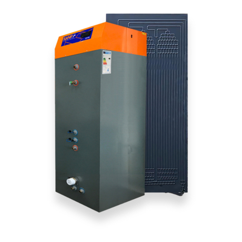
SAHP BMTB 130 User manual

V18 Mar 2019US - SD667052
HEAT PUMP WATER HEATER
BMTB 130 / 200 / 300
INSTALLATION AND
MAINTENANCE INSTRUCTIONS

2| SAHP - BMTB Installation Manual
V1 Mar 2019US - SD667052
SECTION 1 GENERAL NOTES
SECTION 2 HEALTH AND SAFETY
SECTION 3 DESCRIPTION OF THE SYSTEM
SECTION 4 PLUMBING INSTALLATION OF THE SYSTEM
SECTION 5 REFRIGERATION INSTALLATION OF THE SYSTEM
SECTION 6 ELECTRICAL INSTALLATION OF THE SYSTEM
SECTION 7 TESTING AND COMMISSIONING
SECTION 8 INSPECTION AND MAINTENANCE
SECTION 9 USING THE CONTROLLER
SECTION 10 TROUBLESHOOTING
SECTION 11 REPLACEMENT OF PARTS
SECTION 12 GUARANTEE TERMS AND CONDITIONS
SECTION 13 SERVICE RECORDS
SECTION 14 DISASSEMBLY AND RECYCLING
CONTENTS

SAHP - BMTB Installation Manual |3
V1 Mar 2019US - SD667052
SECTION 1 GENERAL NOTES
SECTION 2 HEALTH AND SAFETY
SECTION 3 DESCRIPTION OF THE SYSTEM
SECTION 4 PLUMBING INSTALLATION OF THE SYSTEM
SECTION 5 REFRIGERATION INSTALLATION OF THE SYSTEM
SECTION 6 ELECTRICAL INSTALLATION OF THE SYSTEM
SECTION 7 TESTING AND COMMISSIONING
SECTION 8 INSPECTION AND MAINTENANCE
SECTION 9 USING THE CONTROLLER
SECTION 10 TROUBLESHOOTING
SECTION 11 REPLACEMENT OF PARTS
SECTION 12 GUARANTEE TERMS AND CONDITIONS
SECTION 13 SERVICE RECORDS
SECTION 14 DISASSEMBLY AND RECYCLING
1.1 The installation of the BMTB 130 / 200 / 300 is the responsibility of
the purchaser. Read the information supplied with the equipment
carefully before installing and using it. The manufacturer declines any
responsibility as regards damages deriving from an incorrect
installation, It is the responsibility of the installer to ensure the
installation complies with all relevant local and national standards and
regulations.
1.2 Each component of the BMTB is supplied complete with its
own instruction sheet, which must be read in conjunction with
this instruction manual, and installed and maintained accordingly.
1.3 Copies of this manual and the instructions supplied with each
individual component must be handed to the client or user of the
system for their future reference and for the purpose of future
maintenance.
GENERAL NOTES
?
SECTION 1

4| SAHP - BMTB Installation Manual
V1 Mar 2019US - SD667052
HEALTH AND
SAFETY
2.1 The BMTB vented / unvented domestic hot water cylinder
range has been designed to heat domestic hot water to
130OF in vented or unvented potable water systems.
2.2 The BMTB has integral safety devices to protect the product
from internal and external faults. An adjustable digital
thermostat controls the water temperature.
2.3 The BMTB is manufactured in the United Kingdom in an
ISO9001:2000certiedfactoryandunderISO9001:2008
Quality management system.
2.4 Before installing the BMTB System please read this Installation
Manual and information individually supplied with any additional
equipment carefully and ensure all requirements are met.
2.5 The BMTB should be installed and maintained by persons
suitablyqualiedtodoso.
2.6 All systems upon completion should be subjected to the
appropriate local and national water pressure test requirements,
or, to not less than 1.5 times its maximum working pressure for
one hour. Systems containing plastic pipework should be pressure
tested in accordance with the pipe manufacturers
instructions. It is also recommended that the existing system
be pressure tested for water tightness before commencing work
in order to ascertain the condition of the system.
!
Care should be taken when moving the product. Check the weight before any lifting.
This is for the safety of the installer and customer. Ensure the product and in particular the
box are installed in a safe location and the mounting structure is adequate to withstand
the additional loads. Take care when moving equipment to ensure there is no damage to
theequipmentorexistingstructureandttings.
IMPORTANT:
This appliance can be used by children from 8 years and above and persons with
reduced physical, sensory or mental capabilities or lack of experience and
knowledge if they have been given supervision or instruction concerning use of the
appliance in a safe way and understand the hazards involved. Children should not
play with the appliance. Cleaning and user maintenance shall not be made by
children without supervision.
SECTION 2

SAHP - BMTB Installation Manual |5
V1 Mar 2019US - SD667052
HEALTH AND
SAFETY
2.7 Magic Box International Cylinders must be stored in the supplied
packaging in an upright orientation and should be stored in a dry
environment. The equipment should always remain in an upright
position during transport and installation. If turned on its side,
return the box to the upright position, check the compressor for signs
of leakage and leave to rest for 12 hours, before turning the unit on.
Magic Box International declines any responsibility as regards
damages deriving from incorrect transportation.
2.8 If transporting in the horizontal orientation, ensure the unit is laid down
on it’s left hand side, so that the left hand side is facing the ground.
Failure to do so may cause permanent damage. Magic Box
International declines any responsibility as regards damages deriving
from incorrect transportation.
2.9 Care should be taken when moving the product. Check the weight
before any lifting. This is for the safety of the installer and customer.
Ensure the product is installed in a safe location and the mounting
structure is adequate to withstand the additional load. Take care when
moving the equipment to ensure there is no damage to the
equipmentorexistingstructureandttings.
2.10 Safe manual handling and lifting procedures must be used when
carrying products.
!
SECTION 2

6| SAHP - BMTB Installation Manual
V1 Mar 2019US - SD667052
!
DESCRIPTION
OF THE SYSTEM
3.1 The BMTB heat pump water heater (BMTB) consists of a Solar Assisted
heat pump, coupled with either a 32, 54 or 79 gallon capacity hot
water storage tank. The Solar Assisted Heat Pump is integral to and
positioned on top of the unit within the unit casing.
3.2 The BMTB is designed to heat the domestic hot water within the
tank up to 130OF.Themaximumtemperatureisinuencedbythe
individual installation, pipe lengths and insulation. It uses an exterior
aluminium panel (evaporator) to absorb energy from the ambient air.
A copper coil(condenser) is wrapped around the external wall of the
inner cylinder which heats the water inside the cylinder. The product
hasareciprocatingcompressorforquietandefcientperformance.
With these features the BMTB is designed to have a long, trouble free
life.
3.3 The BMTB has integral safety devices to protect the product from
internal and external faults. An adjustable digital thermostat, locted at
the front of the BMTB controls the water temperature.
3.4 The BMTB is designed to store potable water supplied from the public
mains with a maximum of 200 p/m.
3.5 The BMTB has a built in timer which once a week heats the water in
the cylinder above 140OF to provide pasteurisation.
3.6 The BMTB is manufactured in the United Kingdom in an
ISO9001:2000certiedfactoryandtestedtoEN16147,UL1995,CE,
CSA.
3.7 SAHP supplies an Installation Kit which contains items that will be
needed on the installation of the BMTB’s refrigeration circuit.
SECTION 3

SAHP - BMTB Installation Manual |7
V1 Mar 2019US - SD667052
!
SECTION 3
DESCRIPTION
OF THE SYSTEM continued
Specications
Maximum cylinder volume (US gal)
Mean thermal capacity (BTU/hr)
power consumption (W)
Operating current (a)
Voltage (v) / frequency (Hz)
Operating temperature range (ºF)
Refrigerant uid and charge (Ibs)
Max. Hot water temperature (ºF)
BMTB weight unlled/lled (lbs)
Dimensions (height x width x depth(“)
Clearances Top/front (“)
Max water circuit working pressure (psi)
Cold water input connections (“)
Hot water output connections (“)
Single panel weight (Ibs)
Single panel dimensions (h x w x d ”)
Double panel weight (Ibs)
Double panel dimensions (h x w x d ”)
Thermodynamic panel input / output
Lubricant in the compressor
Sound Power Level
R134a Global Warming potential
3.8
BMTB 300
79
2580-6800
Typically 600
4-5
220 - 240, 50/60
32-105
R134a / 2.64
130
322/983
84.6 x 25.6 x 25.6
4/15
45
3/4
3/4
17.64
66.9 x 31.5 x 1
33.06
66.9 x 31.5 x 4
3/8 / 3/8
ESTER / IOSS
41Db(A)
(GWP) 1430
BMTB 130
34
2580-6800
Typically 600
4-5
220-240, 50/60
32-105
R134a / 2.64
130
183/470
50.8 x 21.7 x 21.7
4/15
45
3/4
3/4
17.64
66.9 x 31.5 x 1
33.06
66.9 x 31.5 x 4
3/8 / 3/8
ESTER / IOSS
41Db(A)
(GWP) 1430
BMTB 200
52
2580-6800
Typically 600
4-5
220-240, 50/60
32-105
R134a / 2.64
130
234/675
66.1 x 23.6 x 23.6
4/15
45
3/4
3/4
17.64
66.9 x 31.5 x 1
33.06
66.9 x 31.5 x 4
3/8 / 3/8
ESTER / IOSS
41Db(A)
(GWP) 1430

8| SAHP - BMTB Installation Manual
V1 Mar 2019US - SD667052
4.1 The BMTB must be installed on a stable base which must be capable
of supporting the weight when the cylinder is full of water.
4.2 Access for maintenance of all equipment should be considered when
positioning the vented / unvented cylinder. Care should be taken
that the immersion heater can be withdrawn for servicing if required
these are 15” long. Relevant local and national standards should
always be followed when installing discharge pipe work from the
safety valves.
4.3 We recommend that the hot and cold water requirements of the
property and user are ascertained before the installation of the BMTB
either unvented type or vented type.
4.4 The minimum incoming cold water mains inlet requirements for the
BMTBis20psioperatingpressureand5USgalperminuteowrate.
4.5 Adjustable pressure reducing valve factory set at 43.5 psi is supplied
withtheBMTBwhichmustbettedintheincomingcoldwatersupply
to the cylinder. The pressure reducing valve will deliver maximum of
13 US gal per minute.
4.6 Inhardwaterareaswerecommendthatawatertreatmentunitistted
to eliminate the formation of limescale in the system.
4.7 Do not install the equipment in the following places as they will lead
to a malfunction of the equipment: areas with corrosive gases,
factorieswheretheelectricalvoltageexperienceswideuctuations,
placeswithstrongelectromagneticwaves,placeswithinammable
materials or gases, other special environments.
PLUMBING
INSTALLATION
!
SECTION 4

SAHP - BMTB Installation Manual |9
V1 Mar 2019US - SD667052
SECTION 4
PLUMBING
INSTALLATION continued
!
4.8
A
B
C
D
E
F
G
H
I J
K
L
M
N
O P Q R
S
A
B
C
D
E
F
G
H
I
J
K
L
M
N
O
P
Q
R
S
Thermodynamic evaporator panel
Big Magic Thermodynamic Box
Hot water outlet
Pressure & temperature relief valve
Dual thermostat
Sensor pocket
Boiler ow
Immersion heater
Boiler return
Cold water in
Drain
Tundish
Pressure relief valve
Expansion tank
One way valve
Pressure reducing valve
Isolating valve
Cold main
Isolating valve
Fig

10| SAHP - BMTB Installation Manual
V1 Mar 2019US - SD667052
PLUMBING
INSTALLATION continued
!
4.9 Afullborecoldwaterisolatingvalvemustbettedinthecoldwater
supplytotheBMTB.Thisvalveisnotsuppliedwiththettingkitofthe
unit.
4.10 It is good practice to position the mains inlet control manifold at the
top of the unvented unit to ensure that the cylinder does not have to
be drained down for the purpose of maintenance.
4.11 The expansion vessel can be mounted in any Orientation. Access
must be available to the top and bottom of the vessel. The vessel
shouldbexedtoasolidwallusingthebracketsprovided.Please
remember that the vessel will get much heavier once it is full of water.
4.12 For mixer showers and taps a balanced cold feed at the same pressure
as the hot feed may be necessary. A 3/4” balanced connection on
the inlet manifold is provided for this purpose. Pipe work should
initially run in3/4” then this can be reduced where necessary.
4.13 We highly recommend installing a thermostatic mixing valve in system
where the set point temperature of either the heat pump or any heat
sources connected to the boiler coil are set to 120OF or above.
4.14 All exposed pipe work should be insulated and additional
considerations should be taken to protect the unit from frost damage.
Particular care is needed if the cylinder is to be installed in an exposed
location such as an out building or garage.
4.15 Beforellingandpressuringthecylindercareshouldbetakento
checkandtightenallconnectionsincludingfactoryttedconnections
as they may work loose during transportation and positioning.
All of the pipe work connections on the cylinder are either 3/4”
compression or 3/4” copper tube should only be used to
connect to these connections. Good working practices should be
used when preparing pipe work such as using correct pipe cutters
and de-burring.
4.16 The boiler coil connections supplied are compression connections.
The boiler circuit must be positively pumped, gravity circulation will
not provide the required heat transfer through the coil.
SECTION 4

SAHP - BMTB Installation Manual |11
V1 Mar 2019US - SD667052
SECTION 4
PLUMBING
INSTALLATION continued
!
4.17 The boiler coil has a maximum working pressure of 50psi.
With pressurised boiler circuits an additional expansion vessel
needs to be sized to suite the circuit volume and installed along
withasafetyreliefvalveandllingloop.
4.18 The boiler coil connection must be complete with thermostatic
temperature controls. Uncontrollable heat sources such as wood
burning store are not suitable. A two port motorised zone valve should
beinstalledintotheprimaryowbeforethecylinder.
4.19 ThedischargepipeworkoftheBMTBunventedunitmustbettedto
comply with the latest version of relevant local and national standards.
4.20 Beforellingpleaseensurethepressureintheexpansionvesselis
43.5psi. This is the same as the setting of the pressure reducing
valve. The valve is a Schrader type. If the pressure reducing valve setting
is amended, the expansion tank pressure must be amended to match
the same settings
4.21 Uponcompletionthewholeinstallationmustbethoroughlyushedto
removeallinstallationdirt,uxesandmanufacturingoilsbefore
beingputintooperation.Toushthesystemrstllthesystem.
Close the cold water supply full bore isolating valve. Completly drain the
tank (outlets may need to be opened during this process.) Open the
coldwatersupplyfullboreisolatingvalve.Rellthetankwithwaterand
repeat.

12| SAHP - BMTB Installation Manual
V1 Mar 2019US - SD667052
5.1 Aluminum Panel (evaporator) Connections
TheThermodynamicaluminumpanelevaporatorhasa3/8”male
areconnectionLiquidinletand3/8”maleareconnectiongas
outlet that allows connection of the the panel to the BMTB.
Connecting3/8”copperrefrigerationpipeworkmustbeared
andsecuredusing3/8”arenuts.Tohelpeliminateleaks,use
refrigerationoilonthethreadofthe3/8”areconnectionsbefore
tighteningthearenut,no soldering or brazing is permitted.
The heat pump liquid line must be correctly connected to the panel
liquid inlet. Incorrect orientation will resort in compressor failure
The Liquid inlet can be identied by the three inated
tubes extending from the connection. Please see gure 2
5.2 Thermodynamic Panel Location
The thermodynamic panel can be located facing any aspect.
On either an exterior wall or pitched roof. If the panel is installed
onaroofitshouldbexedusingappropriatesolarroofmounting
kits in accordance with relevant local and national standards.
5.3 The thermodynamic panel can be installed in a vertical
(portrait) position or horizontal (landscape) orientation but there
must be a minimum of a 30Otilt.thepanelcannotbelaidat,
also ensure the gas outlet is always orientated to the lowest
pointoftheasperthegure3.Incorrectinstallationwillinhibit
thefreeowoflubricatingoil
NOTE: Vertical panel orientation offers optimum performance
allowing even ow of refrigerant across the panel.
NOTE: For increased performance, install the panel parallel
to the prevailing wind allowing the air to pass freely over
the surface of the panel.
REFRIGERATION
INSTALLATION
!
Liquid
(inlet)
Gas (outlet)
Fig 2
SECTION 5

SAHP - BMTB Installation Manual |13
V1 Mar 2019US - SD667052
SECTION 5
5.4 Thermodynamic Panel Fixing
ToxthepaneltoanexteriorwallusethesuppliedL-brackets,
nuts,bolts,xingscrewsandplugswhichareallsuppliedinthe
installers pack.
5.5 FixtheLbracketstothethermodynamicpanelasshownin
Figure4.EnsuretheBoltsarexedwiththeboltheadfacingout.
5.6 Fix and secure the thermodynamic panel to a wall as show in
gure4.Ensuretoxall6Bracketstothepanelandexteriorwall.
NOTE: Ensure that the BMTB IS connected to the thermodynamic
panel correctly as shown in gure 5 failure to do so can result in
compressor failure and will invalidate any guarantee.
NOTE: Do not paint over the panel. This will decrease efciency and
potentially cause system failure.
!
GAS
OUTLET
ALWAYS
DOWN
GAS
OUTLET
NEVER
UP
Fig 3
REFRIGERATION
INSTALLATION continued

14| SAHP - BMTB Installation Manual
V1 Mar 2019US - SD667052
5.7 Refrigeration Connections
TheBMTBhasa3/8”maleareconnectionLiquidoutletand
3/8”maleareconnectionsuctionline(asseeningure5),
that connect the BMTB to the thermodynamic panel.
Connecting3/8”copperrefrigerationpipeworkmustbeared
andsecuredusing3/8”arenuts.Theheatpumpliquidmust
be connected to the corresponding aluminum panel liquid line.
IncorrectorientationWILLresultincompressorfailure.Tohelp
eliminate leaks, use refrigeration oil on the thread of the
3/8”areconnectionsbeforetighteningthearenut.
5.8 Pipework Installation
All refrigeration pipework should be installed in accordance
with ISO 5149.
5.9 The BMTB is factory pre-charged with refrigerant R134a with
enoughrefrigerantforupto26footofpipelengtheachway
between the BMTB and the thermodynamic Panel.
!
Bolt
Double Panel
Single panel L bracket
Nut
Wall
50 mm Spacing
Fig 4
Double panel L bracket
Single Panel
50 mm Spacing
Wall
BoltNut
BoltNut
REFRIGERATION
INSTALLATION continued
SECTION 5
Fig 5
FRONT VIEW
Liquid line (left hand side)
Suction (gas) line (right hand side)

SAHP - BMTB Installation Manual |15
V1 Mar 2019US - SD667052
5.10 The pipe length can be extended up to 50 foot each way.
However for every extra 3 ft of physical separation between
theBMTBandpanel1.6ozsofrefrigerantgasmustbe
added. The minimum pipe length between the thermodynamic
panel and the BMTB is 10 ft.
5.11 A double panel can be installed instead of a single panel.
If a double panel is used an additional 0.22 Ibs of refrigerant
gas is required, this is in addition to any gas added as per 5.10.
5.12 The refrigeration circuit shall be designed with as few bends as
possible, with a maximimum 90Obend radiance to minimize
the load loss and it shall be supported properly with a view not
to transmit stresses or vibrations
!
Fig 5
Suction line (Gas)
Liquid line (Liquid)
Suction line (Gas)
BACK VIEW
BACK VIEW
Ensure that the BMTB IS
connected to the
thermodynamic panel
correctly as shown here,
failure to do so can result
in compressor failure
REFRIGERATION
INSTALLATION continued
SECTION 5

16| SAHP - BMTB Installation Manual
V1 Mar 2019US - SD667052
5.13 Ensure that refrigeration quality copper pipes only are used
to connect the Thermodynamic Panel to the BMTB. It must
also be ensured all refrigeration pipework is insulated
withexibleanti-condensationinsulation.
NOTE: Direct contact between the refrigeration outlet and
refrigeration inlet line shall be avoided to prevent energy losses in
the system.
NOTE: Ensure the BMTB liquid outlet is connected to the
Thermodynamic Panel liquid inlet, and the BMTB suction side is
connected to the Thermodynamic Panel gas outlet.
NOTE: Do not loosen or open service ports until all connections are
made and the system has been fully leak checked and vacuumed.
NOTE: Do not Cover the brass plate nuts with the anti-vibration
insulation as this may create a freeze / thaw action on the brass which
may result in the are nut braking down over time.
5.14 Nitrogen Pressure Test
First pressure test the refrigeration circuit with Oxygen Free
Nitrogen.Nitrogencanbeintroducedusingtheserviceport
connectionasshowningure5.
!
BMTB
Fig 6
Thermodynamic unit
Refrigeration
circuit
REFRIGERATION
INSTALLATION continued
SECTION 5

SAHP - BMTB Installation Manual |17
V1 Mar 2019US - SD667052
5.15 Fill the system to 115psi, hold and monitor for 45 minutes.
Check all the refrigeration connections with a leak detector.
If during the 45 minutes of monitoring the pressure in the
systemdeclines,tightenorre-aretheconnectionandrestart
the test. Repeat if necessary until pressure is maintained for the
45 minutes.
NOTE: Ensure through the process that the pressure does not
exceed 145psi in the Thermodynamic Panel and/or the pipe work
5.16 Vacuum
Once the pressure test has been successfully completed and
noleakageofnitrogenhasbeenconrmed,thenitrogencan
be vented. The vacuum pump must be connected into the
service port to begin vacuuming / evacuating the system.
Vaccum the system to 0.5 torr (500 microns) and below for a
minimum of 45 minutes.
5.17 Releasing Refrigerant
Once the System has been successfully pressure tested and
vacuumed,nextreleasethefactorypre-charged2.64Ibsof
R134a refrigerant gas.
5.18 To do this use a 4mm allen key and rotate both service port
valves counter clockwise until fully open.
NOTE: Open the liquid line service port rst and then the gas line
service port
!
Thermostatic expansion
Valve (TEV)
Compressor
Capacitor
H/P safety switch
(auto reset)
Service Ports (3/8”)
Fig 7
FRONT
BACK
REFRIGERATION
INSTALLATION continued
SECTION 5

18| SAHP - BMTB Installation Manual
V1 Mar 2019US - SD667052
6.1 The BMTB shall be electrically connected once all the refrigerant
connections and plumbing connections are completed. All electrical
workistobecarriedoutinaccordancewiththeNECstandards,
latest issue or local codes of practice as applicable. Ensure to also
installtheequipmentinlinewithEMC2004/108/EC.
6.2 The power supply of the BMTB is single phase: 220V - 240V / 50Hz
-60Hzwithgroundconnection.Thissupplyneedstobeseparately
isolated and protected by an appropriately sized fuse (13Amps)
6.3 All electrical work is to be carried out in accordance with the latest
issue local codes of practice as applicable. Ensure to also install the
equipment in line with relevant local and national standards.
NOTE: In Area’s with 110V branch circuits within the home, you will be
required to install a dedicated single phase 220 - 240V circuit from the
electrical consumer panel to provide 220 - 240V power supply to the
BMTB. Be sure to clearly label the wires 220 - 240V on each end for safety.
NOTE: In areas with 4 conductor L1, L2, N and G wiring, connect L1 to L,
L2 to N and G to ground.
6.4 The power supply of the integral Immersion Heaters is single phase:
220V–240V/50Hz–60Hzwithgroundconnection.Onlyusethe
manufacturers supplied immersion heater. Immersion heaters should
not have a higher capacity than 5000btu/1.5kW if directly connected to
the Heat Pump. If Immersion Heaters with a capacity higher than
1.5kW/5000btuarespecied,theymustbeindependentlywiredtoa
separate fused switch. Also available are 3kW/10000btu and
6kW/20000btuimmersionheaters.contactyourdistributer.
ELECTRICAL
INSTALLATION
!
SECTION 6
Electrical
connections
Fig 8

SAHP - BMTB Installation Manual |19
V1 Mar 2019US - SD667052
!
Fig 9
ELECTRICAL
INSTALLATION continued
SECTION 6
DIMS
ALL SHARP EDGES AND BURRS TO BE REMOVED
TOLERANCE UNLESS SPECIFIED
TITLE
DIMS
3rd ANGLE PROJECTION
TOLERANCE UNLESS SPECIFIED
TITLE
mm
DO NOT SCALE PRINT
HOLES TO BS 4500 E12
1:2
SCALE
COM
SENSOR
NL
OUT 2
OUT1
N/O
N/C
N/O
4
COM
COMPRESSOR
N L
BR 1.0
B 1.0
MAINS
CABLE
BR 1.0
B 1.0
COVER EARTH
G/Y 1.0
COMP
G/Y 1.0
NTS
WIRING DIAGRAM
MAGIC BOX UL
ADD LINK R 1.0
NOTES
0.5 = 0.5mm² CONDUCTOR SIZE
1.0 = 1.0mm² CONDUCTOR SIZE ETC
CIRCUIT
B
BR
SWITCH
B 1.0
FRONT
TERMINALS
REAR
TERMINALS
KLIXON CAPACITOR
BR 1.0
R1.0
G/Y 1.5
SWITCH
HEATER
TERMINALS
CAPACITOR
G/Y 1.5
BR 1.5
B 1.5
IMMERSION
HEATER
L
N
E
MAINS
CABLE
IMMERSION
HEATER
E
L
N
HP
SWITCH
SENSOR
BASE EARTH
Prb 1
2
B 1.0
B 1.0
BR 1.0
G/Y 1.0
DIGITAL STAT
5
8
R 1.0
HP SWITCH
GR 0.5
2
1
3
DIGITAL THERMOSTAT
1 2 3 4 5 6 7 8 9 10 11 12 13 14
15 16 17 18 19 20 21 22 23 24 25 26 27 28
V 0.5
O 0.5
R 0.5
G/Y 1.0
BR 1.0
P1.0
P1.0
W1.0
W1.0
G/Y 1.0
27
1817
28
21
19
20
L
N
B Blue
Br Brown
G/YGreen/Yellow
R Red
Gr Grey
O Orange
V Violet
P Pink
W White
SUPPLY
CN/O
OUT 4
CN/O
OUT 2
CN/O CN/C N/O
OUT 3OUT 1
B 1.0
B 1.0
BR 1.0
GR 0.5
Wiring
diagram
6.5 Each immersion comes complete with integral control thermostat
and a high limit cut-out.

20| SAHP - BMTB Installation Manual
V1 Mar 2019US - SD667052
ELECTRICAL
INSTALLATION continued
SECTION 6
!
PV
connectivity
6.6 Toreplacetheimmersionrstdissconnectthepowersupplyand
drain the tank. disconnect the immersion wiring before unscrewing
the immersion heater. Screw in the new immersion heater - reconnect
thewiring,rellthetankandreconnecttheelectricalsupply.
6.7 Correct wire sizing must be carried out based on the power, wire
length and wire enclosures however in most domestic applications
14gaugewireissuitable.Heatresistancesheathedexcomplying
to relevant local and national standards should be used.
6.8 Do not energize the immersion heater until the cylinder has been
ushedandlledwithwaterasthiswillcausedamagetotheelement.
6.9 Do not operate the immersion heater if any cleaning agents are in the
cylinder as this will also cause premature failure of the immersion element.
6.10 The BMTB Thermodynamic Heat Pump ‘Blueberry’ controller has
the functionality to connect to a Solar PV PV inverter system. If you are
not connecting the BMTB to a PV Inverter proceed to section 7.
6.11 To connect the BMTB to a PV inverter a 2 conductor wire is required.
There is no maximum or minimum distance requirements of this 2
conductor wire. The cable will be carrying a voltage free signal.
6.12 Connectthe2corecabletotheunoccupiedterminals5and8
as per the wiring diagram, located on the BMTB Blueberry
controller sensor terminal located on the top right hand side of
the back of the controller. Connect the other end of the two core
cabletoaN/OrelayofthePVinverter.
6.13 IncaseswhereaN/Orelayisnotavailablewithintheinverter,
the controller can be connected via a 2 conductor voltage free
wire to an independent 7 days timer instead which allows the
controllertobeautomaticallyactuatedatapredenedrangeof
hours which can correspond to the assumed maximum PV energy
generation.
6.14 WhenthePVinvertergenerateselectricity,theN/Orelaywill
close, which will subsequently signal the Blueberry controller to
enter Eco Mode, a programme in which BMTB will automatically
raise the set point temperature input of the controller of the water
within the connected cylinder to 140°F and re initiate heating
again once the water temperature falls below 135°F.
This manual suits for next models
2
Table of contents
Other SAHP Water Heater manuals
Popular Water Heater manuals by other brands

Techtanium
Techtanium MP 50 Installation and operation instructions

Navien
Navien NR Series Service manual

Rinnai
Rinnai RSC160i Installation and operation manual

Rinnai
Rinnai Circ-Logic RU98i installation manual

Lochinvar
Lochinvar COPPER-FIN CW 645 Designer's guide

Kenmore
Kenmore 33124 - Power Miser 12 owner's manual

Eco-King
Eco-King Saga - S Series installation manual

Shuang Ri
Shuang Ri SR501 Operation manual

thermo mate
thermo mate ES150B manual

AER
AER AM-R Series Installation and maintenance instructions

RED-RING
RED-RING AV3S Installation and user guide

Eco-Smart
Eco-Smart POU 4T Installation instructions & owner's manual